

Page 1
COMFORTSTEAM
H U M I D I F I C A T I O N S Y S T E M
TM
COMFORTSTEAM
H U M I D I F I C A T I O N S Y S T E M
TM
!
TM
COMFORTSTEAM
H U M I D I F I C A T I O N S Y S T E M
Aug. 2009
Page 2

COMFORTSTEAM TM ELECTRONIC HUMIDISTAT
Features
• State of Art digital RH sensor
• ROOM or DUCT mounting
• Reprogrammable Microcontroller
• Potentiometer Set-point setting
• Out-door temperature sensor for Set-point Reset
• Green (ON/OFF) and Red (warning) status LEDs
Specications
Set-point range. . . . . . . . . . . . . . . 20% to 50% Relative Humidity
Accuracy. . . . . . . . . . . . . . . . . . . . ±4.5%, without calibration
Linearity . . . . . . . . . . . . . . . . . . . . ±1% in the Set-point range
Differential % RH. . . . . . . . . . . . . ±2%
Outdoor Temp. Reset Range between -9 ˚F (-23 ˚C) to 27 ˚F (-3 ˚C)
Outdoor reset Temperature vs. Set point change
28 ˚F (-2 ˚C) and warmer No change
27 ˚F (-3 ˚C) to 23 ˚F (-5 ˚C) 42% max,
22 ˚F (-6 ˚C) to 18 ˚F (-8 ˚C) 38% max,
17 ˚F (-9 ˚C) to 12 ˚F (-11 ˚C) 34% max,
11 ˚F (-12 ˚C) to 5 ˚F (-15 ˚C) 30% max,
4 ˚F (-16 ˚C) to -2 ˚F (-19 ˚C) 26% max,
-3 ˚F (-20 ˚C) to -9 ˚F (-23 ˚C) 22% max,
-9 ˚F (-23˚C) and colder 20% max.
NOTE: these ranges can vary by ±2 %.
The Outdoor Temperature sets the maximum set point of RH internally.
If the Dial position is higher, the actual set point will be limited as above.
Page 3

Installing and Connecting the COMFORTSTEAMTM Humidistat and the Outdoor Sensor
Fig. 1c
H U M I D I F I C A T I O N S Y S T E M
COMFORTSTEAM
TM
1.1 The humidity sensor is not located at the same place in a wall mount or in a duct mount humidistat and
therefore the two models of humidistats are not interchangeable. Please see Fig.1a and Fig.1b.
Jumper
Terminal
Block
GND 24VST1 COM ODR
Red LED
Green LED
Humidity
sensor
Humidity
sensor
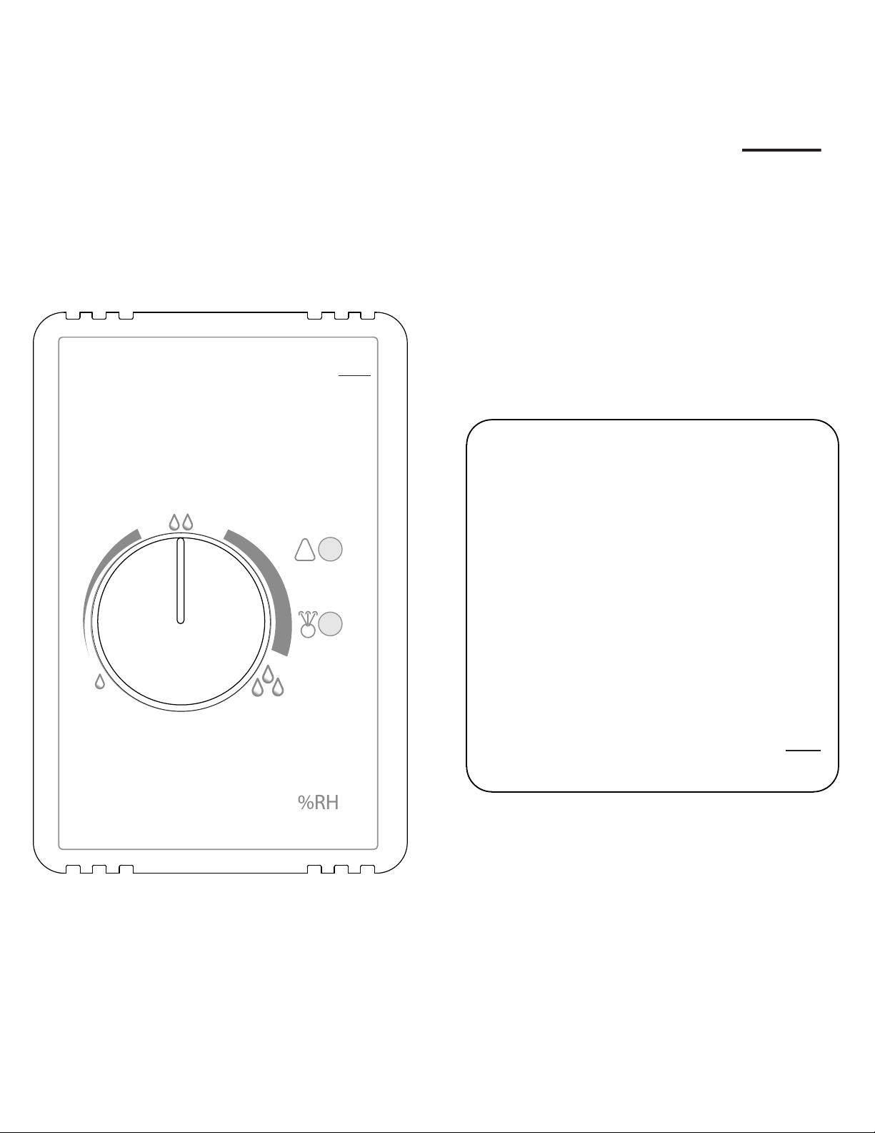
Fig. 1a Wall Mount Humidistat
Fig. 1b Back View of a Duct Mount Humidistat
1.2 A three wire control cable (not supplied) has to be connected between the wall (or duct) electronic
humidistat and the humidier electronic board at the three terminals marked “H-STAT”.
Please respect the sequence and connect
GND to GND 24V to 24V ST1 to IN
1.3 The outdoor sensor (please see Fig.1c) is supplied with the humidistat (wall or duct mount). It ideally
should be installed on an outside wall facing North. This outdoor sensor automatically reduces the setting
of the humidistat according to the outdoor temperature in order to avoid condensation on windows during
extremely cold days. It does the opposite during the mild days without your having to manually adjust the
humidistat. The outdoor sensor is a 10 kilo-ohms NTC thermistor (negative temperature coefcient).
Page 4

1.4 A two wire control cable is required to connect the outdoor sensor to the terminals marked COM & ODR
Fig. 1d
Baseplate Frontplate
on the electronic humidistat. Please see Fig. 1d. The outdoor sensor is not polarized so there is no wiring
polarity to follow.
To Humidifier
GND 24V IN
GND 24V ST1 COM ODR
GND 24V ST1
GND 24V ST1 COM ODR
From Outdoor Sensor
COM ODR
Red LED - Warning light, flashes when abnormal conditions occur
Green LED - Lit when humidistat is calling for humidity
Jumper - MUST be removed when outdoor sensor is connected
- remains in place if the outdoor sensor is not used
COMFORTSTEAM
H U M I D I F I C A T I O N S Y S T E M
Red
LED
Green
LED
30
20
35
50
40
!
Red
LED
Green
LED
IMPORTANT : Whenever an outdoor sensor is connected to the electronic humidistat, the jumper located at
the top of the electronic board must be removed so that the outdoor sensor becomes operational (i.e.
the jumper short circuits the terminals dedicated to the outdoor sensor). If the outdoor sensor is not installed,
keep the jumper in place.
1.5 If you decide to use a duct mount humidistat, it has to be installed on the return duct. Please use
the drilling template printed at the end of these instructions. This duct mounting method allows a better
“average sensing” of all the air returned to the furnace, thus offering superior humidity control. However, since
the humidistat has pilot lights giving information about the humidier status, they may not be visible if the
humidistat is installed in the basement.
Three holes have to be drilled in the duct, two for screws (approx. 1/8” dia.) and one for sensing (approx. 5/8”
dia.). The humidity sensor is located in the rectangular opening visible at the back of the humidistat baseplate.
This location will prevent potential dust accumulation on the sensor. Please see Fig. 1b.
Warning : Before installing anything on a duct, always check that you are not about to cut or drill into an air
conditioning coil or electrical accessories.
Page 5

Drilling Template for Duct Mount Humidistat
5/8” dia.
 Loading...