

Page 1
QUICK START GUIDE
TECHNOLOGY
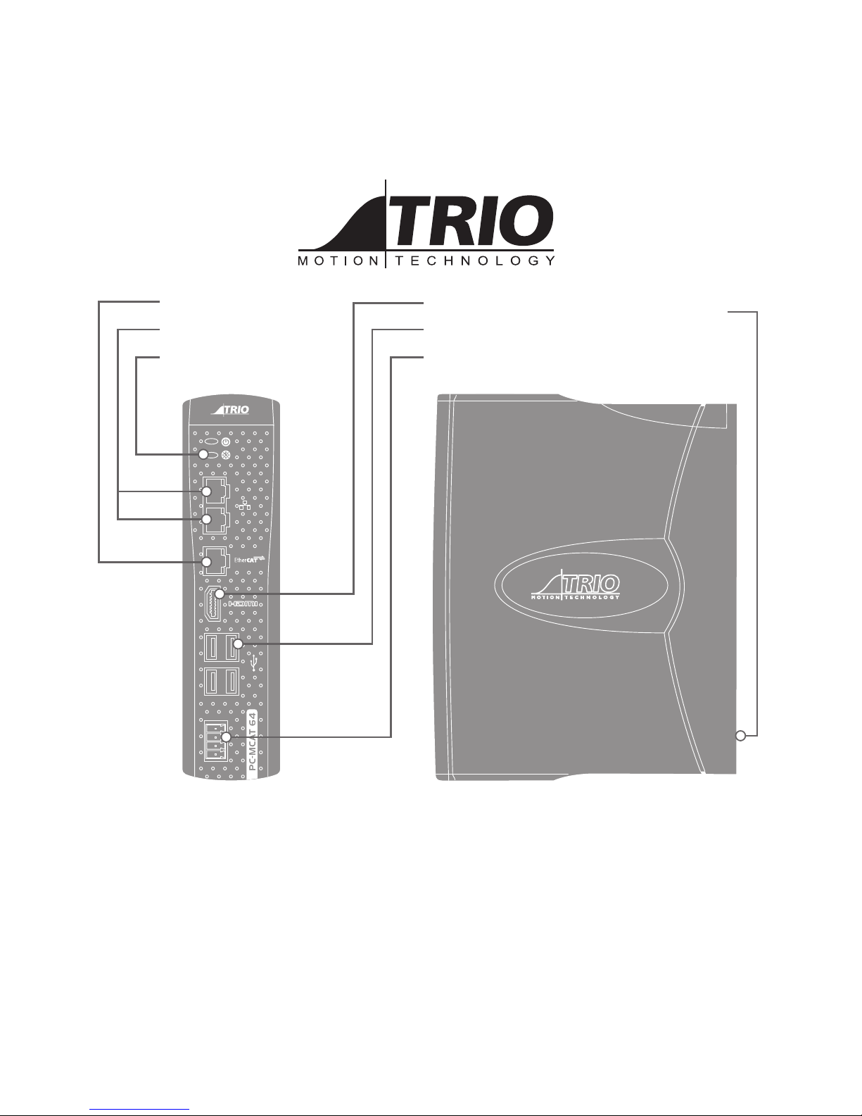
STATUS LED’S
ETHERCAT 100 BASE-T
USB (X4)
ETHERNET (GIG-E)
DUAL INPUT, POWER
HDMI OUTPUT
CHASSIS EARTH
SCREW
PC-MCAT 64
P760
Page 2

2
INTRODUCTION
The PC-MCAT combines a Windows® PC with the familiar and
powerful Trio Motion Coordinator core software. Using a
Quad Core ARM processor, the Motion Coordinator rmware
runs in real time with performance that is at least double that
of the equivalent MC4N-ECAT EtherCAT stand-alone Motion
Coordinator. This guide will take the user from initial power
up to programming and setup of the PC-MCAT in a typical
application.
It is assumed that the reader has some experience
with Windows and the Motion Perfect V4
programming application from Trio Motion
Technology.
EQUIPMENT
In addition to the PC-MCAT, the user will need the following;
• USB keyboard.
• USB mouse or trackball.
• An HDMI monitor and HDMI connecting cable.
• A 24V d.c. power supply rated at 2 Amps.
INITIAL CONNECTIONS
Plug the HDMI lead into the HDMI socket on the front face of
the PC-MCAT. Connect the other end to a suitable monitor
display.
Plug the Keyboard into any of the available 4 USB sockets on
the front of the PC-MCAT.
Plug the mouse into one of the USB sockets on the front of
the PC-MCAT.
Do not connect peripheral devices to the USB socket on the
upper face of the PC-MCAT.
INTERNAL BATTERY
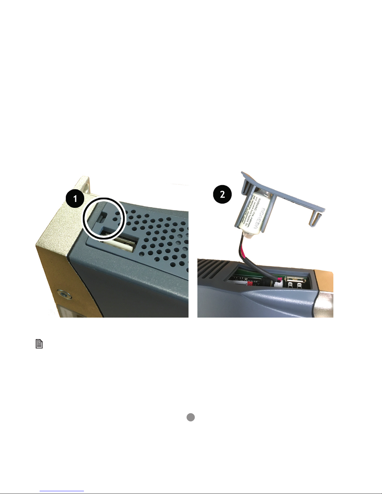
A PLC type battery is provided inside the top cover of the
PC-MCAT 64. This battery powers the Real Time Clock and
holds the PC’s bios settings. The battery lasts approximately
8 years and can be replaced while the PC-MCAT is powered to
preserve the settings.
0
SAFETY WARNING
During the installation or use of control systems, users of Trio products must ensure that there is no possibility of injury to any
person or damage to machinery.
Control systems, especially during installation, can malfunction or behave unexpectedly. Bearing this in mind, users must
ensure that even in the event of a malfunction or unexpected behaviour, the safety of an operator or programmer is never
compromised.
Page 3
3
BATTERY REPLACEMENT
1. Obtain replacement battery from Trio
2. Insert at bladed screwdriver to cut-out shown in image 1
3. Compress the “lug” on the batter y cover
4. Gently lever the battery cover up and forward
5. Lift away the cover taking care not to damage the wiring or case shown in image 2
6. Remove 2 pin connector from the PCB in the PC-MCAT
7. Remove battery from the battery cover
8. Reassembly is the reverse of the procedure
If the battery is disconnected at any time when the PC-MCAT is unpowered it is essential to reset the clock and bios.
The clock and date must be set to the correct values. These are used during RTX operation so must be correct.
Page 4

4
BIOS SETTING
• Under “Setup Utility” -> ”Thermal Conguration” set Critical Trip Point and Passive Trip Points to <Disabled>. This is because
the processor temperature is monitored by the real time Motion Coordinator.
Ther mal conguration Parameters
Critical Trip Points <Disable d>
Passive Trip Points <Disabled>
Active Trip Points <Disabled>
Dynam ic Platform & Ther mal Fram ework
DTPF Featire <Disabled>
CPU Sensors
Critical <70 ºC>
Passive <60 ºC>
Am bient Sensor Participants
Critical <60 ºC>
Passive <43 ºC>
• Under “Setup Utility” -> ”Boot Conguration” set Numlock to <O>. This is because setting to On can aect the entr y of
Windows user passwords on small keyboards.
Page 5
5
CONNECTORS
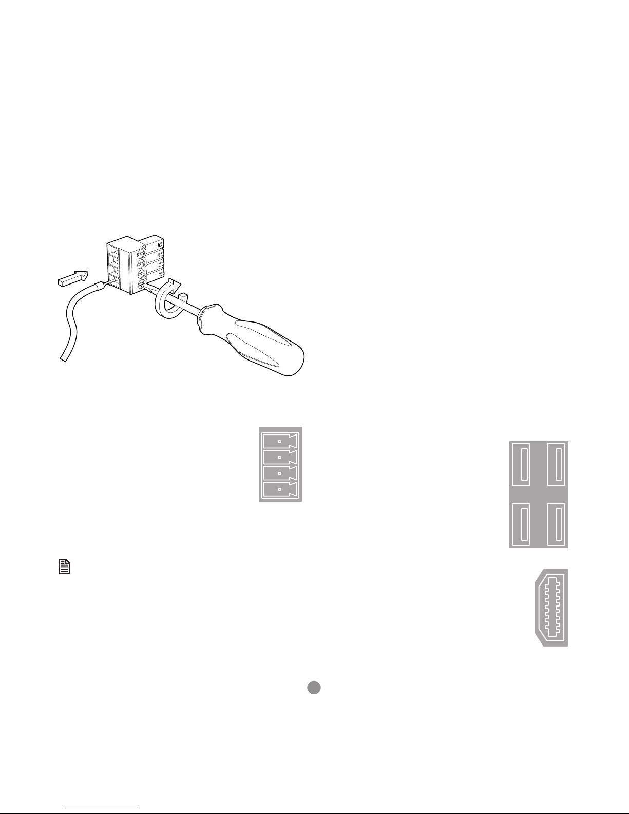
Dual Input / Power connector:
Note: Use ferrules on all wires for best connection.
1. Connection: Push wire into hole of connector. Tighten
screw. Insert connector into PC-MCAT.
2. Removal: Reverse the procedure.
POWER CONNECTOR
The 24V Main connection, pin
2, is the primary supply to
the PC-MCAT. The 24V Main
connection is monitored and
when it drops below 18V, IN(0)
is set to ON. This can be used
as a trigger to run a controlled
shutdown of the PC-MCAT.
If a controlled shutdown is
required, then the Aux (pin 1) must be connected to a battery
or other maintained source that lasts for the length of time
needed to complete the shutdown.
The Aux power input can be between 12 - 24V
POWER UP SEQUENCE
The PC-MCAT 64 will automatically boot into Windows
Embedded with RTX real time running. The default password
“trio” for default user “Trio” needs to be entered.
The Motion Coordinator program will be run as a service using
the RTX real time executive automatically.
If the RTX is not required the boot sequence must be altered
to bypass running RTX during the startup sequence.
POWER DOWN SEQUENCE
A controlled power down sequence should be used to avoid
damaging Windows and to allow the machine to complete a
cycle.
Windows should be shutdown using the command EX(2) inside
a Motion Coordinator program. Alternatively EX(3) can be
used to re-start Windows. Using EX(2) allows the Motion
Coordinator ser vice to be closed then Windows to shutdown.
This process takes about 30 seconds.
Input 0 can be used to detect the main 24v power supply
rail if an auxiliary power supply (12-24v) is provided from a
battery or UPS.
Input 1 is used by Windows to indicate to the Motion
Coordinator that a Windows shutdown has been requested.
USB PORT (X4)
The USB ports on the front panel are for use
with standard Windows peripheral devices.
If a keyboard and mouse are used, connect
them to 2 of these ports.
HDMI PORT
The HDMI port allows cthe PC-MCAT to drive high
resolution screens.
Aux 12 - 24V
Main 24V
0V
0V
Page 6
6
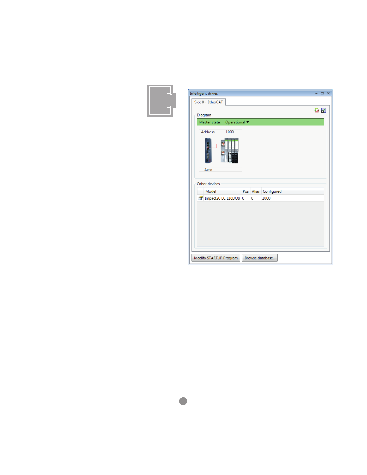
ETHERCAT PORT
The PC-MCAT acts as an EtherCAT master.
EtherCAT drives and I/O devices are normally
connected in a chain.
ETHERCAT OPERATION
All motion and Input/Output physical connections are via the
EtherCAT port on the PC-MCAT. There is no local I/O but the
Inputs 0 to 15 and Outputs 8 to 15 are reserved for internal
use by the PC-MCAT system. This means the external I/O
aligns with other Motion Coordinators that do have their own
I/O.
PLUG AND PLAY
The PC-MCAT comes with an internal database of EtherCAT
slave denitions. This allows many well-known devices to be
connected and automatically congured by the PC-MCAT on
star tup.
NETWORK TOPOLOGY
EtherCAT networks are logically one string of devices.
Connect the Master to the rst slave IN connection, then the
OUT of the rst to the IN on the second and so on. There is
no return cable, the last slave device automatically sets its
OUT socked to be a terminator.
Star and branch topology is possible using an approved
EtherCAT hu b.
0
STANDARD ETHERNET HUBS AND SWITCHES DO NOT
WORK WITHIN AN ETHERCAT NETWORK.
The EtherCAT port is automatically congured for use by the
Motion Coordinator when it starts up. It can be viewed from
the Windows Network “Change Adapter Settings” window.
In Windows, the EtherCAT port is shown as Disabled. This is
correct and must not be changed.
ETHERCAT NETWORK DETECTION
EtherCAT Intelegent drives Window in Motion Perfect
Page 7
7
NETWORK SETUP
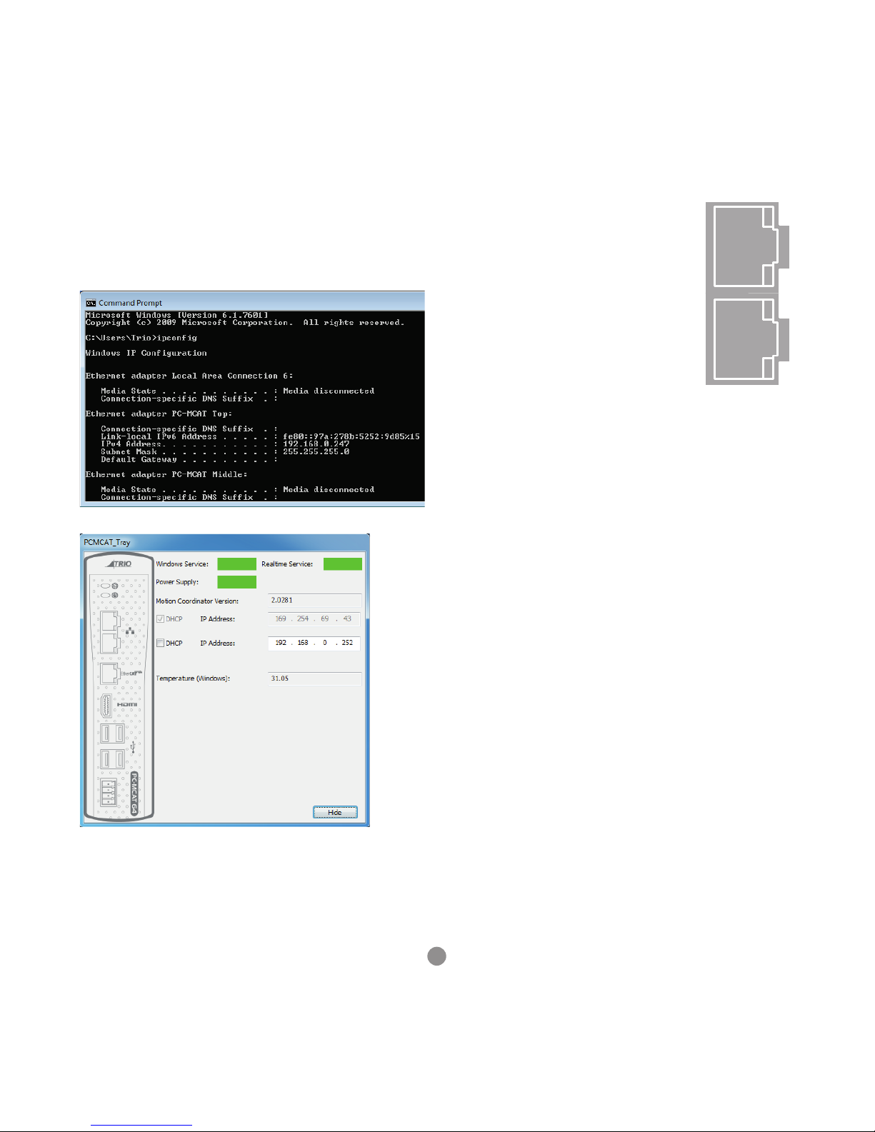
If the PC-MCAT is connected to a network, its IP address may
be given by the network DHCP address server. Use the
windows command line to discover the IP address given, or
check the PC-MCAT tray application.
OTHER PORTS AVAILABLE
All communication with the Motion
Coordinator in the PC-MCAT is through the
given Windows IP address. There is no
function to set IP_ADDRESS on the PC-MCAT
Motion Coordinator. Any external device
that wants to open a Motion Coordinator
Server connection must do so using the
Windows IP address for the connection.
There are 2 Ethernet connections
available; each has its own IP address
conguration in Windows.
Ethernet Server connections on the Motion
Coordinator:
• Port 502 - Modbus TCP
• Port 2222 - Ethernet IP (ODVA Industrial Protocol) UDP
connection
• Port 44818 - EtherNet/IP explicit messaging
• Port 3240 – TrioPC Motion ActiveX
• Port 23 - Motion Perfect connection
Many Windows services provide server functions and have
port numbers allocated according to the Internet Assigned
Numbers Authority. (IANA) Clients that open connections to
these port numbers will be communicating with a Windows
Application and not the Motion Coordinator.
Any application running in the PC-MCAT itself must use the
internal IP address 127.0.0.1 to communicate with the Motion
Coordinator. For example a Modbus Client running in the PCMCAT will use 127.0.0.1 and not the IP address of either of the
physical Ethernet connections.
RUNNING MOTION PERFECT ON REMOTE PC
Connect the PC to the PC-MCAT Ethernet port, either directly
with a xed IP address on both the PC and the PC-MCAT, or
via a network with automatic IP address control.
Close the Motion Perfect v4 that is running in the PC-MCAT.
You can now use Motion Perfect v4 to on the remote PC to
connect to the Motion Coordinator in the PC-MCAT. Motion
Perfect version 4.2 or later is required.
Page 8
8
PC-MCAT API
There is a shared memory API that allows Windows
programmes to interact with the PC-MCAT Motion
Coordinator.
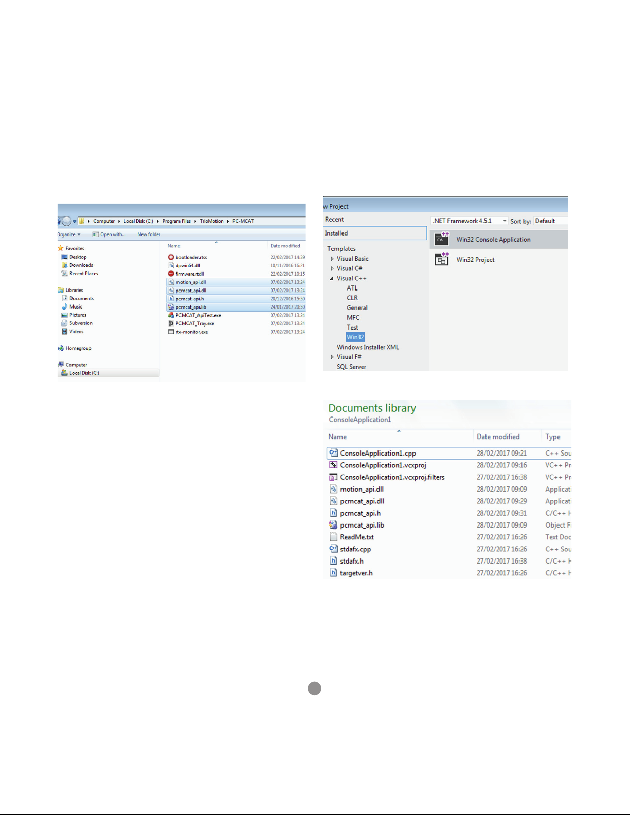
The API is installed in C:\Program Files\TrioMotion\PC-MCAT.
The PCMCAT_ApiTest.exe application uses the API to talk to
the Motion Coordinator.
The pcmcat_api.h le contains denitions that should be
included into your MSVC C/C++ source code. The pcmcat_api.
dll and motion_api.dll contain the implementation.
CREATING AN EXAMPLE WINDOWS CONSOLE
APPLICATION
1. Open Visual Studio version 2012.
2. Create a new C++ Windows console application.
3. Copy the API to the solution directory.
Page 9
9
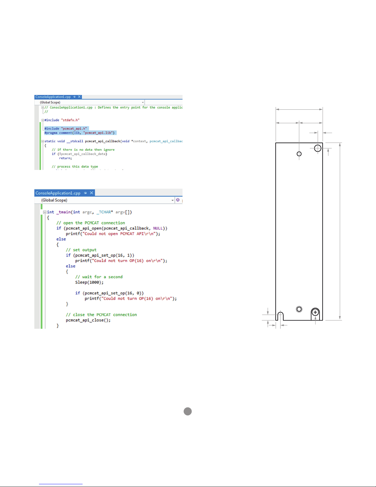
4. Add in the references to the API le.
5. Add the PCMCAT API calls.
CHASSIS MOUNTING DIMENSIONS (LOOKING FROM
FRONT)
M4 screws should be used
in 2 places to mount the
PC-MCAT to an unpainted
metal panel.
The best EMC performance
is obtained when the PCMCAT is attached from the
shield screw (marked) using
a at braided conductor
with a cross section of
4mm x 1mm. Do NOT use
a circular section wire or
run the braid to a central
star point.
0
ENSURE THAT THE VENTIL ATION SLOTS AT THE TOP
AND BOTTOM OF THE PC-MCAT ARE KEPT CLEAR
TO ENSURE A FREE FLOW OF AIR THROUGH THE
MODULE.
38.6
19.3 19.3
4
145.8
4
4.5
4.5
Shield Screw
Page 10
UK | USA | CHINA | INDIA
WWW.TRIOMOTION.COM
THE MOTION SPECIALIST
CAD data Drawings to aid packaging and mounting are available in various formats from the Trio web site. Products should be
wired by qualied persons.
Specications may change without notice. E & OE
Quick Start v1.1 March 2017
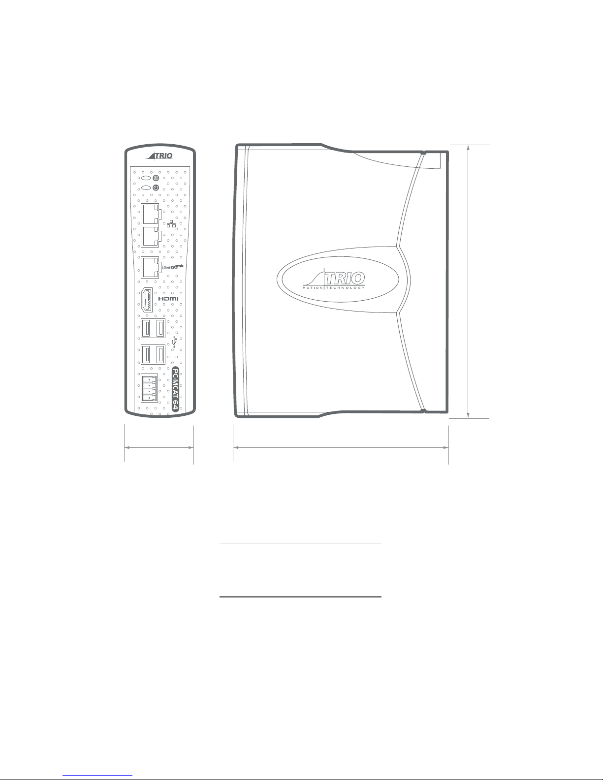
120mm
157mm
40mm
 Loading...