


MODEL TES18 & TES25
UV SYSTEMS
FOR RESIDENTIAL SPAS & SWIMMING POOLS
INSTALLATION & OPERATING
INSTRUCTIONS
TRIOGEN LTD. TRIOGEN HOUSE, CRAIGTON, GLASGOW. G52 1BD.SCOTLAND
TEL NO: (44) (0) 141 810 4861 FAX NO: (44) (0) 141810 5561 E-MAIL: info@triogen.com

ADVANTAGES OF UV OVER CHLORINE
The use of chlorine, in one form or another, has been the common method of
swimming pool water disinfection for many years. While not perfect, it has done a
reasonable job however various shortcomings of chlorine use have been, for the
most part, accepted as normal by the pool owning public.
We all know that water, if left untreated, will stagnate and a variety of microorganisms will flourish and cause health hazards. The same holds true if water is
not properly treated or under dosed with a sanitising agent. Therefore, in our pools,
we all strive for the best environment possible.
Are private pool owners successful in maintaining good quality pool water?
In general the answer has to be “no”, however our UV systems offer excellent
disinfection and protection. When one sees algae in pool water that is not clear and
sparkling, etched or green plaster, or the smell of chlorine is present in the pool, it
is easy to see that manual addition of chlorine is not necessarily the solution to a
safe pool water environment.
Automatic feeders, which constantly add small doses of chemical are not the
solution since fluctuations in bather loading, temperature changes, sunshine
(which dissipates chlorine) etc. are not taken into consideration.
So how does one ensure the health of those using the pool, without having specific
knowledge of chemistry or constantly tending to the pool water?
The answer is “Ultraviolet (UV) Sanitation”. This is the same technology used
worldwide in public swimming pools which see far higher bathing loads than the
typical residential pool. The TES range of UV units now make this technology
available at affordable prices for residential pools.
The units are easy to install, indoors or outdoors, and require only periodic thimble
cleaning and a once per year lamp replacement.
What are the advantages of using UV for pool sanitation over chlorine.
1. Consistent Sanitation Level
The TES UV system is ON and doing its job whenever the pool circulation is
operating. Thus, 100% of the pool water entering the UV reactor is sanitised before
returning to the pool
By contrast, chlorine is dosed into the pool at various times, for example, once or
twice a week. Thus, the pool is charged (when the chlorine is added) with a large
dose of chemical which then dissipates until the next dose. As a result, there is no
consistent level of chlorine. This can cause severe problems when the chemical
level in the pool is either too high or too low.
1
ADVANTAGES OF UV OVER CHLORINE
2. Elimination of “Chlorine Smell”
Chlorine exists in both a “Free state”, and a combined state in pool water. The Free
chlorine is the chlorine that is available to oxidise organics and kill bacteria. The
Combined chlorine is chlorine that is combined, or “locked up”, with nitrogenammonia compounds to allow the formation of Chloramines.
Chloramines are responsible for the chlorine odour that is normally present in a
“chemical only” treated pool. These chloramines exit the pool water in the form of
an off-gas that is not only unpleasant to the smell but has also been shown in tests
to cause skin, eye and respiratory problems, especially to asthmatic persons or
persons with other breathing difficulties.
Thus when Chlorimines are eliminated the “chlorine smell” disappears. UV has the
ability to produce a photo-oxidation effect that destroys chloramines and other
toxic by-products of chlorine. This results in much lower chlorine requirement for
bacterial control and greatly improves water and atmospheric conditions.
3. Hazardous Materials
When you add chlorine to a pool, extreme care must be taken not to overdose the
pool water and cause harm to the bathers. UV has the advantage over Chlorine in
that UV does not add any chemical to the pool water and cannot be overdosed.
4. Reduced Chlo rine Levels
A reduced amount of chlorine (70% to 85% reduction on normal usage) is still
necessary to oxidise the organics and for sanitising wetted areas such as in the
pool piping or filter. This level of chlorine is harmless.
5. Immediate Killing of Micro-organisms
While chlorine requires a long retention time of 20-45 minutes to sanitise, UV
sanitises the pool water in 1-3 seconds of exposure. This occurs during all
operation time of the pool circulation system.
6. Algae Control
Chlorine resistant algae, that normally require the addition of algae control
chemicals, are eradicated as they pass through the UV system. The cost savings is
obvious when these chemicals are no longer needed, but more importantly, your
pool begins to approach a more “chemical free” state.
7. Lower Operating Costs
Your pool operating cost is greatly reduced through the installation of the TES UV
system. Using less electricity than a 60 watt bulb, the system is one of the lowest
operating cost method of achieving high water quality.
2

DESCRIPTION OF EQUIPMENT
The TES range of low pressure UV systems has been designed for use on private
swimming pools and were developed to offer a cost effective disinfection system
for improved water quality.
The range consists of two sizes of UV units with flowrates of 18 and 25 M3/hr.
The UV reactor bodies are made from PVC plastic with an internal 316 stainless
steel reflector and a mirror polished stainless steel outer sleeve.
An electronic ballast with an operating indicator light powers the high output low
pressure UV lamp which has 9,000 hour bulb life.
Both units have 2” PVC inlet & outlet unions for easy installation into existing or
new PVC pipework with the addition of a pressure gauge on the top outlet
connection.
SIZING & SELECTION OF THE EQUIPMENT
The correct selection of the unit is imperative if the water is to be correctly
treated with a UV dose of 30mj/cm
2
which is the required does rate for effective
disinfection.
If the flowrates given below are exceeded then the contact time within the UV
reactor body will be reduced. This will have the effect of lowering the dose rate.
MODEL
REF
TES18
UV LAMP
WATTS
58
80
THE ABOVE FLOWRATES ARE BASED ON UV DOSE OF 30 mJ/cm2 AT END OF LAMP LIFE
FLOWRATE
M 3/HR
18.0
25.0TES25 200 150 100
POOL VOLUME - M 3
8 HOUR TURNOVER
144 108
POOL VOLUME - M 3
6 HOUR TURNOVER
POOL VOLUME - M 3
4 HOUR TURNOVER
72
To calculate the pool volume that can be treated, multiply the flowrate per hour
of the unit by the number of hours it takes to re-circulate the total pool contents.
In instances where the flowrates exceed the maximum allowed for each unit,
multiple units can be installed to satisfy higher flowrates.
3

INSTALLATION OF EQUIPMENT
The installation of the equipment should only be carried out by engineers who
are trained in fitting standard pool filtration equipment.
PRE-INSTALLATION CHECKS
The UV system can be either installed indoors or outdoors, if installing
outdoors protection from weather exposure should keep the unit in good
condition.
The unit has to be fitted in the pool filtrat ion pipework system and should be
located after filtration as shown in the diagram below.
It is recommended that isolating valves are fitted within the inlet and outlet
pipework when the unit is installed below pool water level to allow isolation of
the unit for periodic thimble cleaning or general maintenance.
It is also important to install the unit in an area that allows adequate height for
the removal of the reactor internal thimble or for UV lamp replacement. The
drawings below show the clearances required.
4

MECHANICAL INSTALLATION
The following installation guidelines should be read carefully and understood
prior to fitting the system.
1 - The TES units are supplied ready assembled with exception of the two inlet
and outlet half unions, union seals and pressure gauge.
2 - The bottom connection is the “INLET” connection and the top connection is
the “OUTLET” connection. Never reverse these connections.
3 - The bottom connection should be fitted with the solid half union tailpiece
and the top connection should be fitted with the clear tailpiece connection.
4 - Two white union gaskets are supplied with the units and care should be
taken to ensure that the gasket is installed with the raised half round bead
fitting into the tailpiece face which has a matching groove to correctly locate
the gasket within the union.
5 - Place the gaskets onto the face of the union tailpieces and then secure in
position by threading the half union nut on the TES unit onto the tailpiece.
NOTE: DO NOT OVERTIGHTEN THE UNION NUT.
HAND TIGHTENING SHOULD BE SUFFICIENT.
OVERTIGHTENING WILL BREAK THE UNION NUT.
6 - The TES unit is supplied with a pressure gauge which should be fitted into
the top clear union tailpiece. When installing the pressure gauge into the fitting,
only use the square bras s boss on th e back of the gauge when usi ng a spann er
but care should again be taken not to over-tighten the gauge.
NOTE: DO NOT OVERTIGHTEN THE PRESSURE GAUGE.
OVERTIGHTENING WILL STRIP THE PLASTIC THREAD.
DO NOT USE THE GAUGE BODY TO TIGHTEN.
The gauge should be fitted in a vertical position and never facing upwards as
water could enter the gauge and destroy it.
The gauge is used to indicate the pressure the pool pump is operating at and to
ensure that the maximum operating pressure of the TES unit of 40psi. is not
exceeded.
NOTE: DO NOT EXCEED THE MAXIMUM OPERATING PRESSURE
5

MECHANICAL INSTALLATION
7 - The TES unit should be mounted on a suitable concrete or wooden floor
structure and bolted down utilising the four bolt holes located in the unit base.
(Fixings not supplied)
NOTE: THE UNIT MUST BE SECURELY FITTED TO A FLOOR SURFACE.
FAILURE TO DO SO COULD RESULT IN VIBRATION IN
OPERATION AND STRESSING OF THE CONNECTIONS.
8 - The PVC pipework used for the installation should be glued into the union
tailpieces using suitable PVC primer and cement as recommended by the
pipework supplier.
9 - The connecting pipework ad jacent to the TES unit should be adequately
supported to ensure that no additional loadings are put on the reactor union
connections.
10 - The installation of suitable isolating valves is recommended for isolation of
the unit for maintenance and is mandatory if the unit is fitted below the pool
water level.
6

ELECTRICAL INSTALLATION
The electrical installation of the equipment should only be carried out by
suitably qualified person.
The TES UV unit is supplied with a three core flying lead. This should be
wired to a fused switched spur or fitted with an appropriate type plug for
connection to a socket.
The colour code in the lead is:-
Brown = 230V live line.
Blue = 230V neutral line.
Green/Yellow = Earth
This appliance must
be earthed.
The power consumption is:-
TES UV 18 - 58W (0.29A)
TES UV 25 – 80W (0.58A)
The plug or fused spur should be fitted with a 3A fuse.
The circuit for the socket / fused spur must be protected by an earth
leakage device such as an RCD or ELCB unless a plug is used that
incorporates an earth leakage device.
The power to the socket / fused spur must be interlocked with the supply to
the main circulating pump so that the power to the TES UV unit is isolated
when the pump is stopped and there is no water flow through the TES UV
unit.
In the case of a filtration system incorporating a time clock. As this will shut
down the main circulating pump the interlock on the power supply will
ensure that the TES UV unit is also swi tched OFF.
7

SYSTEM START-UP
The initial start-up of the UV system will depend mainly on how the system has
been installed but the following checks should always be carried out.
1 - Check that all pipework connections appear tight.
2 - Open both isolating valves which should be installed in the supply and return
pipe-work adjacent to the TES unit.
3 - This should flood the UV reactor body and then check for any water leakage.
4 - Start the main pool circulation pump and again check for any water leakage
now that the system is at operating pressure.
5 - Check the pressure reading at the TES unit pressure gauge to ensure that
the maximum pressure rating of 40 psi is not being exceeded.
6 - Check that the mains power supply to the unit is switched off and then
remove the top cap of the unit to allow inspection of the UV reactor thimble
and seal to ensure that there is no water leakage present.
7 - Re-instate the top cap.
8 - Switch on the mains power supply to the TES unit.
9 - The UV lamp should then be energised which will be indicated by a glow in
the top clear connection.
10 - When the power supply to the TES unit is electrically interlocked with the
main pool pump, stop the pool pump check that the lamp glow goes off.
Re-start the pump and check that the lamp energises again.
NOTE: IT IS ALWAYS PREFERABLE TO ELECTRICALLY INTERLOCK THE
POWER SUPPLY TO THE TES UNIT WITH THE MAIN POOL
CIRCULATION STARTER CIRCUIT AS A FURTHER SAFETY.
8
MAINTENANCE
The TES UV unit requires very little maintenance during the year, the required
maintenance is as follows:
UV LAMP THIMBLE CLEANING.
The UV lamp thimble which protects the lamp from direct contact with the pool
water must be kept as clean and free from external deposits as possible as
heavy contamination will effect the UV transmission through the quartz glass
into the water.
It is recommended that the quartz thimble is inspected at least every six
months.
To remove the UV lamp thimble, the following procedure should be adopted:
1 - Isolate the main power supply to the TES unit.
2 - Switch off the main pool recirculation pump.
3 - Close both the inlet and outlet isolating valves.
4 - Check that the pressure gauge reading has went to ZERO.
5 - If after a few minutes pressure still exists, release the top union nut which
will allow a little water to escape and the pressure should drop to ZERO.
Remember to re-tighten the nut.
6 - Remove the top electrical cover.
Depending on the time taken to reach this stage, the UV lamp may still be hot
and therefore the system should be left to cool down for at least ten minutes.
7 - Remove the UV bulb by pulling the lamp wire in an upwards direction until
the lamp plug and lamp end socket are visible.
8 - Hold the lamp only by the lamp end piece (not the glass) and remove the
lamp connection plug.
9 - It is now possible to fully remove the UV lamp taking care not to touch the
glass surface of the lamp as this could shorten the lamp-life if contaminated.
Always use clean cotton gloves or a cloth if handling the glass surfaces of
the lamp.
10 - Carefully store the lamp in a clean dry area while proceeding to the next
step.
11 - Remove the back plastic nut using a suitable tool that does not mark or
de-face the plastic material.
9

MAINTENANCE
UV LAMP THIMBLE CLEANING.
12 - After removing the plastic nut, the thimble water seal will be visible and
should be removed and stored safely.
13 - Grip the visible end of the glass thimble and pull upwards until the thimble is
fully removed from the reactor body.
14 - If staining or deposits are present on the outer surface of the thimble then
these can be removed by mixing a mild solution of muriatic acid (normally
available from pool stores) with water in a ratio of four parts water to one
part acid.
CAUTION: FOLLOW THE DIRECTIONS FOR USE AS STATED ON THE
SUPPLIERS BOTTLE AND ALWAYS PROTECT YOUR EYES,
WEAR RUBBER GLOVES AND AVOID BREATHIN G FUMES.
15 - If lime or hard water calcium deposits are encount ered, lime removal
products that are available for household cleaning may be used.
CAUTION: NEVER USE ABRASIVE PRODUCTS TO REMOVE DEPOSITS AS
THEY WILL DAMAGE THE SURFACE OF THE THIMBLE AND
DECREASE THE UV TRANSMISSION CHARACTERISTICS OF
THE HIGH QUALITY QUARTZ FROM WHICH THE THIMBLE IS
MANUFACTURED.
16 - After cleaning the outer surface, ensure that the thimble is completely dry
both externally and internally and also visually inspect the thimble for any
signs of cracking that could lead to premature failure while in operation.
17 - Re-insert the glass thimble into the reactor housing. The bottom end of the
thimble has to be located into a recess in the bottom cap. The thimble will
not go all the way down if it is not located into the recess.
18 - Place the black rubber sealing ring all the way inside the black plastic
sealing nut with the angled edge of the sealing ring facing downwards when
the nut is installed on the sealing gland.
CAUTION: DO NOT ATTEMPT TO FIT THE SEAL ONTO THE THIMBLE AS
THIS WILL NOT EFFECT A PROPER SEAL.
19 - Screw the plastic sealing nut onto the sealing gland taking care not to cross
thread the parts. Tighten gently with a suitable tool taking care not to overtighten.
CAUTION: OVER TIGHTENING WILL CRACK THE PLASTIC SEALING NUT
AND WATER LEAKAGE WILL THEN OCCUR.
10
MAINTENANCE
UV LAMP THIMBLE CLEANING.
20 - Open the TES unit isolating valves which should flood the reactor body with
water and check for any signs of water leakage around the thimble seal.
21 - Re-start the main pool circulating pump to pressurise the system and check
that the pressure gauge returns to its normal reading. Re-check the thimble
water seal for any signs of leakage.
22 - If water leakage occurs, gently tighten the nut another quarter turn to see if
this cures the problem. If not, the water seal ring may be out of alignment
or damaged and therefore the system will need to be isolated as previously
explained and the seal examined and replaced if required.
23 - Once it has been established that the water seal is correct, the pool
circulating pump should be stopped.
24 - Fit the lamp end cushion to the bottom end of the lamp and replace the top
two o-rings around the top ceramic lamp end (the end with the power pins)
Take care not to touch the glass surface with bear hands.
25 - Slide the lamp into the glass thimble taking care that the top two o-rings
remain on the lamp ceramic end and go into the glass thimble. These orings are only to avoid vibration of the lamp and are not water seals.
26 - Re-connect the UV lamp power plug to the ceramic lamp end piece ensuring
that the power plug is correctly orientated to the lamp pins as the plug will
only fit in two out of four directions.
27 - Refit the reactor top cap by using the screws provided taking care not to
over-tighten.
28 - Re-instate the mains power supply to the unit but the UV lamp should not
light at this stage as the main pool circulating pump should still be stopped.
29 - Re-start the main pool circulation pump and the UV lamp should illuminate
which will be indicated again by a glow at the top clear outlet connection.
The unit should now be fully operational again.
CAUTION: IT IS IMPERATIVE THAT THE MAIN POWER SUPPLY IS
ISOLATED WHEN THE REACTOR TOP CAP IS REMOVED AS
THIS ENSURES THAT EYE OR SKIN EXPOSURE TO UV IS NOT
POSSIBLE.
CAUTION: UV LIGHT CAN SERIOUSLY DAMAGE EYESIGHT OR SKIN.
11

MAINTENANCE
UV LAMP REPLACEMENT.
The TES UV lamps have a useful lamp life of 9000 hours of continual use. This
equates to approx. one years continual operation.
It is very important to note when the system was initially started up and how
many hours per day the lamp is in operation as this can then be used to
calculate when the 9,000 hours has expired and lamp replacement is necessary.
CAUTION: DO NOT EXCEED THE 9000 HOUR LAMP LIFE AS THE LAMP
REMAINING LIT IS NOT AN INDICATION THAT IT IS STILL
CAPABLE OF DOSING THE NECESSARY LEVELS OF UV
READIATION.
To remove the UV lamp, the following procedure should be adopted:
1 - Isolate the main power supply to the TES unit.
2 - Switch off the main pool recirculation pump.
3 - Close both the inlet and outlet isolating valves.
4 - Check that the pressure gauge reading has went to ZERO.
5 - Remove the top electrical cover.
Depending on the time taken to reach this stage, the UV lamp may still be hot
and therefore the system should be left to cool down for at least ten minutes.
6 - Remove the UV bulb by pulling the lamp wire in an upwards direction until
the lamp plug and lamp end socket are visible.
7 - Hold the lamp only by the lamp end piece (not the glass) and remove the
lamp connection plug.
8 - It is now possible to fully remove the UV lamp.
9 - Fit the lamp end cushion onto the bottom end of the new lamp and replace
the top two o-rings around the top ceramic lamp end (the end with the
power pins) Take care not to touch the glass surface with bear hands.
Always use clean cotton gloves or a cloth if handling the glass surfaces of
the lamp.
10 - Slide the lamp into the glass thimble taking care that the top two o-rings
remain on the lamp ceramic end and go into the glass thimble. These
o-rings are only to avoid vibration of the lamp and are not water seals.
11 - Re-connect the UV lamp power plug to the ceramic lamp end piece ensuring
that the power plug is correctly orientated to the lamp pins as the plug will
only fit in two out of four directions.
12 - Refit the reactor top cap by using the screws provided taking care not to
over-tighten.
13 - Re-instate the mains power supply to the unit but the UV lamp should not
light at this stage as the main pool circulating pump should still be stopped.
14 - Re-start the main pool circulation pump and the UV lamp should illuminate
which will be indicated again by a glow at the top clear outlet connection.
12
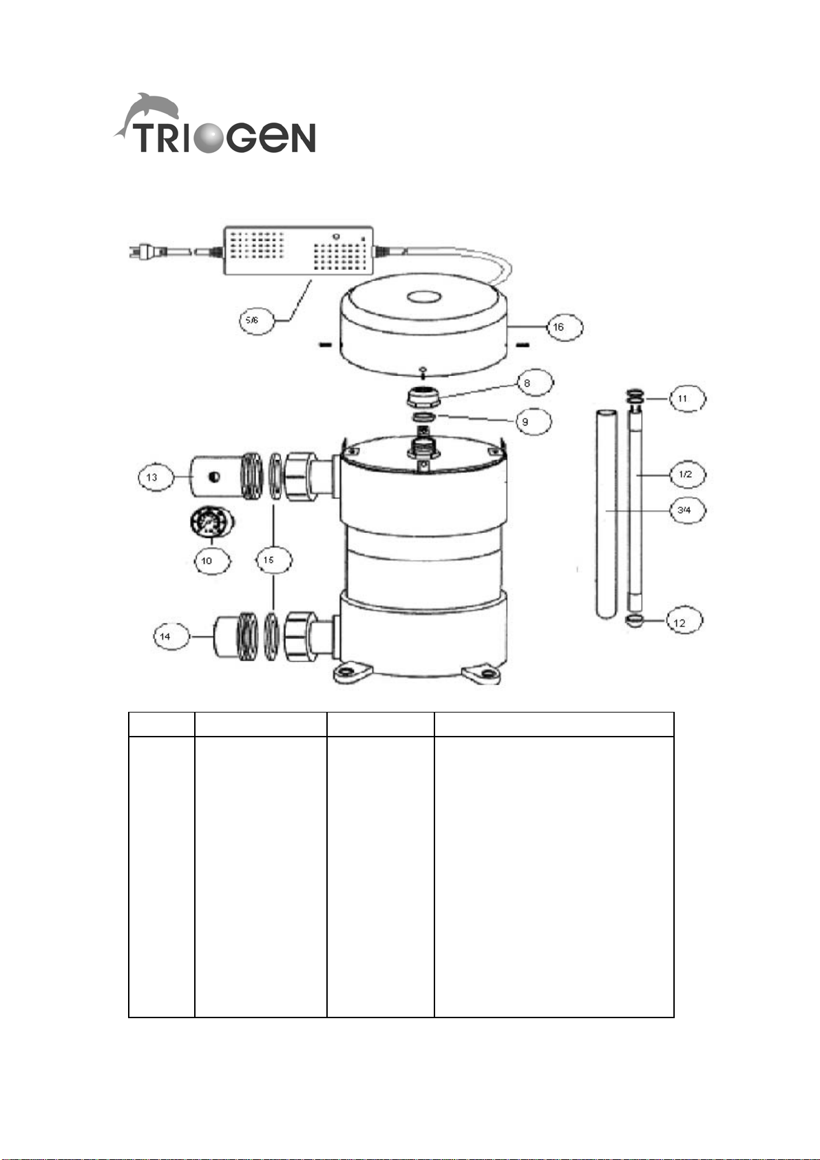
TES UV REACTOR PARTS
ITEM PART No. UNIT TYPE DESCRIPTION
1
2
3
4
5
6
8
9
10
11
12
13
14
15
16
TESP001
TESP002
TESP003
TESP004
TESP005
TESP006
TESP008
TESP009
TESP010
TESP011
TESP012
TESP013
TESP014
TESP015
TESP016
TES18
TES25
TES18
TES25
TES18
TES25
TES18-25
TES18-25
TES18-25
TES18-25
TES18-25
TES18-25
TES18-25
TES18-25
TES18-25
UV LAMP
UV LAMP
UV LAMP THIMBLE
UV LAMP THIMBLE
UV LAMP BALLAST
UV LAMP BALLAST
THIMBLE SEAL NUT
THIMBLE SEAL
PRESSURE GAUGE
O-RING VITON (2)
UV LAMP CUSHION
UNION TAIL PIECE (CLEAR)
UNION TAIL PIECE (WHITE)
UNION FLAT SEAL
ELECTRICAL TOP CAP
13
WARRANTY
The UV systems (UV reactor and electrical control panel)
are covered by a twelve month limited warranty period
starting at the date of purchase, during which time any
failure of the equipment due to defectiv e wor kmanship or
parts, will be rectified provided that:
1. Notice of the claimed defect is given to Triogen
within twelve (12) months from the document ed
date of purchase.
2. Following notification, the parts or accessories ar e
properly packaged and returned to the address so
designated by Triogen, and that associated
transportation and any other charges are prepaid.
3. Upon inspection, Triogen is satisfied that the
claimed defects are traceable to t he or iginal parts
or workmanship.
The warranty will be deemed void, if the equipment is
serviced by other than a tr ained service engineer
acknowledged by, or employed by, t he supplier, or if the
equipment has not been properly installed or operated
according to the instructi ons in this manual.
In no event shall Triogen be liable for any consequential
loss, damage or expense arising from the supply and use
of the equipment , either separately or in combination
with other equipment.
Triogen low pressure UV lamps are guaranteed for
up to 1500 service hours full replacement. Lamps
must be operated as specified, in a manner for
which they were designed and must be returned, as
noted above, for replacement lamp credit
determination.
14
 Loading...