

Page 1
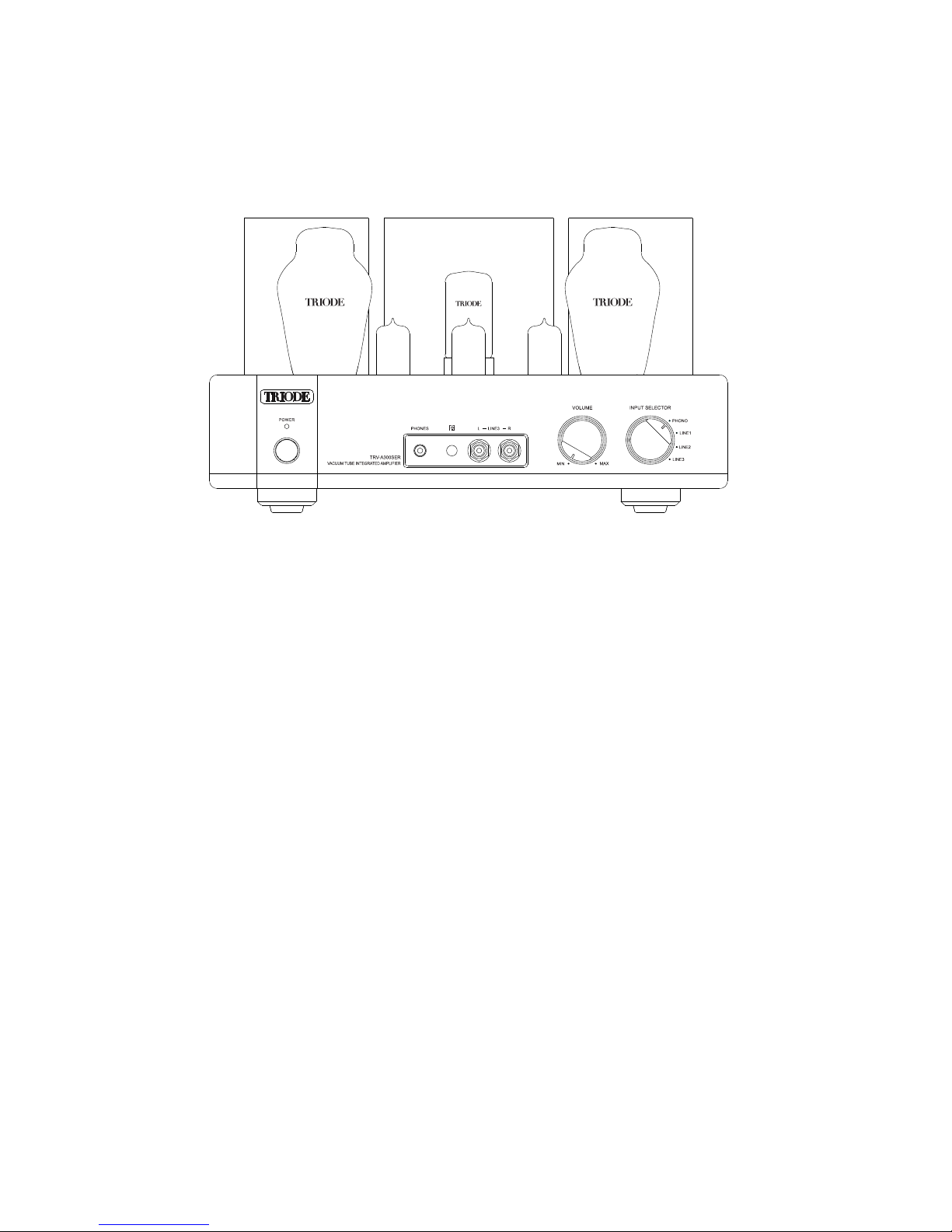
Vacuum Tube Integrated Amplifier
TRV-A300SER
Please read the manual carefully before installation and operation.
User’s Manual
12AU712AX712AU7
!""#!""#
5AR4
Page 2
Vacuum T Integ ratedube Amplifier
1
Table of Contents
Suggestions
Thanks for choosing our TRIODE TRV-A300SER Integrated Amplifier as an
important part of your music system and please read the manual carefully before installation
and operation.
In order to prevent damage during transportation the amplifier is packed with protective
foams surrounding the tubes. Before installation please remove these foams to avoid
any risks.
Vac uu m T u be
Rear Panel...........................................6
Remote Control Unit..............................7
9
10
11
....................................12
13
Installation..........................................8
Audio Connection.................................
Speaker Connection.............................
Turn On...............................................
Specification..
Troubleshooting..................................
Table of Conten t s...... ....... . ....... . ...... .
Overview From The Top.....................5
1
Package Contents........ ....................1.
Product Features...............................2
Safety Precautions...........................2
Warr a nty... . ... ... . ... ... ... . ... ... ... . ... ... . ... 3
Precautions.....................................3
Front Panel.....................................4
Integrated Amplifier is designed and manufactured
with our original parts and reaching the best results. We are not responsible for problems
and damages caused by non-original parts replacement in the amplifier.
TRIODE TRV-A300SER Vacuum Tube
Package Contents
Please carefully check the package first and then open the package. Package contents
include:
1. ..... 1
2. Main Fuses................... ......2
3. Power cord...................... ...1
4. User's Manual............... . .....1
Recommendation:
Keep all packing materials for future use.
Note:
Please ma ke sure local voltage level is matched with the input level of t he amplifier which
indicat es on the rear panel. Too low or too high voltage may cause p roblem and in case
you've fo und improper voltage please contact our company or our loc al agent.
TRIODE TRV-A300SER ..........
..........
..........
........ .
5.TRM-INT. Remote control unit......1
Page 3
2
Vacuum Tube Integrated Amplifier
Safety Precautions
Product Peatures
1. Unplug the power cord if you are not going to use the product for an extended period of
time.
2. Temperature will become higher after working in long period of time and please keep the
unit's ventilation open and install the amplifier at a well-ventilated place to avoid troubles
and fire hazard.
3. Forbidden to operate when the output is open or shorted.
4. Do not attempt to service this product yourself. Opening the cover may expose you to
dangerous voltage or other hazards.
5. We are not responsible for any problems caused by checking and opening without
permission of our company. For service, Please contact a qualified service technician.
6. Do not place any objects filled with liquids such as vases or some others on the top or
around.
7. Clean only with dry cloth.
8. Please move the amplifier carefully not to drop the unit or be subject to other strong
shocks.
◆
◆
◆
◆
◆
◆
◆
◆
class A
Hand-made construction with the finest point-to-point wiring.
Specially designed toroid transformer for power supply.
Two output transformers with wide bandwidth are applied.
Two s and one are used in the preamp stage.
Two tubes are used for amplification.
Headphone output jack has been used.
Easily installed Tube cover.
EI
12AU7 12AX7
300B
One piece of is used for high voltage rectification.5AR4
◆
◆
◆
◆
◆
◆
◆
◆
◆
◆
◆
RIS K OF ELEC TRIC SH OCK
DO NO T OP EN
CAUTION
To r e du ce th e r is k o f e le ct ri c s ho ck , d o n ot r em ov e t he c o ve r.
To r e du ce th e ri s k o f f ir e o r e le ct ro ni c s ho ck , d o n ot e xp os e
the unit to rain or moisture.
No user serviceable parts inside. Refer servicing to qualified
service perso nne l.
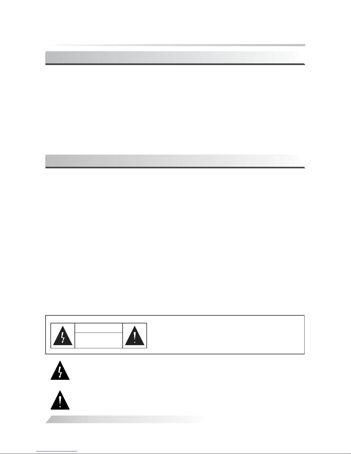
The exclamation point within an equilateral triangle is intended to alert the user to the
presence of important operating and maintenance (servicing) instructions in the
literature accompanying the appliance.
The lightning flash with arrow head symbol, within an equilateral tr iang le, is i nten ded
to alert users to the presence of uninsulated “dangerous voltage” within the product
that may be of a risk shock to persons.
Page 4
3
Vacuum Tube Integrated Amplifier
Warran ty
1. This product is warranted for a period of twelve months beginning from the date of
purchase.
2. The defective product must be returned to your dealer or our company for repairing when
your dealer or our company accepts your requirement.
3. The warranty doesn't extend to any product that has been opened by you without
permission of our company.
Note: The information i n this manual is subject to c hanges without notice .
Precautions
Connect to
AC Input
Connect to
AC Input
YALIDA
YN-401
◆
◆
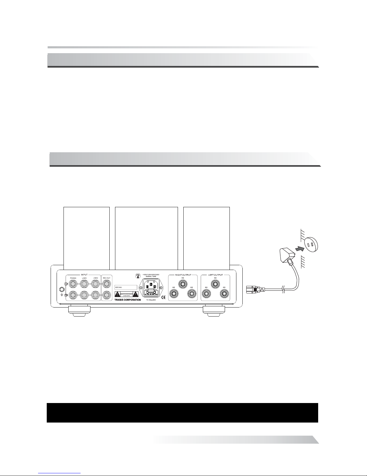
Connection of the power cord.
Connect the speaker cables and signal cables first and then insert the power cord into the
power socket.
◆
◆
Note: Connect the speaker cables and signal cables first and then insert the power
cord into the power socket.
Note
Warning
:
:
1. It is norm al that power transform er becomes hot for extended period of operation.
2. Please u nplug the power cord if you 're not going to use the product for an extended
period of t ime.
Please ma ke sure corresponding v oltage is the same as required. We are not
respons ible for damage caused by m isuse of unsuitable voltage.
Page 5
4
Vacuum T Integ ratedube Amplifier
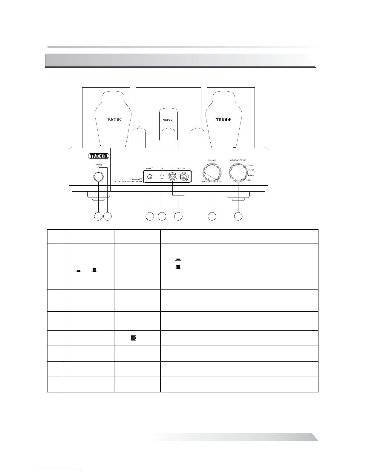
Front Panel:
①
②
③
Power
Indicator
Switch the amplif ier:
Switch on;
Switch off.
Note:Unp lug the power cord if you are n ot going to
use the prod uct for an extended perio d of time.
ON/OFF
ON
OFF
“”:
“”:
Power Swit ch
/()
ON OFF
Name Marks Description
Indicati ng the operation mode. If s witched on the
will keep li ghting.
LED
Headphone
Socket
Helping yo u enjoy the high-qualif ied music alone.
No.
1
3
4 5 6 7
2
④
⑤
⑥
⑦
Signal Inp uts Used for sou rce input(CD, AUX1,AUX2).
Volume Switch
Remo te Sens or
Window
Input Sele ctor
POWER
PHONES
INPUTS
VOLUME
INPT U SELEC TO R
Receivin g the remote signal.
Controll ing the mail volume
Selectin g the input signals
.
.
12AU712AX712AU7
!""#!""#
5AR4
Page 6
5
Vacuum Tube Integrated Amplifier
No.
300B
12AU7
12AX7
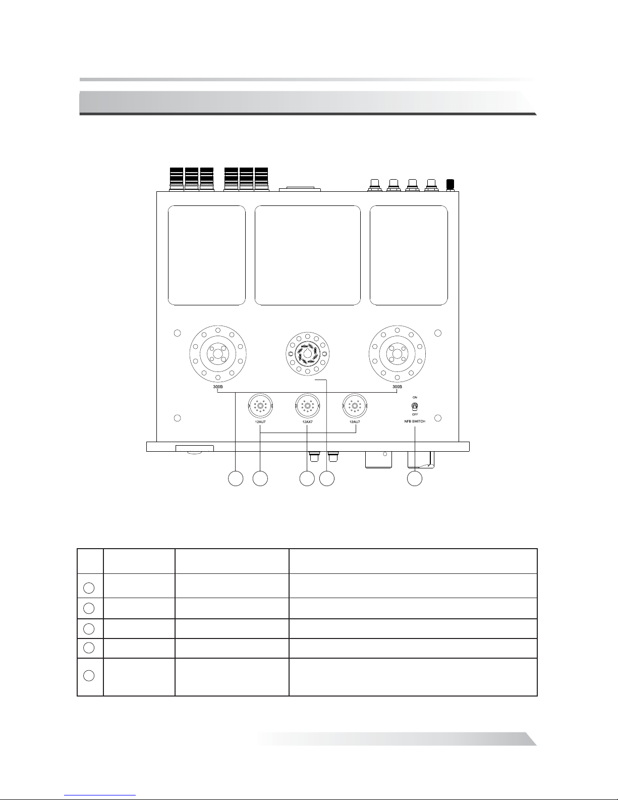
Overview From The Top:
Name
Sign Description
Power Tube 300B Power Tube
Twi n - Triode
12AU7 Drive Tube
Twi n - Triode
12AX7 Vo l ta ge A m p li f i ca ti on Tu b e
1
2
3
5AR4
4
1 2
3
4
Rectifier Tube
5AR4
5
5
NFB Switch
NFB SW ITCH( ON/OF F)
5AR4 Rectifier Tube
If Switch positions at the operation state is
-3dB while if positions at the operattion state is 0dB.
NFB ON NFB
OFF
Page 7
6
Vacuum Tube Integrated Amplifier
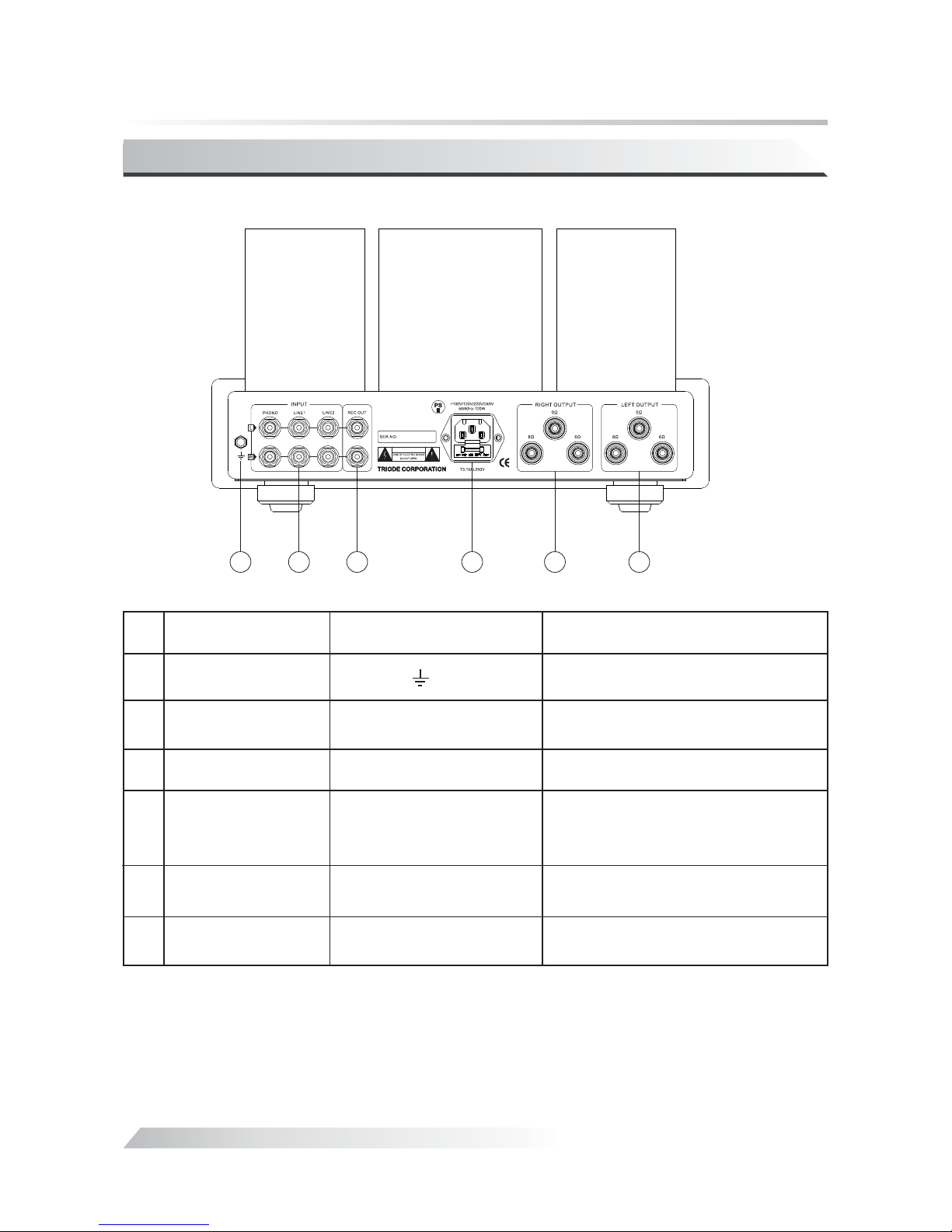
Rear Panel:
No.
①
②
③
④
⑤
INPUTS
RIGH T SP EAKER O UTPUT S
LEFT SPE AKER OU TPUTS
Name
Marks Description
Signal Inp uts
Used for sou rce input(PH ONO, LI NE1,
LINE2,LINE3).
Right Chan nel Output
Used to conn ect with the right
channel of t he speakers.
Left Chann el Output
Used to conn ect with the left
channel of t he speakers.
Power Sock et Wit h
Main Fuse
Main fuse is l ocated on the rear of the
amplifie r just below the power cord
socket. Re place with the same type
and value of f uses.
1 3 4
5 6
Used for sou rce outpu t
REC OU T
Recorder Output
2
⑥
Ground
Used to conn ect with the ground
.
.
Page 8
Vacuum T Integ ratedube Amplifier
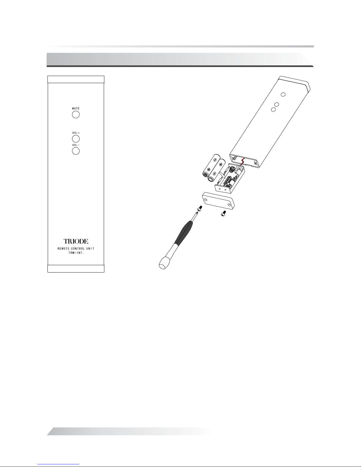
Remote Control Unit:
7
About the keys
1. “
MUTE”: Mu te button
2. “VOL+” : Increase the main volume
3. “VOL-” : Decrease the main volume
1 Handle th e remote control unit face downwards and screw open the rear cover wi th the
2 Pull out th e battery case carefully (do not break the wire connected).
3 Put in the tw o "AAA"(R03) batteries with correct polarity.
4 Push in the b attery case and screw close the rear cover.
How to inst all the batteries
attache d hexagon screwdriver.
Page 9
Vacuum Tube Integrated Amplifier
8
Installation:
Page 10
9
Vacuum Tube Integrated Amplifier
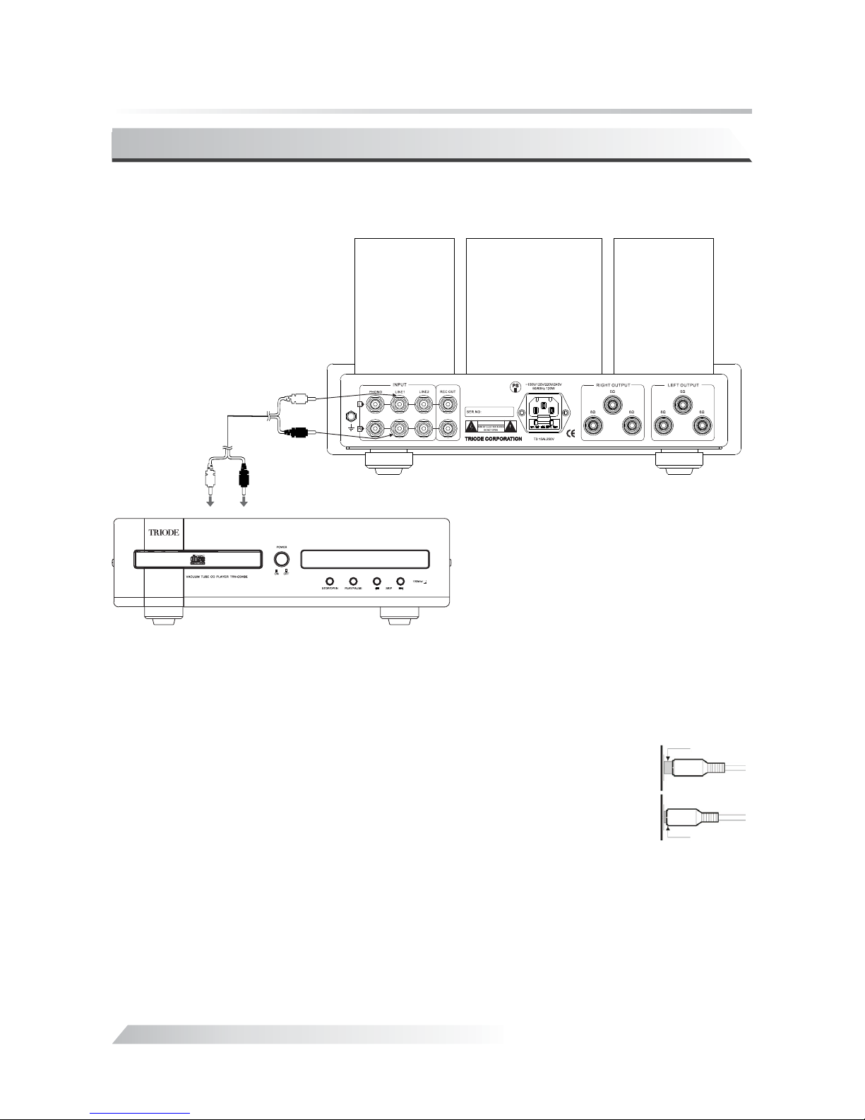
Audio Equipment Connection
Connection method of TRIODE TRV-A300SER with other audio equipments, take
pictures below for your reference:
Suggestions:
1. During installation please always refer to other products' operation
manuals.
2. Please do not insert the power cord into the main socket only if all other
instruments are well connected.
3. R refers to right channel while L represents left channel.
4. Please take the right guidance for connection as wrong connection may
cause noise or low grade function.
5. Do not fasten signal cables together with other cables just like the power
cables to avoid disturbance.
Correct
Incorrect
Page 11
Vacuum Tube Integrated Amplifier
10
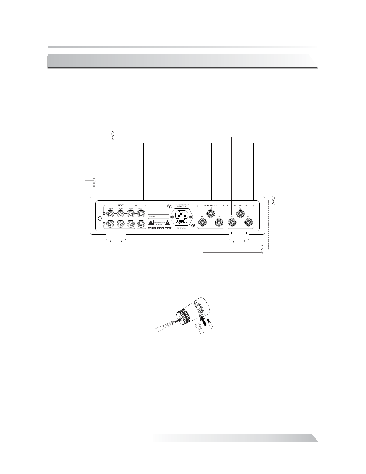
Speaker Connection
Banana plug
Normal plugNormal plug
speaker left()speaker left()
speaker right()speaker right()
black
red
black
red
◆
◆
Check the impedance of your speakers. Attach the positive from your speaker to the 6 or
8 ohm terminals and the negative to the 0 ohm terminals separately.
If your speakers are 4 ohm it
would cause damage to the amplifier. You can attach them to the 6 ohm terminals.not
6 ohm or 8 ohm impedance speakers are preferential.
◆
◆
How to connect the speaker cables:
1. Unscrew the terminal knobs,
2. Insert the speaker cables,
3. Screw the terminal knobs.
Note:
Connect t he speaker cables with the amplifier after it is well connec ted with the speakers.
Please no tice the right direction indication of the cable and do not mi x up the positive and the
negativ e end.
Page 12

11
Vacuum Tube Integrated Amplifier
Turning On
Before turning on the amplifier please make sure all connections are right and power supply
is stable.
1. Turn on the amplifier and the power LED will be on. It shines and indicates that the
amplifier is working.
2. In 30 seconds the power LED will keep lighting up. It means the amplifier functions very
well. Or if the LED is not on please contact with our local agent or our company.
3. Select the right sound source, adjust the volume to a certain position and then you can
enjoy the music you prefer.
Note:
1. Forbid den to insert or pull out the signal cable and speaker cables du ring operation, in
case that i t will do damage to the machine or other equipments.
2. Switch o n the amplifier once again in at least two minutes if the unit has b een shut down
, in case tha t it will do damage to the vacuum tubes.
Page 13
Vacuum Tube Integrated Amplifier
12
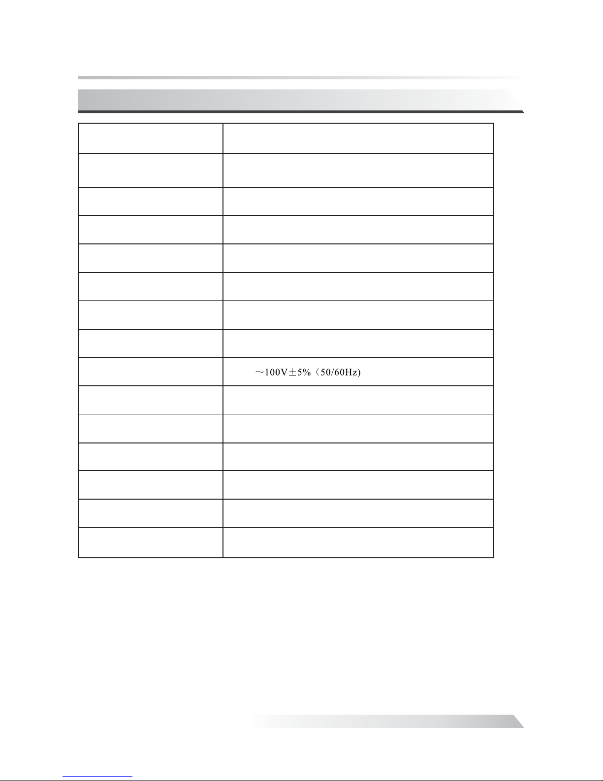
Specifications
Power Outp ut
THD
S/N Ratio
Input Sensitivity
Input Impedance
Output
Impedance
Vo lt ag e
Dimension
Tube
Net Weig h t
Power Cons umption
Max
Working Condi tion
Storage Co ndition
~()15Hz 35kHz -3 dB
.05%
83 dB
320 mV :2.5mV
PHONO
100 ΩK
,68ΩΩ
()342 320 200 mm
3
XX
、、12AX7 1 12AU7 2 5AR4 1XXXX、300B 2
15kg
120W
Temperat ure: 0 40
Moisture : 20% 80%
℃~~℃
~
~
Temperat ure: -20 70
Moisture : 20% 90%
℃℃
Specification
Frequency
Response
Item
:47KPHONO Ω
8W+8W
Page 14
13
Vacuum Tube Integrated Amplifier
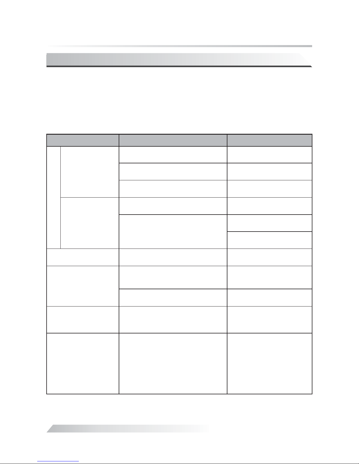
Troubleshooting
Problem
Cause
Remedy
NO OUTPUT
Power is .LED OFF
Power is .LED ON
Sound Distortion
Noise output
Sound field Positioning
is not so good.
Power cord i s not well-connected.
Main fuse is o ut.
Tro ubl es of i nne r parts or components.
Volume is at .ZERO
NO
signal inp ut.
High input s ignal level.
Ground of in put signal cable is open
or bad conta ct of the input signal
cable.
Components or c ircuits are in trou ble.
Signal inp ut cables or speaker
cables are w rongly connected.
Check power cable connection
or power outlet connection
Replace wi th the same type
and value fu se.
Please con tact with local
agents or ou r company.
Tur n up the Volume.
Check the fu nction of the
sound sour ce.
Check the input s election and
switch to the pro per input.
Tur n down the volume to
suitable p osition.
Replace th e input signal
cable with a n ew one.
Please con tact with local
agents or ou r company.
Reconnec t it as suggested in
the manual .
Please follow the instruction in the manual in order to keep the amplifier work in its
best state. If wrongly operated and you thought that would be troubles please check
according to following tips to look for the exact reason. Sometimes problems would be
caused by the other related products and please have a check too on those connections.
Even doing so, if the problem still exists please contact with your local agent or our
company.
The functi on of the
remote con trol unit
is not sensi tive.
Somethin g disturb s in the
surround ings. For e xample,
strong flu orescent lamp.
The batter ies have notenough powe r.
There are ob stacles between the
remote con trol unit and the player.
Leave the di sturbing source.
Change the b atteries.
Remove the o bstacles.
 Loading...