

Page 1

Triode Electronics
ST70 Kit
INSRUCTION MANUAL
Rev. 1 2007
Page 2
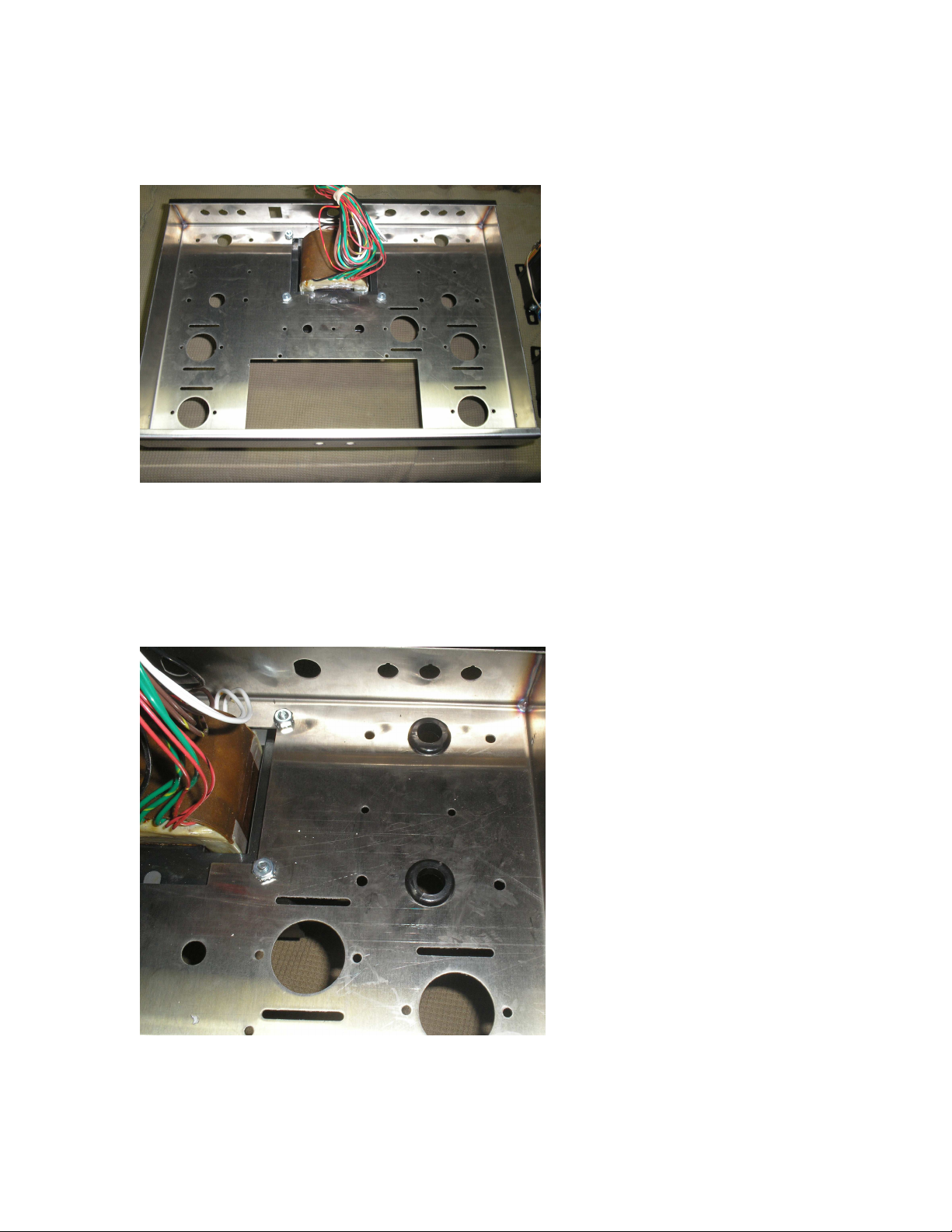
Step 1: Mount the power transformer into the chassis using 8-32locknut
Step 2: Mount Rubber grommets for output transformer leads
Page 3
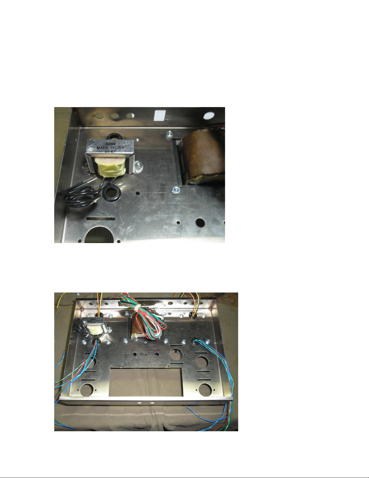
Step 3: Mount Rubber grommets for other output transformer and install C354 choke using 6-32 bolts and
locknuts
Step 4: Mount output transformers into chassis using 8-32 bolts and lock washers, run leads through
grommet holes into chassis.
Page 4
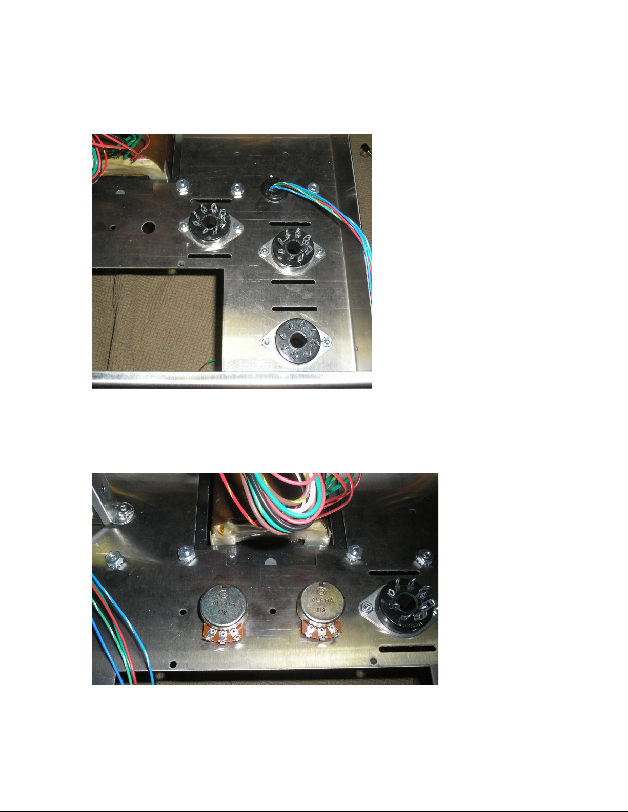
Step 5: Mount Octal sockets for EL34 tubes and 5AR4 tube into chassis using 4-40 bolts and nuts
Step 6: Install 10k bias potentiometers into chassis
Page 5
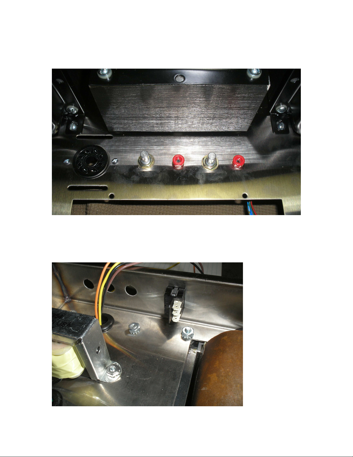
Step 7: Install bias test points next to bias potentiometers
Step 8: Install power switch into back panel of chassis
Page 6
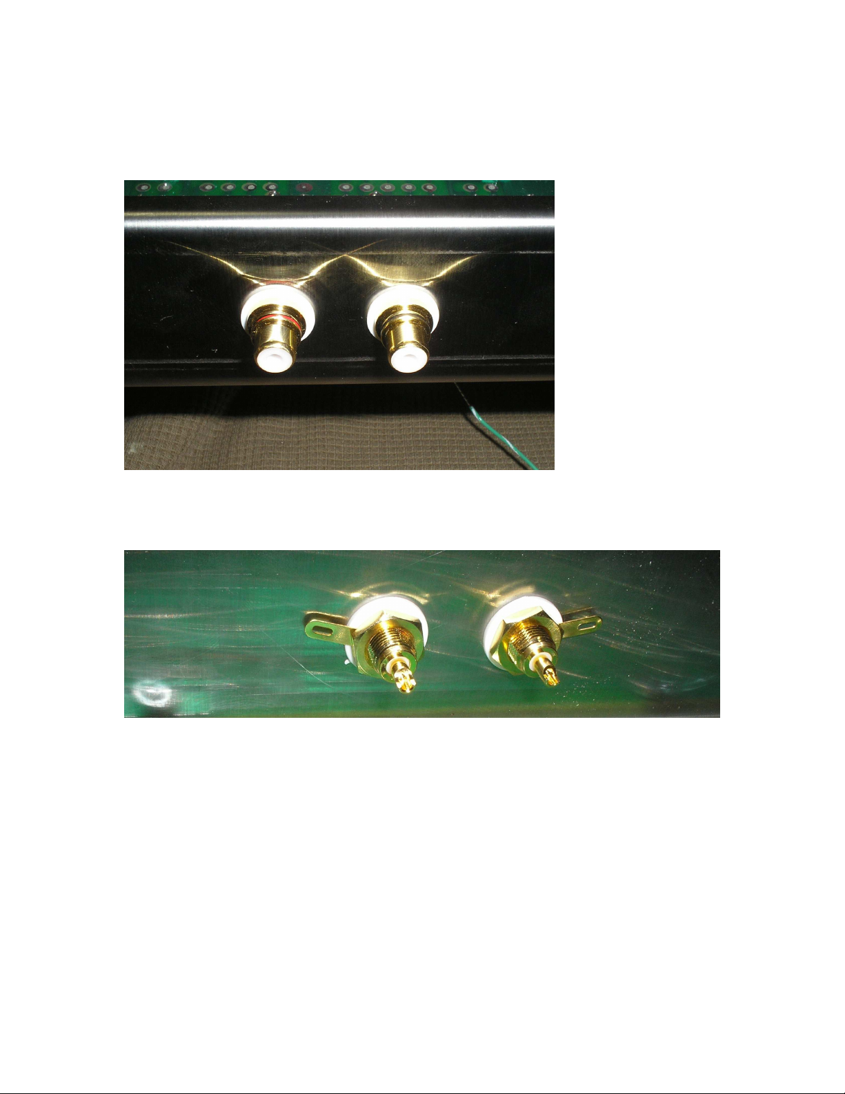
Step 9: Install Gold Insulated RCA Jacks into the front panel of the chassis:
Page 7
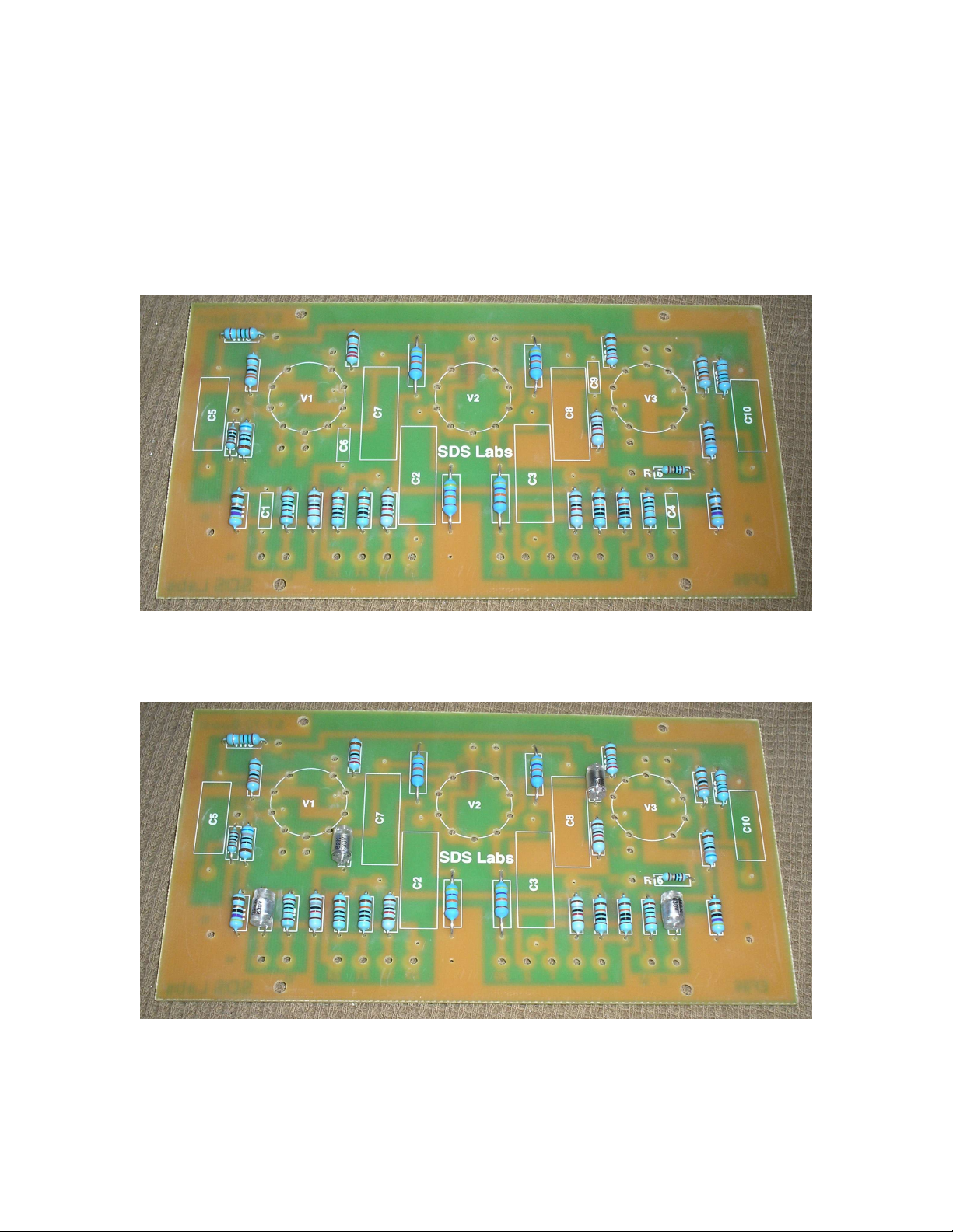
Step 10: Build and Install the Driver PCB board into the chassis
A. populate resistors onto board
B. Populate Polystyrene Capacitors onto board
Page 8
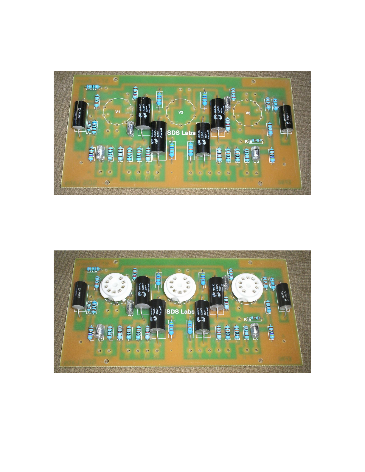
C. Populate Coupling Capacitors and Screen Bypass Caps onto board
D. Solder PC mount sockets onto the board
E. Install Built driver board into chassis using 4-40 bolts and nuts
Page 9
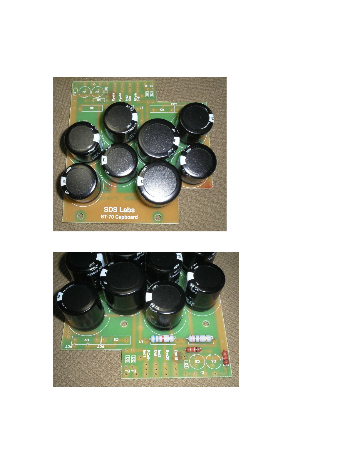
Step 11: While we’re at it lets go ahead and put together the SDS Labs capacitor board so it will be ready
for later
A. Install Snap in Capacitors into the board and solder in place
B. Install Resistors on top side of board
Page 10
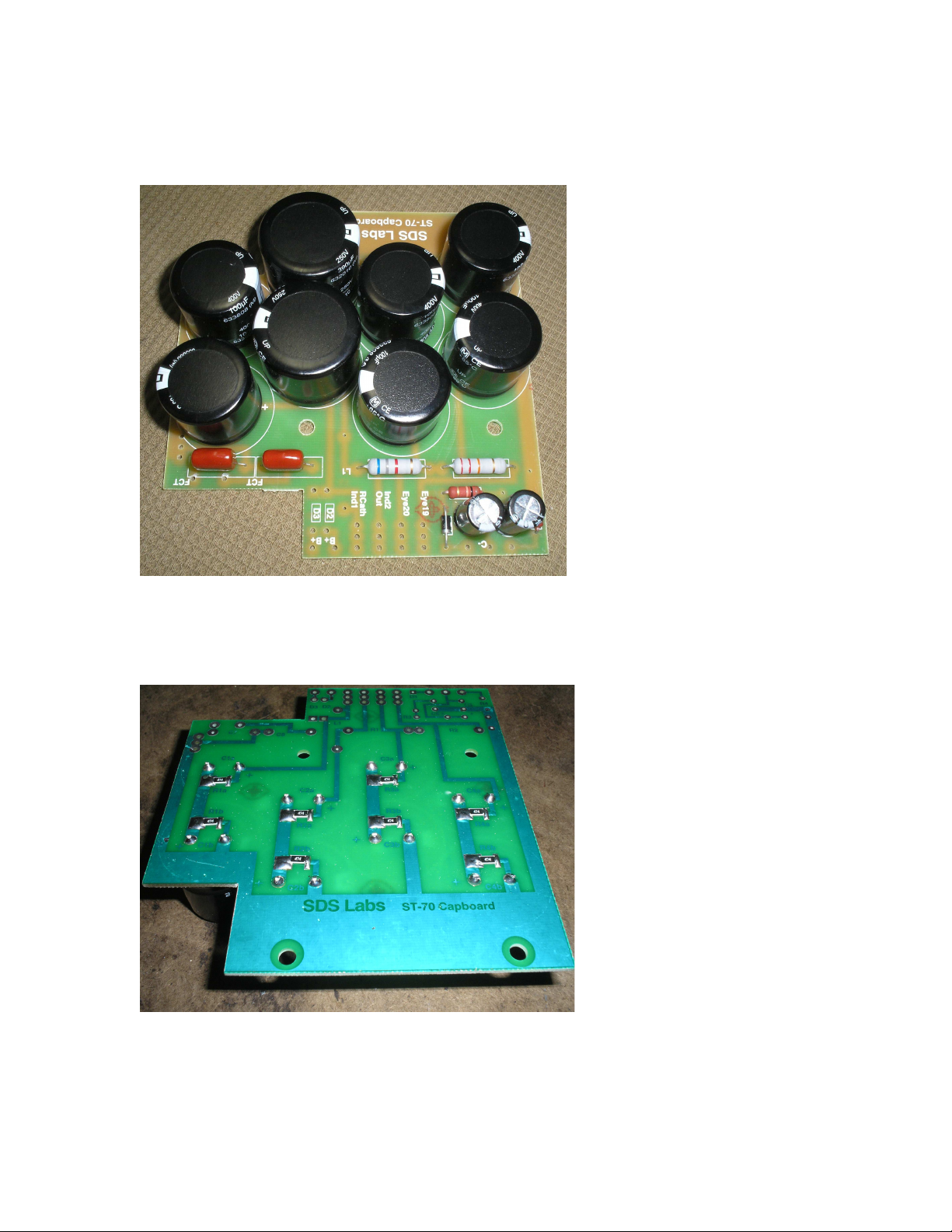
C. Install Bias caps, Heater bypass caps, and bias supply diode
D. Install surface mount resistors onto the bottom of the board
Page 11
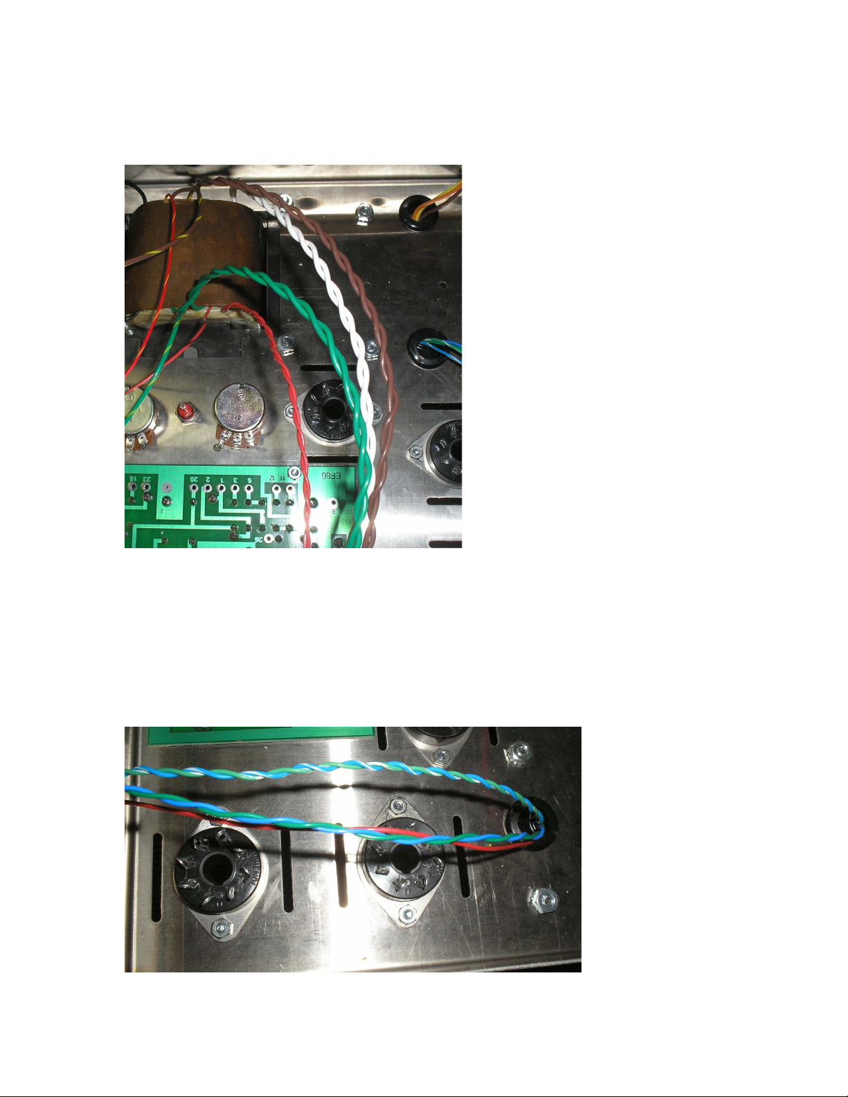
Step 12: Let the wiring begin, lets first twist wires from the power transformer together. Twist the
following wires together: the two green wires, the two brown wires, the two white wires, and the two red
wires.
Step 13: Now twist the wires from the output transformers: twist the blue and green wires together, twist
blue/white and green/white wires together.
Page 12
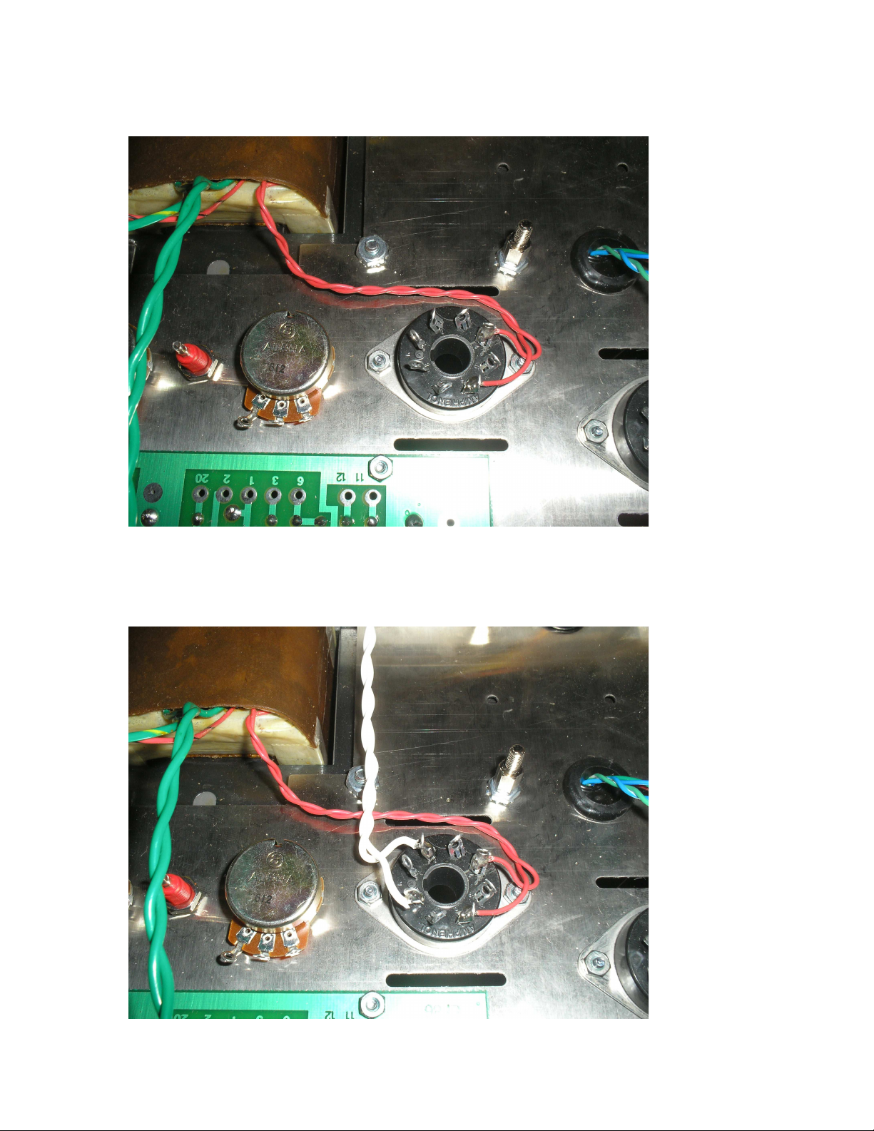
Step 14: Wire the twisted Red leads from the power transformer to pins 4 & 6 of the 5AR4 socket
Step 15: Wire the twisted white leads from power transformer to pins 2 & 8 of the 5AR4 socket
Page 13
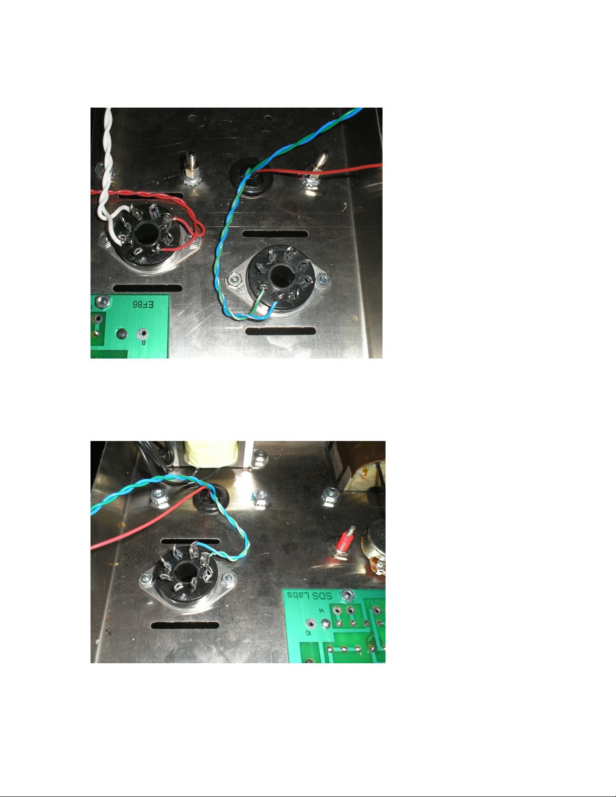
Step 17: Wire the Blue/White & Green/White wires of both output transformers to pins 3 & 4 of the EL34
sockets that are closest to the back of the chassis. Blue/White goes to pin 3 and Green/White to pin 4
Page 14
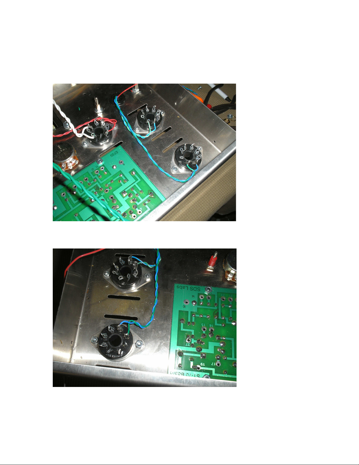
Step 18: Wire the Blue and Green wires from the output transformers to pins 3 & 4 of the other EL34
sockets that are closest to the front of the chassis. The blue wire connects to pin 3 and the Green wire
connects to pin 4.
Page 15
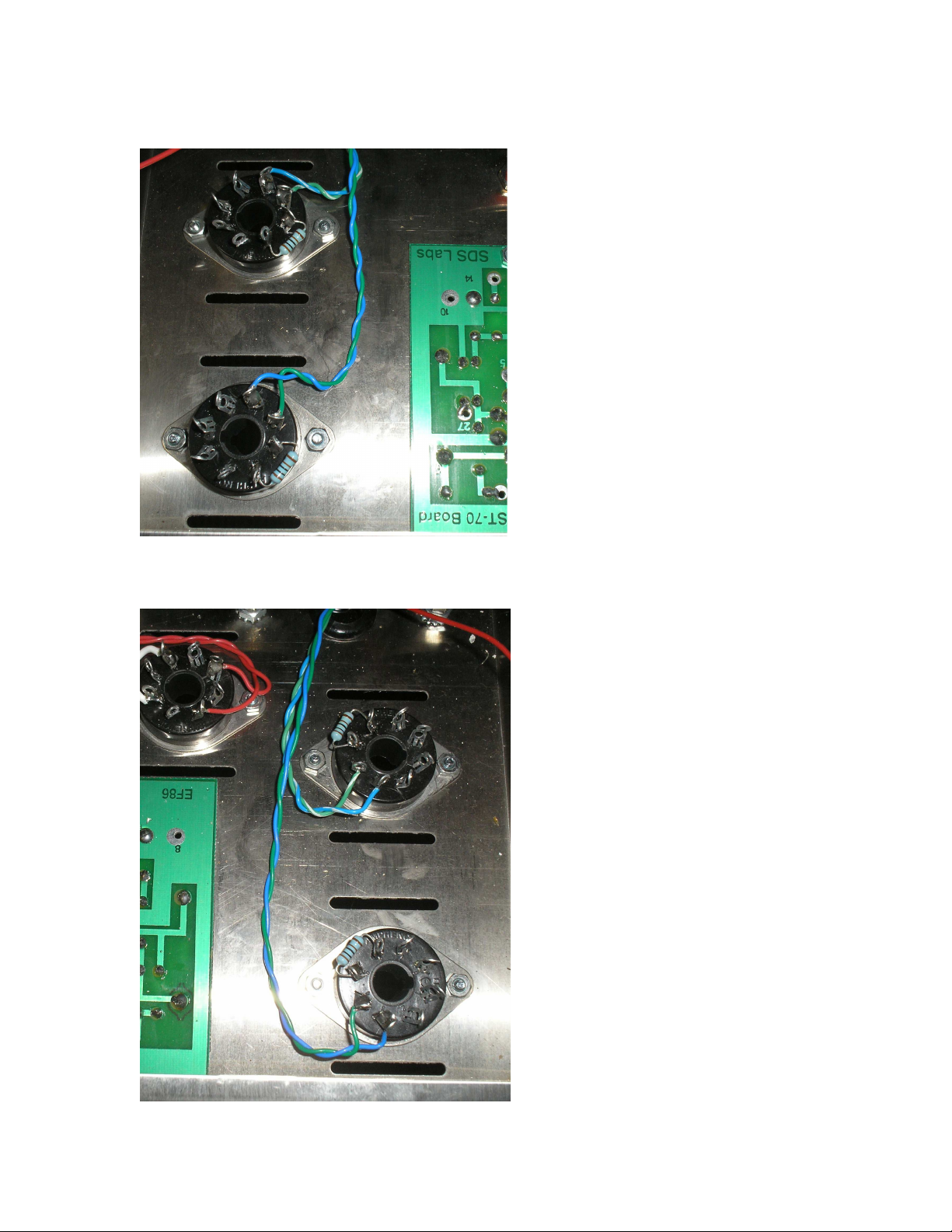
Step 19: Solder 1k grid stopper resistors onto all EL34 sockets. Resistors are installed between pins 5 & 6.
Page 16
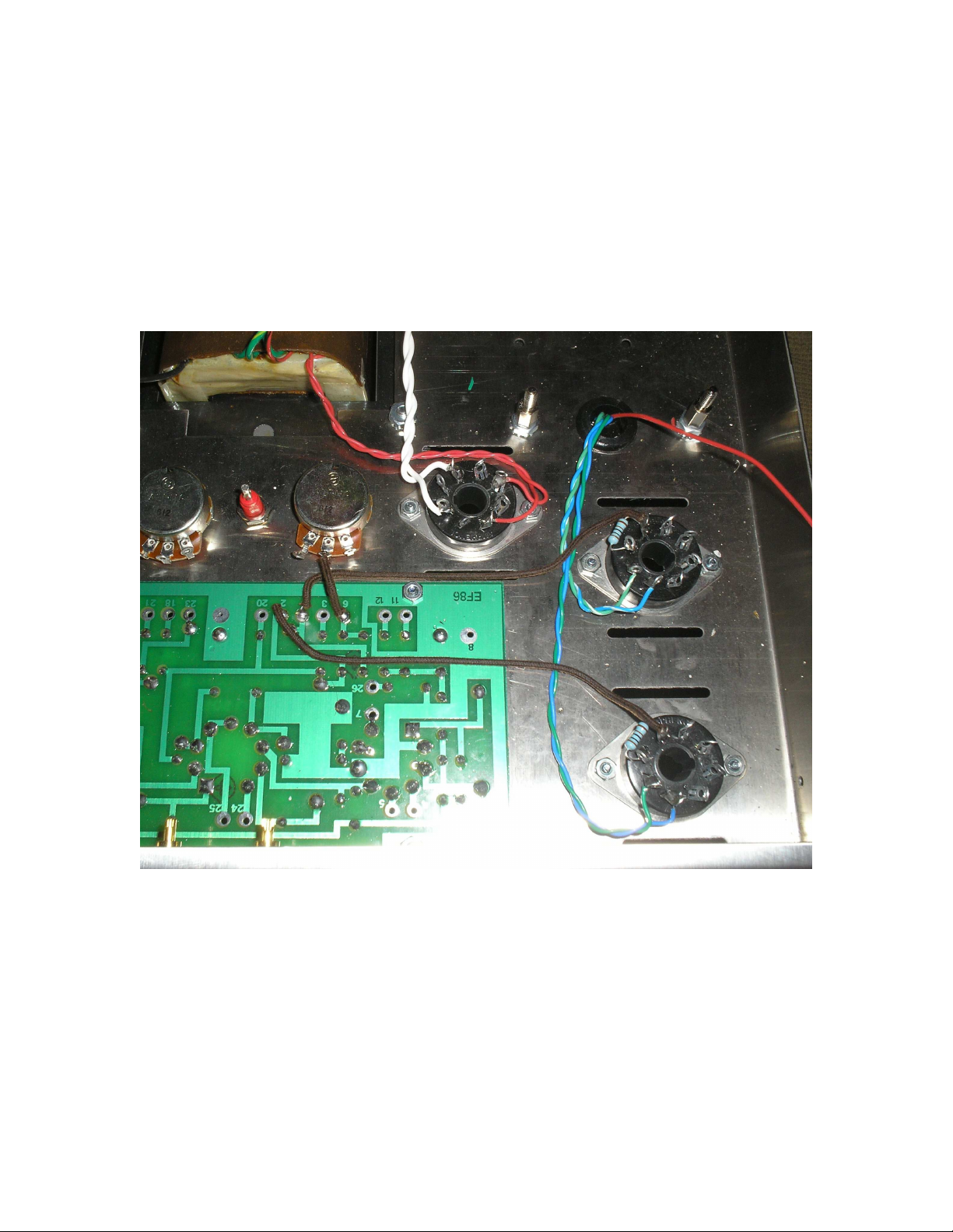
Step 20: Wire Eyelet #6 of the driver board to the center lug of the right bias pot (looking from bottom of
amp). Also wire Eyelet # 2 to pin 6 of The EL34 with the blue/green wires going to it and Eyelet #1 to pin 6
of the EL34 with the Blue/White and Green/White wires going to it.
Page 17
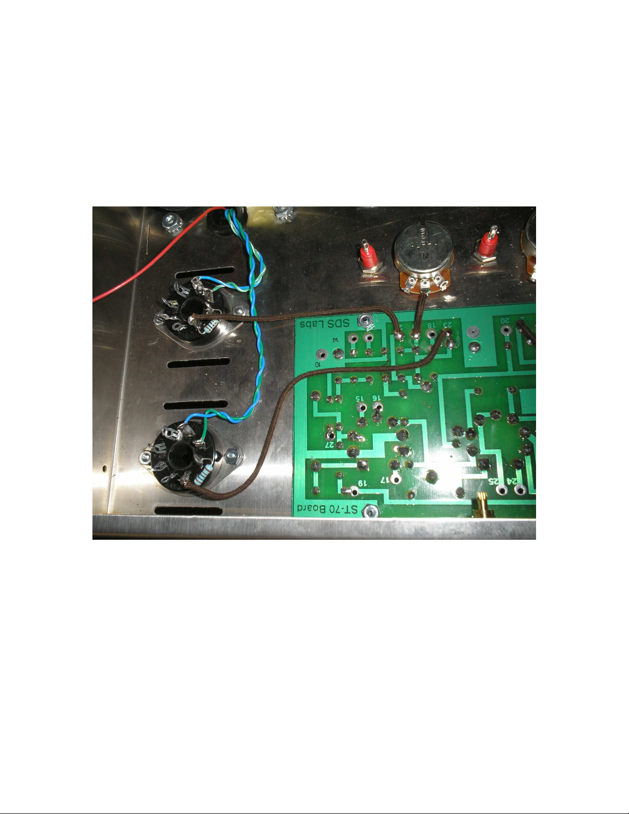
Step #21 Repeat this procedure for the other side of the amplifier, Connect eyelet #21 to center lug of left
bias pot (looking from bottom of amp). Also connect eyelet # 23 to pin 6 of EL34 with the blue/green wires
going to it and eyelet # 22 to pin 6 of the EL34 with the blue/white and green/white wires going to it.
Page 18
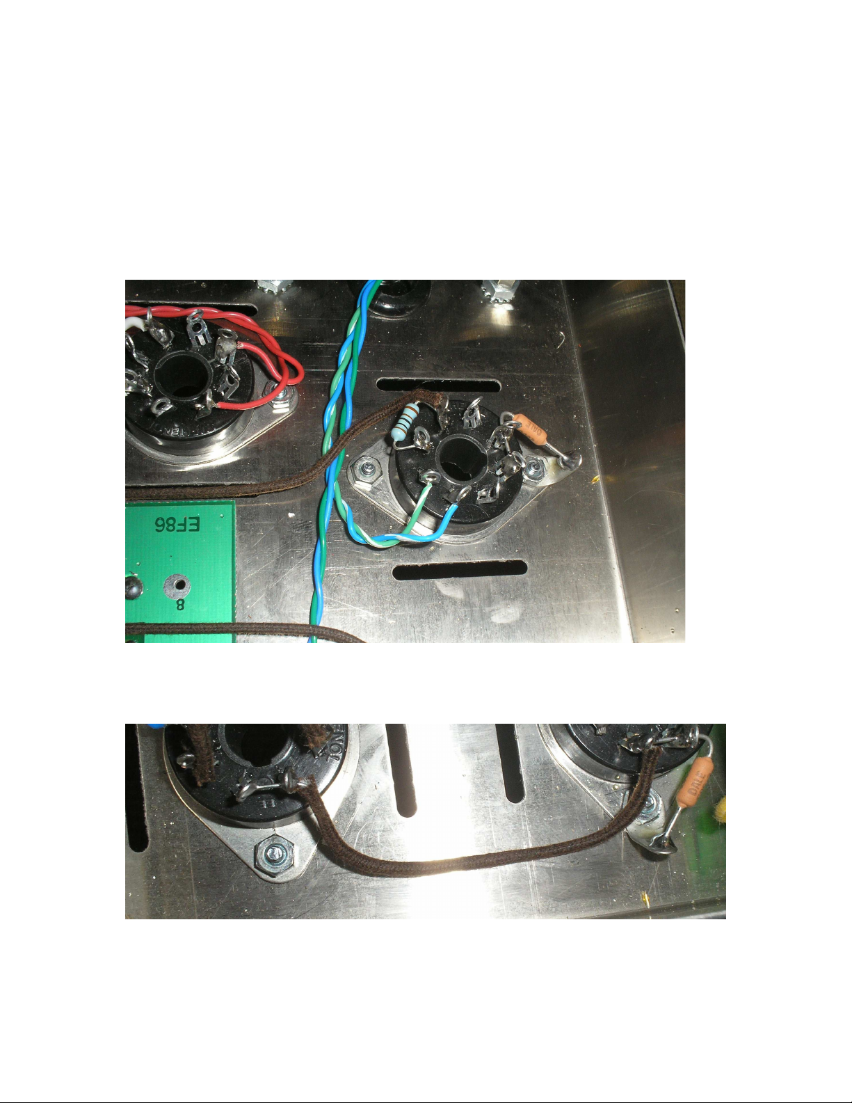
Step 22: install solder lug onto 4-40 bolt/nut that holds on one of the EL34 sockets on each side. Take the
10ohm resistor and connect it to pins 1 & 8 of the EL34 socket to the solder lug. Then take a wire off either
pin 1 or 8 and connect it to pins 1 & 8 of the other EL34 on that side. Do this on both sides of the amplifier.
Page 19

Step 23: Now we will begin wiring the SDS Labs capacitor board into the circuit
A. Connect a wire from pin 8 of the 5AR4 socket to one of the eyelets on the cap board labeled Rcath/Ind1.
Also wire one wire from the C354 choke to the same eyelets.
B. Connect the other wire from the C354 choke to one of the eyelets on the cap board labeled Ind2/Out.
Also wire the red leads from the A470 output transformers to these same eyelets.
C. Connect a wire from the eyelet labeled Eye20, this wire will be connecting to eyelet 20 on the Driver
PCB board so make sure you have enough length.
D. Connect a wire from the eyelet labeled Eye19, this wire will be connecting to eyelet 19 on the Driver
PCB board so make sure you have enough length.
E. Connect the red/black wire from the PA060 power transformer to the eyelet right after the diode on the
board labeled C-.
F. Connect a wire from the right bias pot’s right terminal (looking at amp from bottom) to the next eyelet
after C-
G. Connect a wire from the right bias pots’s left terminal (looking at amp from the bottom) to the last eyelet
on the board .
H. Connect the Green/Yellow wire and Brown/Yellow wire from the PA060 power transformer to the
eyelets marked FCT.
J. Connect a wire to one of the three unlabelled eyelets on the side of the board by the FCT eyelets, this
wire will be going to our main chassis ground point so make sure you leave enough length.
Page 20
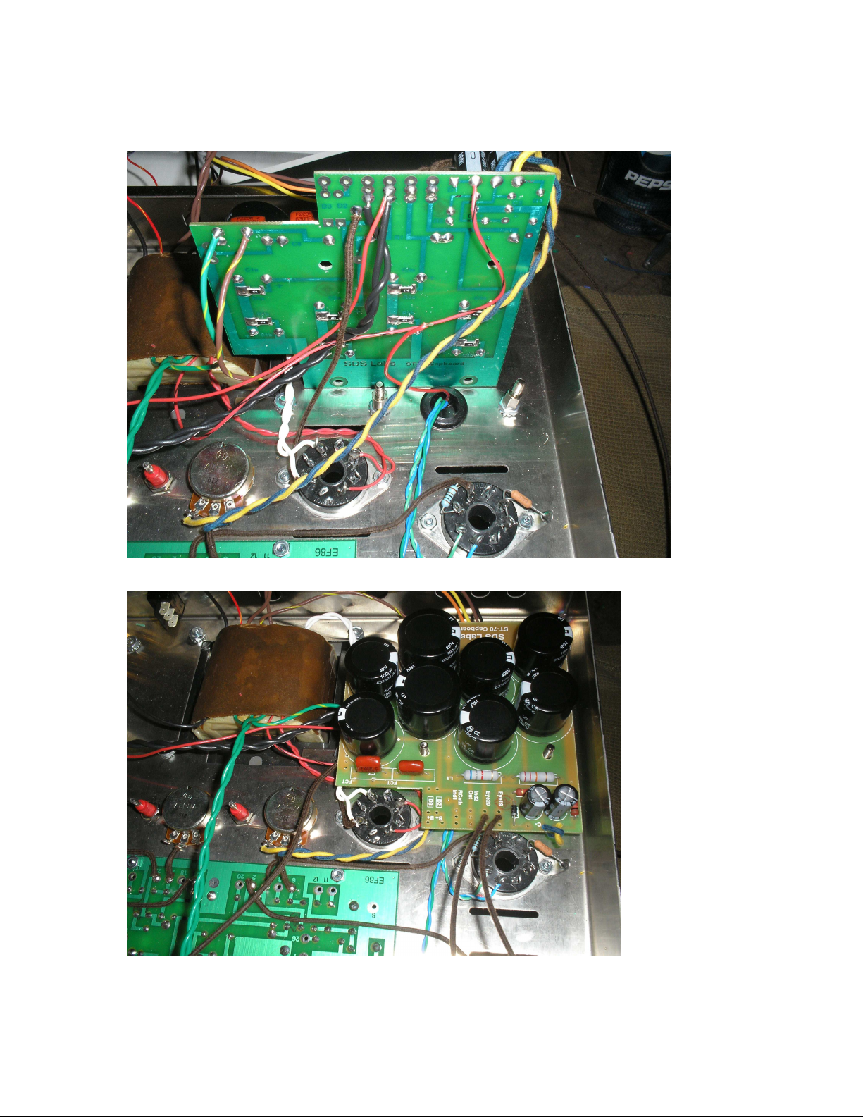
Note: on this picture one of the A470’s red wires is not connected to the board and the main ground wire is
not yet attached.
Page 21
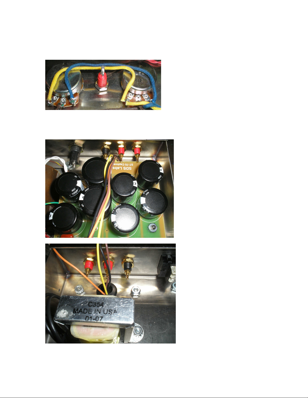
Step 24: Connect a wire from the right terminal of the bias pot to the right terminal of the other bias pot,
Connect a wire from the left terminal of the bias pot to the left terminal of the other bias pot.
Step 25: Install the fuse holder and install binding posts on both sides of the amp
Page 22
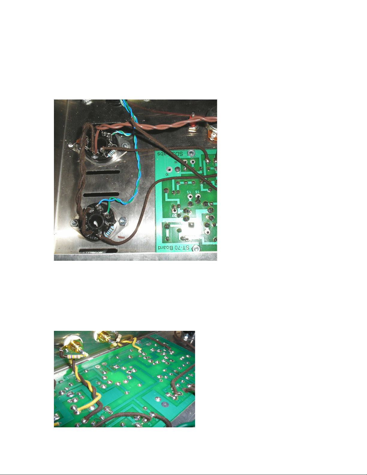
Step 25: Take the twisted green wires and the twisted brown wires from the power transformer and connect
them with a twist tie for cleanliness of wiring. The brown wires will go to pins 2 & 7 of the EL34 socket on
the left side and the Green wires will go to pins 2 & 7 of the EL34’s on the right side.
Step 26: connect two wires from pins 2 & 7 of the EL34 that you just ran the Brown wires to and run them
to pins 2 & 7 of the other EL34 on that side. Connect two wires from pins 2 & 7 of the EL34 that you just
ran the green wires to and connect them to pins 2 & 7 of the other EL34 on that side.
Step 27:
A. Solder a 470k resistor across the center post and lug of the RCA Jacks. Connect a wire from the center
post of the Right RCA jack (looking from bottom of amp) and run to eyelet #7 on the driver board, connect
solder lug of the same RCA jack to eyelet #26.
B. Connect a wire from the center post of the left RCA jack (looking from bottom of amp) and run to eyelet
#17 on the driver board, connect solder lug of the same RCA jack to eyelet #27
Page 23
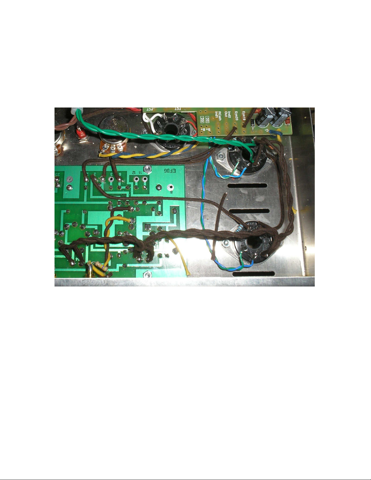
Step 28: Connect two wires from pins 2 & 7 of the EL34’s with the green filament wires going to them
(right side looking from bottom of amp) run these wires to eyelets #4 and #5 on the driver board. Before
soldering to eyelets #4 and #5 also connect a second set of wire into the holes which we will connect to
eyelets #24 and #25 on the driver board
Step 29: Connect two wires from pins 2 & 7 of the EL34’s with the brown filament wires going to them
(Left side looking from bottom of amp) run these wires to eyelets #15 and #16 on the driver board.
Page 24
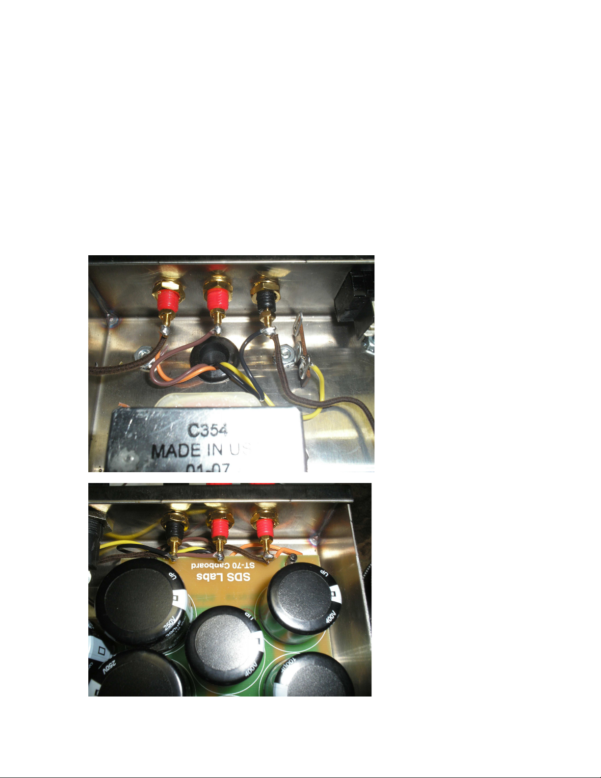
Step 30: Wire the Speaker taps from the A470 output transformers to the binding posts. Black is common
and goes to the black binding posts. Brown is 4ohms and goes to one of the red binding posts. Orange is
8ohms and goes to the other red binding posts, Yellow is the 16ohm tap and is normally not hooked up
unless you are using 16ohm speakers in which case you can omit the wiring of one of the other taps and use
the 16ohm instead. Normally we will either tape up the 16ohm tap and ignore it or you can solder to a
terminal strip to keep out of the way (make sure you don’t solder it to a grounded terminal lug!)
Notes:
A. connect a wire from the 8ohm tap when soldering and connect this wire to eyelet #12 from the right side
speakers jacks (looking from from bottom of amplifier) Connect a wire from the Left side speaker jack’s
(looking from bottom of amplifier) 8ohm tap to eyelet #13.
B. Connect a wire to the black (common) binding posts when soldering and we will run them to the main
chassis ground point later.
Page 25
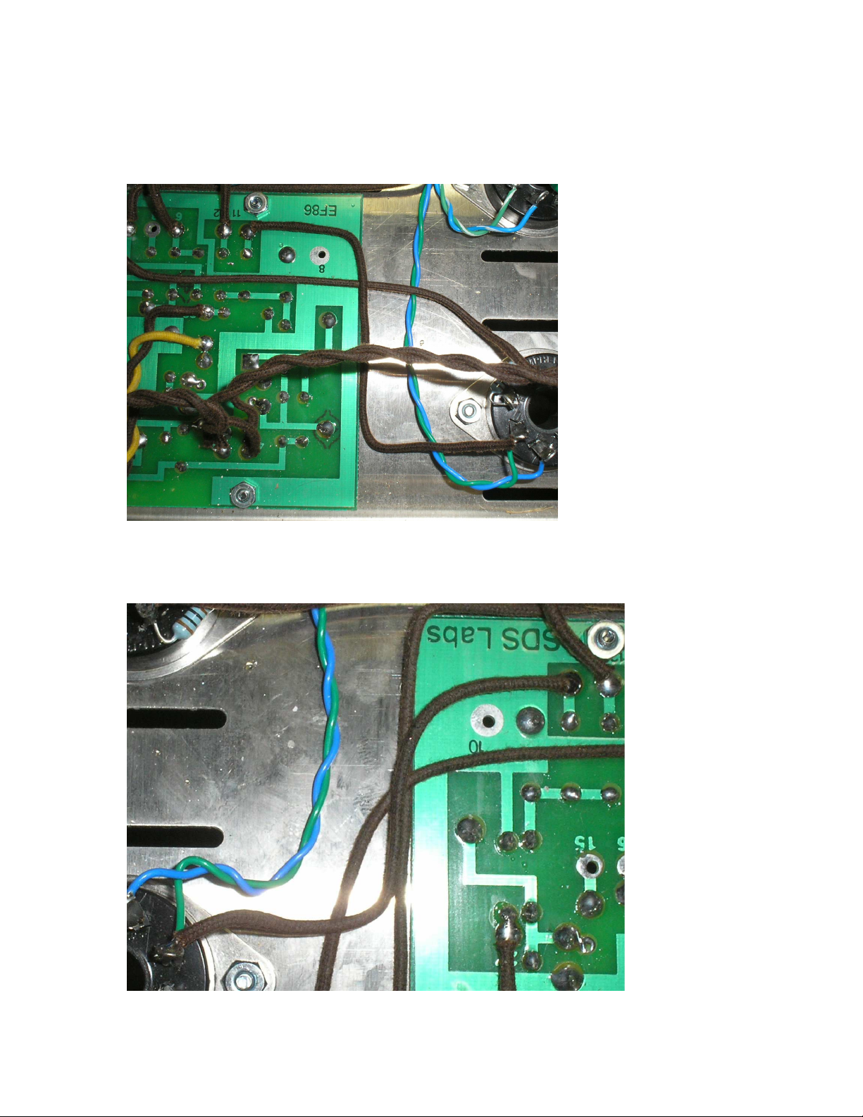
Step 31: Connect a wire from eyelet #11 on driver board to pin 4 of the EL34 on the right side (looking at
amp from bottom) with the blue and green wires going to it. This will be the same pin the green wire is
going to.
Step 32: Connect a wire from eyelet #14 on the driver board to pin 4 of the EL34 on the left side (looking at
amp from bottom) with the blue and green wires going to it. This will be the same pin the green wire is
going to.
Page 26
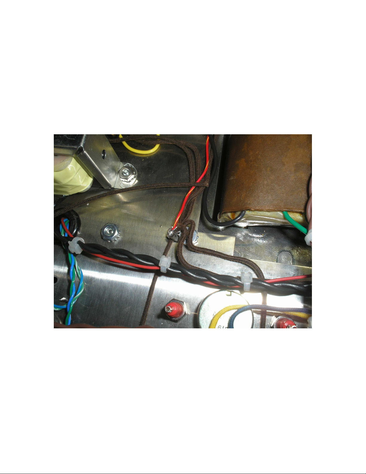
Step 28: Connect a solder lug to one of the mounting bolts for the PA060 power transformer. Connect the
two wires from the black (common) binding posts, the red/yellow wire from the power transformer, the
ground wire from the SDS Labs capacitor board, and a wire from eyelet #9 on the driver board all to the
solder lug terminal. This is the main chassis ground point.
Note: eyelet #9 is not labeled but is located in the top center of the board (looking from bottom of amp with
the front of the amp facing you. You can use either of the two eyelets located here.
Page 27
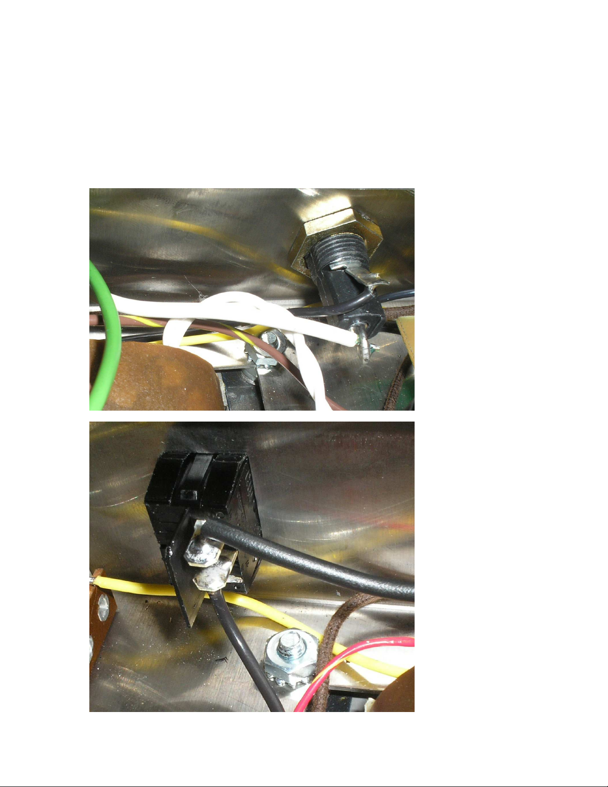
Step 29: Connect the power cord. The white wire of the cord will go to the back lug of the fuse holder, the
black wire of the cord will go to one lug of the power switch, and the green wire should be grounded at any
convenient point on the chassis.
Step 30: Connect one of the black wires from the power transformer to the other lug on the fuse holder,
Connect the other black wire from the power transformer to the other lug of the power switch.
Page 28
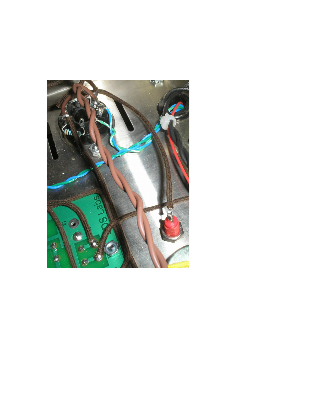
Step 31: Connect a wire from either pin 1 or 8 of the EL34 sockets on the right side to a bias test point,
Connect a wire from either pin 1 or 8 of the EL34 sockets on the left side to the other bias test point.
Step 32: Your are finished with the build, go take a break and come back in a few hours or the next day to
check over all your wiring and do your last final checks before power up the amplifier for the first time.
Page 29
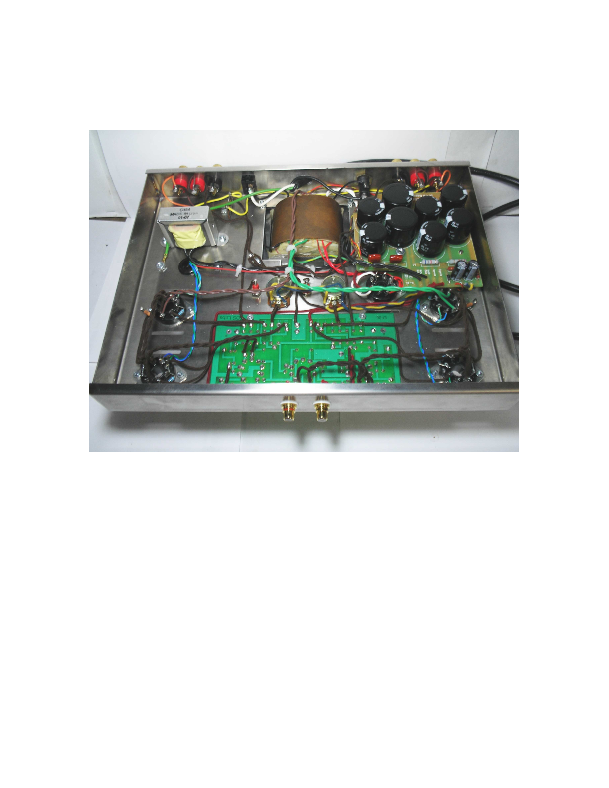
Your finished amplifier should look something like this:
Final Installation Instructions:
A. Install the EL34’s and 5AR4 into the octal sockets on the top of the amplifier
B. Install two EF86’s on the two outside sockets of the driver PCB board
C. Install one 12AU7, 12BH7, or ECC99 into the middle socket of the driver PCB board
D. Install a 2.5A slo-blo fuse into the fuse holder
E. Hook up speakers to the speaker binding posts on the back of the amplifier. Make sure to hookup to the
correct speaker tap
F. Install shorting plugs into the front RCA jacks.
G. Turn bias potentiometers to their middle position
Page 30

Bias Instructions:
Now get out your voltmeter and set it for a low DC volts range, must be at least 2VDC. Connect the black
lead to the chassis at any point and connect the red lead to one of the bias test points.
Switch your meter over to its ohms setting and you should read 10ohms, move the red lead to the other bias
test point and you should read 10ohms here as well. If this is all good go ahead and set the meter back to the
DC volts range.
Now Plug in the amplifier and flip the power switch on, you should see the tubes begin to light up, if not
turn the amplifier off and recheck the wiring of the filaments. After about 20 seconds or so of the tubes
being lit up you should begin to get a reading on your meter. We want to set the bias of each side to 1VDC
on the meter, turning the bias potentiometers clockwise will cause the voltage reading to go up and
counterclockwise will cause it to decrease. Slowly adjust the pots going back and forth between the test
points as changing one pot will affect the other one slightly. Once you have both sides set to 1V or slightly
below you can power the amplifier off.
Remove the RCA shorting plugs from the input jacks and connect your source to the amplifier. Turn the
amplifier back on and listen to the amplifier for any audible problems, hopefully we will hear nothing but
beautiful music. If you have any problems refer to the troubleshooting section in the driver board
instructions.
Page 31

 Loading...