

Trio Motion Coordinator MC216, Motion Coordinator Euro 205, Motion Coordinator MC224, Motion Coordinator MC202, Motion Coordinator MC206 Technical Reference Manual
Page 1

Trio Motion Technology
Motion Coordinator
Technical Reference Manual
Sixth Edition • 2004
Revision 4
Page 2

All goods supplied by Trio are subject to Trio's standard terms and conditions of sale.
This manual applies to systems based on the Motion Coordinator MC202, Euro 205 and MC216 with sys-
tem software version 1.52, or higher. Or MC206 and MC224 with system software version 1.62, or
higher.
The material in this manual is subject to change without notice. Despite every effort, in a manual of
this scope errors and omissions may occur. Th er efore Trio cannot be held responsibl e for any malfunctions or loss of data as a result.
Revision 6.4 April 2004
Copyright (C) 2000-2004 Trio Motion Technology Ltd.
All Rights Reserved
UK
Trio Motion Technology Ltd.
Shannon Way
Tewkesbury
GL20 8ND
United Kingdom
Phone: +44 (0)1684 292333
Fax: +44 (0)1684 297929
USA
Trio Motion Technology LLC.
1000 Gamma Drive, Suite 206
Pittsburgh
PA 15238,
USA
Phone: +1 412 968 9744
Fax: +1 412 968 9746
Page 3
SAFETY WARNING
!
During the installation or use of a control system, users of Trio products must
ensure there is no possibility of injury to any person, or damage to
machinery.
Control systems, especially during installation, can malfunction or behave
unexpectedly. Bearing t hi s i n m in d , us er s m us t ensure that ev en in the e ve nt
of a malfunction or une xpected behaviour the safety of an operator or
programmer is never compromised.
!
Page 4

Page 5

Motion Coordinator Technical Refe ren ce Ma n ual
INTRODUCTION . . . . . . . . . . . . . . . . . . . . . . . . . . . 1- 1
Setup and Programming . . . . . . . . . . . . . . . . . . . . . . . . . . . . . 1-4
Products . . . . . . . . . . . . . . . . . . . . . . . . . . . . . . . . . . . . . . . 1-5
System Building . . . . . . . . . . . . . . . . . . . . . . . . . . . . . . . . . . 1-11
System Exam ples . . . . . . . . . . . . . . . . . . . . . . . . . . . . . . . 1-12
Features and Typic al Applications . . . . . . . . . . . . . . . . . . . . 1-15
The Trio Mot i o n Technology Website . . . . . . . . . . . . . . . . . . 1-16
HARDWARE OVERVIEW . . . . . . . . . . . . . . . . . . . . . . . 2-1
Motion Coordin ator MC202 . . . . . . . . . . . . . . . . . . . . . . . . . . . 2-3
Connections to the MC202 . . . . . . . . . . . . . . . . . . . . . . . . . 2-4
Seria l P ort Connections . . . . . . . . . . . . . . . . . . . . . . . . . . . 2-7
MC202 - Feature Summary . . . . . . . . . . . . . . . . . . . . . . . . . 2-8
Motion Coordin ator Euro205(X) . . . . . . . . . . . . . . . . . . . . . . . . 2-10
Axis C o nfiguration . . . . . . . . . . . . . . . . . . . . . . . . . . . . . . 2 -11
Connections to the E uro 205(X) . . . . . . . . . . . . . . . . . . . . . . 2-12
Euro 205(X) Backpl ane Con necto r . . . . . . . . . . . . . . . . . . . . 2-13
Euro205 - Feature Summary . . . . . . . . . . . . . . . . . . . . . . . . 2-19
Euro205X - Feature Summary . . . . . . . . . . . . . . . . . . . . . . . 2-20
Motion Coordin ator MC206 . . . . . . . . . . . . . . . . . . . . . . . . . . . 2-22
Connections to the MC206 . . . . . . . . . . . . . . . . . . . . . . . . . 2-25
Amplifier Enable (Watchdog) Relay Output . . . . . . . . . . . . . . 2-28
Reference En coder Input . . . . . . . . . . . . . . . . . . . . . . . . . . 2-29
Universal Serial Bu s . . . . . . . . . . . . . . . . . . . . . . . . . . . . . 2-29
MC206 - Stepper Outp uts / Encoder Inputs . . . . . . . . . . . . . . 2-30
MC206 - Feature Summary . . . . . . . . . . . . . . . . . . . . . . . . . 2-31
Motion Coordinator MC216 . . . . . . . . . . . . . . . . . . . . . . . . . . . 2-33
Connections to the MC216 . . . . . . . . . . . . . . . . . . . . . . . . . 2-35
MC216 - Feature Summary . . . . . . . . . . . . . . . . . . . . . . . . . 2-40
Motion Coordinator MC224 . . . . . . . . . . . . . . . . . . . . . . . . . . . 2-41
Connections to the MC224 . . . . . . . . . . . . . . . . . . . . . . . . . 2-43
MC224 - Feature Summary . . . . . . . . . . . . . . . . . . . . . . . . . 2-48
CONTENTS
INSTALLATION . . . . . . . . . . . . . . . . . . . . . . . . . . . . 3-1
Motion Coordin ator MC202 . . . . . . . . . . . . . . . . . . . . . . . . . . . 3-3
Motion Coordinato r Euro 205 . . . . . . . . . . . . . . . . . . . . . . . 3-5
Motion Coordin ator MC216 . . . . . . . . . . . . . . . . . . . . . . . . . . . 3-6
Motion Coordin ator MC206 . . . . . . . . . . . . . . . . . . . . . . . . . . . 3-8
i
Page 6

Trio Motion Technol og y
EMC Considerations . . . . . . . . . . . . . . . . . . . . . . . . . . . . . . . . .3-9
DAUGHTER BOARDS . . . . . . . . . . . . . . . . . . . . . . . . .4- 1
Fitti ng and Handling Dau ghter Bo ards . . . . . . . . . . . . . . . . . . . . .4-4
Fitting Daughter Boards to the Euro205 . . . . . . . . . . . . . . . . . . . .4-7
Fitti ng Daughter Boards to the MC 206 . . . . . . . . . . . . . . . . . . . . .4-9
Servo Encoder Daug hter Boa rd . . . . . . . . . . . . . . . . . . . . . . . . .4 -11
Servo Resolver Daughter Bo ard . . . . . . . . . . . . . . . . . . . . . . . . .4 -14
Reference Encoder Daughter Board . . . . . . . . . . . . . . . . . . . . . .4-16
Stepper Daughter Bo ard . . . . . . . . . . . . . . . . . . . . . . . . . . . . . .4-18
Stepper Enc o der Daughter . . . . . . . . . . . . . . . . . . . . . . . . . . . .4 -20
Hardware PSWITCH Daughter Board . . . . . . . . . . . . . . . . . . . . . .4-23
Analog Output Daughter Board . . . . . . . . . . . . . . . . . . . . . . . . .4-25
SSI Servo Enc o der Daughter B oard . . . . . . . . . . . . . . . . . . . . . . .4-26
Differential Stepper Daughter Board . . . . . . . . . . . . . . . . . . . . . .4-29
CAN Daughter Board . . . . . . . . . . . . . . . . . . . . . . . . . . . . . . . .4-31
SERCOS Daug hter B o ard . . . . . . . . . . . . . . . . . . . . . . . . . . . . . .4-32
SLM Daughter Board . . . . . . . . . . . . . . . . . . . . . . . . . . . . . . . .4-33
USB Daughter Board . . . . . . . . . . . . . . . . . . . . . . . . . . . . . . . .4-35
Ethernet Daughter B oard . . . . . . . . . . . . . . . . . . . . . . . . . . . . .4-36
Profibus Daughte r B oard . . . . . . . . . . . . . . . . . . . . . . . . . . . . .4-37
Installation Requirements to Ensure Conformance . . . . . . . . . .3-11
Motion Coordinator MC202 . . . . . . . . . . . . . . . . . . . . . . . . .3-11
Motion Coordinator Euro 205 . . . . . . . . . . . . . . . . . . . . . . . . 3-11
Motion Coordinator MC206 . . . . . . . . . . . . . . . . . . . . . . . . .3-12
Motion Coordinator MC216 . . . . . . . . . . . . . . . . . . . . . . . . .3-13
MC216 + Axis Ex pander Slot Sequence . . . . . . . . . . . . . . . . . .4-6
EXPANSION MODULE S . . . . . . . . . . . . . . . . . . . . . . . . 5-1
Input /Outp ut Modu les . . . . . . . . . . . . . . . . . . . . . . . . . . . . . . .5 -3
CAN 16-I/O Module (P315 ) . . . . . . . . . . . . . . . . . . . . . . . . . .5 -3
CAN Analog Inputs Module (P325) . . . . . . . . . . . . . . . . . . . . . . . .5-11
Oper ator Int erfaces . . . . . . . . . . . . . . . . . . . . . . . . . . . . . . . . .5 -15
Membrane Keypad (P503) . . . . . . . . . . . . . . . . . . . . . . . . . .5-16
Mini-Membrane Key pad (P5 02) . . . . . . . . . . . . . . . . . . . . . . .5-19
Programming the Me mbrane Keypad . . . . . . . . . . . . . . . . . . .5-20
Keypad KEY ON - KEY OFF Mode . . . . . . . . . . . . . . . . . . . . . .5-24
FO-VFKB Fib re Optic Keypad/Di splay Interf ace . . . . . . . . . . . . . . .5 -26
FO-VFKB Keypad In terface . . . . . . . . . . . . . . . . . . . . . . . . . .5-26
Communications Adaptors . . . . . . . . . . . . . . . . . . . . . . . . . . . .5-28
Serial to RS485 Adapter: (P348) . . . . . . . . . . . . . . . . . . . . . .5-28
P349 - Serial to RS485 adapter to an MC202: . . . . . . . . . . . . . .5-30
ii
Page 7

Motion Coordinator Technical Refe ren ce Ma n ual
P435 - S erial to Fibre-Opt ic Adapt er . . . . . . . . . . . . . . . . . . 5-31
SYSTEM SETUP AND DIAGNOSTICS . . . . . . . . . . . . . . . . . 6- 1
Preliminary Conc epts: . . . . . . . . . . . . . . . . . . . . . . . . . . . . . . 6-3
System Setup . . . . . . . . . . . . . . . . . . . . . . . . . . . . . . . . . 6-3
Preliminary checks . . . . . . . . . . . . . . . . . . . . . . . . . . . . . . 6-4
Checking Communications and System Configuration . . . . . . . 6-4
Input/Output Connections: . . . . . . . . . . . . . . . . . . . . . . . . 6-6
Setting Ser v o Gains . . . . . . . . . . . . . . . . . . . . . . . . . . . . . . . . 6-8
Proportional Gain . . . . . . . . . . . . . . . . . . . . . . . . . . . . . . . 6-10
Integral gain . . . . . . . . . . . . . . . . . . . . . . . . . . . . . . . . . . 6-10
Deriv ative gain . . . . . . . . . . . . . . . . . . . . . . . . . . . . . . . . 6-1 0
Output Velo ci ty Gain . . . . . . . . . . . . . . . . . . . . . . . . . . . . 6-11
Veloc i ty Feed Forwa r d Gain . . . . . . . . . . . . . . . . . . . . . . . . 6-11
Diagnostic Checklists . . . . . . . . . . . . . . . . . . . . . . . . . . . . . . . 6 -13
PROGRAMMING . . . . . . . . . . . . . . . . . . . . . . . . . . . 7- 1
What is a prog ram? . . . . . . . . . . . . . . . . . . . . . . . . . . . . . . 7-3
Sequence . . . . . . . . . . . . . . . . . . . . . . . . . . . . . . . . . . . . 7-4
Selection . . . . . . . . . . . . . . . . . . . . . . . . . . . . . . . . . . . . 7-5
Iteration . . . . . . . . . . . . . . . . . . . . . . . . . . . . . . . . . . . . . 7-5
Controller Functions . . . . . . . . . . . . . . . . . . . . . . . . . . . . . 7-7
. . . . . . . . . . . . . . . . . . . . . . . . . . . . . . . . . . . . . . . . . . 7-7
Ident i fiers . . . . . . . . . . . . . . . . . . . . . . . . . . . . . . . . . . . . 7 -8
Expressions . . . . . . . . . . . . . . . . . . . . . . . . . . . . . . . . . . . 7-9
Parameters . . . . . . . . . . . . . . . . . . . . . . . . . . . . . . . . . . . 7-11
Command Line Interface . . . . . . . . . . . . . . . . . . . . . . . . . . 7-15
TRIO BASIC
OMMANDS . . . . . . . . . . . . . . . . . . . . . . . . . . . . . 8-1
C
Motion and A xis Commands . . . . . . . . . . . . . . . . . . . . . . . . . . . 8-11
Input / Output Commands . . . . . . . . . . . . . . . . . . . . . . . . . . . 8-4 5
Program Loops and Structures . . . . . . . . . . . . . . . . . . . . . . . . . 8-65
Syst em Parameters and Co mmands . . . . . . . . . . . . . . . . . . . . . . 8-78
Process Parameters and Commands . . . . . . . . . . . . . . . . . . . . . 8-129
Mathematical Operations and Commands . . . . . . . . . . . . . . . . . . 8-133
Cons tants . . . . . . . . . . . . . . . . . . . . . . . . . . . . . . . . . . . . . . 8-150
Axis Parameters . . . . . . . . . . . . . . . . . . . . . . . . . . . . . . . . . . 8 -152
PROGRAMMING EXAMPLES . . . . . . . . . . . . . . . . . . . . . 9- 1
Example Programs . . . . . . . . . . . . . . . . . . . . . . . . . . . . . . . . . 9-3
iii
Page 8

Trio Motion Technol og y
SUPPORT SOFTWARE . . . . . . . . . . . . . . . . . . . . . . . .10 -1
Motion Perfect 2 . . . . . . . . . . . . . . . . . . . . . . . . . . . . . . . . . .10-3
Connecting Motion Perfect to a control ler . . . . . . . . . . . . . . . . . .1 0-6
Motion Perfect 2 Projects . . . . . . . . . . . . . . . . . . . . . . . . . . . . .10-7
The Motion Perfect Desktop . . . . . . . . . . . . . . . . . . . . . . . . . . .10-11
Motion Perfect Tools . . . . . . . . . . . . . . . . . . . . . . . . . . . . . . . .10-21
Linking to External Tools . . . . . . . . . . . . . . . . . . . . . . . . . . . . .10-45
Control Panel . . . . . . . . . . . . . . . . . . . . . . . . . . . . . . . . . . . . .10-47
Creating and Running a program . . . . . . . . . . . . . . . . . . . . . . . .10-52
Program Debugger . . . . . . . . . . . . . . . . . . . . . . . . . . . . . . . . .10-58
Running Programs . . . . . . . . . . . . . . . . . . . . . . . . . . . . . . . . . .10-61
Making programs run automatically . . . . . . . . . . . . . . . . . . . . . .10-62
Storing Programs in the Flash EPROM . . . . . . . . . . . . . . . . . . . . .10-63
Configuring The Motion Perfect 2 De sktop . . . . . . . . . . . . . . . . . .10-64
Running Motion Perfect 2 Without a Controller . . . . . . . . . . . . . .10-69
System Requirements: . . . . . . . . . . . . . . . . . . . . . . . . . . . . 10-4
New Features for Motion Perfect 1 Users . . . . . . . . . . . . . . . .1 0-5
The Project Check Window . . . . . . . . . . . . . . . . . . . . . . . . .10-7
Project Chec k Options . . . . . . . . . . . . . . . . . . . . . . . . . . . .10-8
Main Menu . . . . . . . . . . . . . . . . . . . . . . . . . . . . . . . . . . . .10-12
Controller Menu . . . . . . . . . . . . . . . . . . . . . . . . . . . . . . . .10-13
Controller Configuration . . . . . . . . . . . . . . . . . . . . . . . . . . .10-14
Feature Enable . . . . . . . . . . . . . . . . . . . . . . . . . . . . . . . . .10-15
Loading New System Software . . . . . . . . . . . . . . . . . . . . . . .10-17
Flashstick support . . . . . . . . . . . . . . . . . . . . . . . . . . . . . . .10-19
Lock / Unlock . . . . . . . . . . . . . . . . . . . . . . . . . . . . . . . . . .10-20
Terminal . . . . . . . . . . . . . . . . . . . . . . . . . . . . . . . . . . . . .10-22
Axis Parameters . . . . . . . . . . . . . . . . . . . . . . . . . . . . . . . .10-23
Oscilloscope . . . . . . . . . . . . . . . . . . . . . . . . . . . . . . . . . . .10-26
Keypad Emulation . . . . . . . . . . . . . . . . . . . . . . . . . . . . . . .10-35
Table / VR Editor . . . . . . . . . . . . . . . . . . . . . . . . . . . . . . . .10-37
Jog Axes . . . . . . . . . . . . . . . . . . . . . . . . . . . . . . . . . . . . .10-38
Digital IO Status . . . . . . . . . . . . . . . . . . . . . . . . . . . . . . . .10-42
Analogue Input View er . . . . . . . . . . . . . . . . . . . . . . . . . . . .10-44
The Motion Perfect Edit o r . . . . . . . . . . . . . . . . . . . . . . . . . .10-53
Editor Menus . . . . . . . . . . . . . . . . . . . . . . . . . . . . . . . . . . .10-56
Set Powerup Mode . . . . . . . . . . . . . . . . . . . . . . . . . . . . . . .10-62
Communications . . . . . . . . . . . . . . . . . . . . . . . . . . . . . . . .10-64
Changing Comms Port Paramete rs . . . . . . . . . . . . . . . . . . . . .10-65
Editor Options . . . . . . . . . . . . . . . . . . . . . . . . . . . . . . . . . .10-67
General Options . . . . . . . . . . . . . . . . . . . . . . . . . . . . . . . .10-67
Savin g the Desktop Layout . . . . . . . . . . . . . . . . . . . . . . . . . .10-68
iv
Page 9

Trio Motion Technol og y
CAD2Motio n . . . . . . . . . . . . . . . . . . . . . . . . . . . . . . . . . . . . . .10-72
DocMaker . . . . . . . . . . . . . . . . . . . . . . . . . . . . . . . . . . . . . . .10-73
Project Autoloader . . . . . . . . . . . . . . . . . . . . . . . . . . . . . . . . .10-74
FIBRE-OPTIC NETWORK . . . . . . . . . . . . . . . . . . . . . . .11-1
General Description . . . . . . . . . . . . . . . . . . . . . . . . . . . . . . . .11-3
Network Programming . . . . . . . . . . . . . . . . . . . . . . . . . . . . . . .11-6
Network Specification . . . . . . . . . . . . . . . . . . . . . . . . . . . . . . .11-12
USING THE TRIO
ACTIV EX CONTROL . . . . . . . . . . . . . . . . . . . . . . . . .12 -1
Connection Commands . . . . . . . . . . . . . . . . . . . . . . . . . . . . . . .12-4
Properties . . . . . . . . . . . . . . . . . . . . . . . . . . . . . . . . . . . . . . .12-7
Motion Commands . . . . . . . . . . . . . . . . . . . . . . . . . . . . . . . . . .12-9
Process Control Co mmand s . . . . . . . . . . . . . . . . . . . . . . . . . . . .12-18
Variable Commands . . . . . . . . . . . . . . . . . . . . . . . . . . . . . . . . . 12-19
Input / Output Commands . . . . . . . . . . . . . . . . . . . . . . . . . . . .12-22
General commands . . . . . . . . . . . . . . . . . . . . . . . . . . . . . . . . .12-28
Events . . . . . . . . . . . . . . . . . . . . . . . . . . . . . . . . . . . . . . . . .12-30
MC Simulation . . . . . . . . . . . . . . . . . . . . . . . . . . . . . . . . . .10-69
Files . . . . . . . . . . . . . . . . . . . . . . . . . . . . . . . . . . . . . . . .10-75
. . . . . . . . . . . . . . . . . . . . . . . . . . . . . . . . . . . . . . . . . . .10-75
Running the program . . . . . . . . . . . . . . . . . . . . . . . . . . . . .10-76
Script Commands . . . . . . . . . . . . . . . . . . . . . . . . . . . . . . . .10-77
Script File . . . . . . . . . . . . . . . . . . . . . . . . . . . . . . . . . . . .10-82
Connection o f Network . . . . . . . . . . . . . . . . . . . . . . . . . . . .11-4
Examples of network programming . . . . . . . . . . . . . . . . . . . .11-8
Introduction . . . . . . . . . . . . . . . . . . . . . . . . . . . . . . . . . . .12-3
Requirements . . . . . . . . . . . . . . . . . . . . . . . . . . . . . . . . . .12-3
Insta llation of the A ctiveX Component . . . . . . . . . . . . . . . . . .12-3
Using the Component . . . . . . . . . . . . . . . . . . . . . . . . . . . . .12-3
TrioPC status . . . . . . . . . . . . . . . . . . . . . . . . . . . . . . . . . .12-31
COMMUNICATIONS PROTOCOLS . . . . . . . . . . . . . . . . . . . 13-1
MODBUS RTU . . . . . . . . . . . . . . . . . . . . . . . . . . . . . . . . . . . . .13-3
Introduction . . . . . . . . . . . . . . . . . . . . . . . . . . . . . . . . . . .13-3
Initialisation and Set-up . . . . . . . . . . . . . . . . . . . . . . . . . . .13-3
Modbus Technical Reference . . . . . . . . . . . . . . . . . . . . . . . .13-4
Glossary . . . . . . . . . . . . . . . . . . . . . . . . . . . . . . . . . . . . . .13-7
Profibus . . . . . . . . . . . . . . . . . . . . . . . . . . . . . . . . . . . . . . . .13-8
Installation and Set-up . . . . . . . . . . . . . . . . . . . . . . . . . . . .1 3-8
v
Page 10

Trio Motion Technol og y
DeviceNet . . . . . . . . . . . . . . . . . . . . . . . . . . . . . . . . . . . . . . .13-13
Ethernet . . . . . . . . . . . . . . . . . . . . . . . . . . . . . . . . . . . . . . . .13-26
REFERENCE . . . . . . . . . . . . . . . . . . . . . . . . . . . . . . 1-1
ATYPE . . . . . . . . . . . . . . . . . . . . . . . . . . . . . . . . . . . . . . . . . .1-3
AXIS STATUS / ERRORMASK . . . . . . . . . . . . . . . . . . . . . . . . . . . .1-4
CONTROL . . . . . . . . . . . . . . . . . . . . . . . . . . . . . . . . . . . . . . .1-5
Communicat i ons Ports . . . . . . . . . . . . . . . . . . . . . . . . . . . . . . . 1-5
Communicat i ons Er rors . . . . . . . . . . . . . . . . . . . . . . . . . . . . . .1-6
MTYP E . . . . . . . . . . . . . . . . . . . . . . . . . . . . . . . . . . . . . . . . .1-7
NETSTAT . . . . . . . . . . . . . . . . . . . . . . . . . . . . . . . . . . . . . . . .1-7
Data Formats and F loati ng-Point Ope r ation s . . . . . . . . . . . . . . . .1-8
Product Codes . . . . . . . . . . . . . . . . . . . . . . . . . . . . . . . . . . . .1-9
Installation and Set-up . . . . . . . . . . . . . . . . . . . . . . . . . . . .1 3-13
Devic eNet Informat i on . . . . . . . . . . . . . . . . . . . . . . . . . . . .13-13
Connecti on Types Implemented . . . . . . . . . . . . . . . . . . . . . .13-14
DeviceNet Objects Implemented . . . . . . . . . . . . . . . . . . . . . 13-14
MC Object . . . . . . . . . . . . . . . . . . . . . . . . . . . . . . . . . . . .13-20
Devic eNet Status LEDs . . . . . . . . . . . . . . . . . . . . . . . . . . . .13-25
Default IP Address . . . . . . . . . . . . . . . . . . . . . . . . . . . . . . .13-26
The Subnet Mask . . . . . . . . . . . . . . . . . . . . . . . . . . . . . . . .13-27
Connecti ng to the Trio Ethernet Daughter Board . . . . . . . . . . .13-28
Single-Prec i sion Floating Point F ormat . . . . . . . . . . . . . . . . . . 1-8
vi
Page 11

CHAPTER
CHAPTER 0INTRODUCTION
Page 12

Page 13
Motion Coordinator Technical Reference Manual
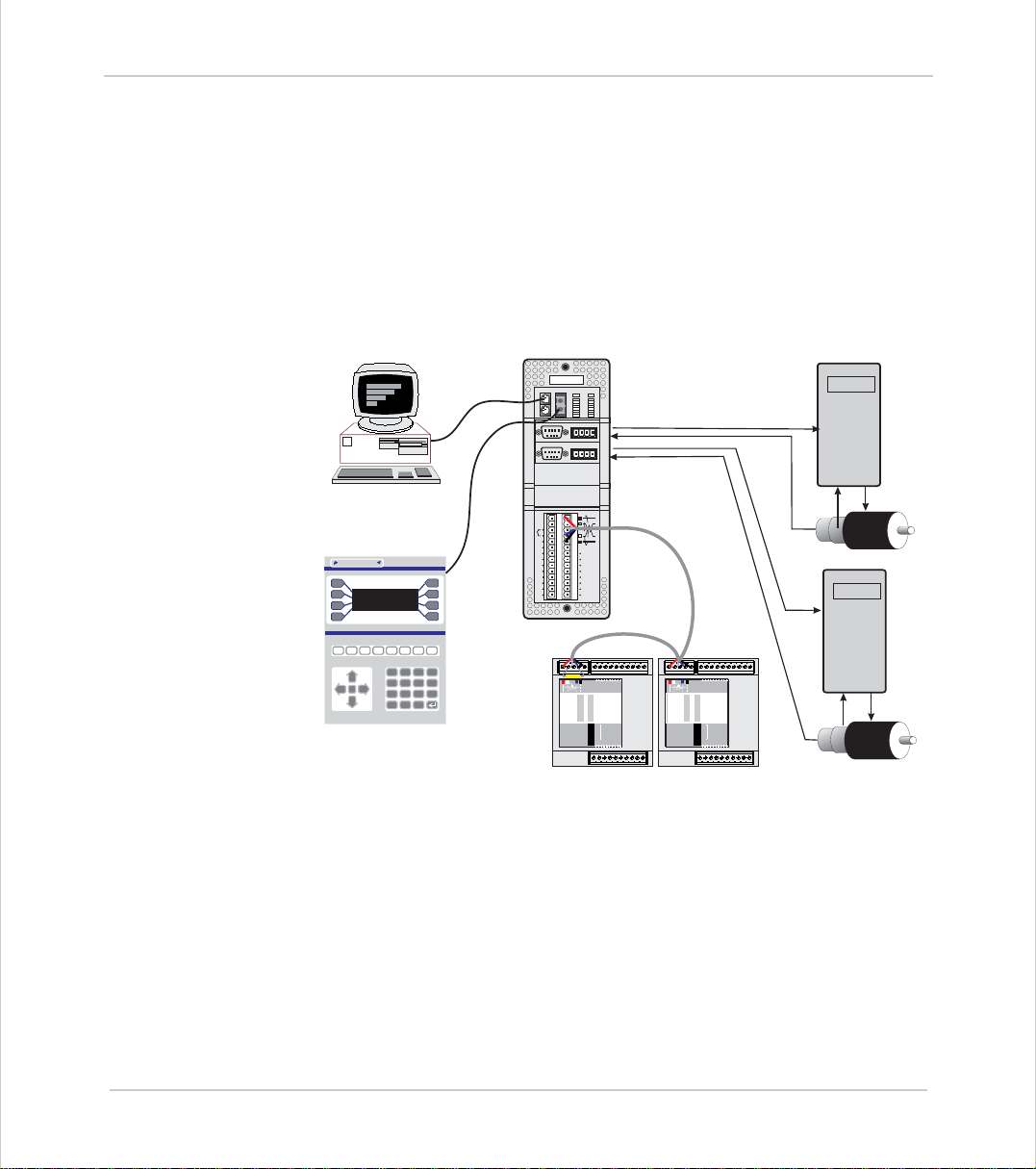
Trio Motion Technology’s range of Motion Coordinator products are designed to
enable the control of industrial machines with a minimum of external components. The products may be combined to build a control system capable of driving a mu lt i-axis machine and its auxil iary equip ment. The Motion Coordinator
system allows you to control up to 16 servo or stepper motors, Digital I/O and
additional equipment such as keypads and displays from a single master. Up to
fifteen masters can be networked together using the Trio fibre optic network
allowing up to 180 axes of control. The controller is programmed using the Trio
BASIC programming language. This may be used to build stand-alone programs or
commands ca n be sent from an external computer.
ENCODER
54321
9876
ENCODER
54321
9876
PCforProgramming
PCforProgramming
I0
I1
I2
TrioMotionTechnology
I3
I4
I5
I6
I7
24v
0v
MotionCoordinator
Trio
OKNET
STATUS
0
8
0
9
1
10
2
11
3
12
4
1
13
5
14
6
15
7
0v
V+ V- R
0v
V+ V- R
IO8
IO9
IO10
IO11
IO12
IO13
IO14
IO15
ServoDrive
Motor
ServoDrive
Y
9
7
4
1
-
OperatorInterface
8
N
6
5
CLR
3
2
.
0
MS NS
OFF
PR
DR
765432100v24v
0
8
1
9
Trio
2
10
3
11
4
12
13
5
CAN16 -I/O
14
6
15
7
1
2
4
NODE
ADDRESS
8
16
32
10 1112 13 14 1524v Ov98
CANI/O
MS NS
OFF
765432100v24v
0
8
1
9
Trio
2
10
3
11
4
12
13
5
CAN16 -I/O
14
6
15
7
1
2
4
NODE
ADDRESS
8
16
32
PR
DR
10 1112 13 14 1524v Ov98
Motor
Typical System Configuration
The
Motion
Coordin ator syst em is mo du lar, allow ing the user to ta ilor the co n troller
to th eir sp ecif ic n ee ds , bu t als o a llow i ng the fle xibi lity to inco rp ora te new mod ul es if
needs should change.
Introduction 1-3
Page 14
Trio Motion Technology
Setup and Programming
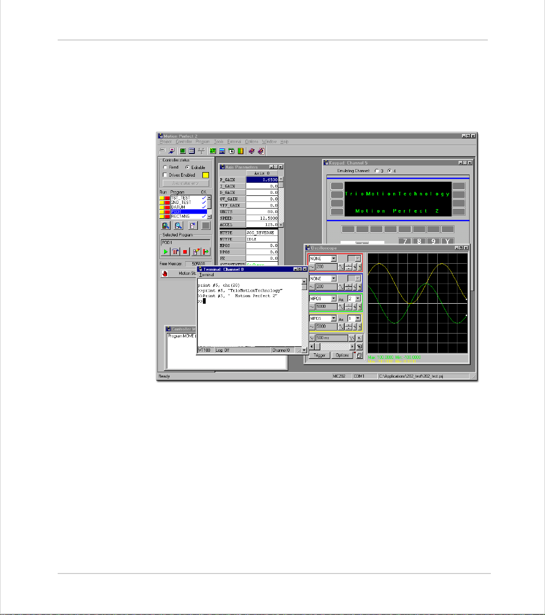
To program the
link. The dedicated
range of programming facilities, on an IBM PC or 100% compatible microcomputer
running W i nd ow s.
Motion
Motion
Coordinator a PC is connected via an RS-232 or USB serial
Perfect program is normally used to provide a wide
1-4 Introduction
Setup and Prog ramming
Motion Perfect
Once con ne cte d to the
BASIC, which provides an easy, rapid way to develop control programs. All the
standard progra m construct s are pr ovide d; v ari able s, loop s, in put/ o utpu t, m ath s
and c o nditions. Ext ensions to this b as i c instruc t io n se t ex i st to p e rmit a wide
variety of motion control facilities, such as single axis moves, synchronized multi
axis moves an d unsy nc hr onise d mu lti ax is mov es as w ell as the contr ol of th e
digital I/O.
Motion
The
MC216 and MC224. These controllers feature multi-tasking BASIC. Multiple
BASIC pro gra m s can b e cons tr uc ted an d ru n sim ultaneously to make pro gra m mi ng
comple x ap plic ati o ns mu ch easier.
Coordinato r ra nge c ur rently con s ists of th e M C 202 , M C20 6, Eur o 205 X,
Motion
Coordina tor, th e use r ha s dire ct ac ce ss to
Trio
Trio
Page 15

Motion Coordinator Technical Reference Manual
Products
The range of Trio
Motion
Coordinator products covered by this manual:
Motion Coordinator Master Controllers
Product
Code
P165 MC202 Compact, low cost DIN-rail mounting module features 1 1/2
P135 MC206 Low cost, h igh per form a nce DI N- ra il mou nt ing co nt rol ler fo r 1- 6
P150 Euro 205
P140 MC216 Flexible high performance master controller for 1-16 axes. 8
P170 MC224 Flexible high performance master controller for 1-24 axes. 8
Name Description
servo or 2 stepper axes. 4 Opto-isolated Inputs and 4 Optoisolated I/O channe ls are built in . Multi -taski ng Trio BASIC. I/O
expansion is via CAN bus.
axes. 8 Opto-isolated Inputs and 8 Opto-isolated Input/Output
channels,1 Opto-isolated analogue input, USB and memory stick
socket are built in. Multi-tasking Trio BASIC. I/O expansion is
via CAN bus.
For OEM a pp lic ati o ns, Trio o ffe r a 3U Eu roc ard fo rma t co nt r olle r
featuring 4 o nboard axes plus the option for a furthe r axis via a
standard Trio daughter board. 16 Opto-isolated Inputs and 8
Opto-isolated Output channels are built in. Multi-tasking Trio
BASIC. I/O expansion is via CAN bus.
Opto-isolated Inputs a nd 8 Opto-is olated I nput/Outpu t channe ls
are built in. Mult i-tasking Trio BASIC. I/O expansion is via CAN
bus.
Opto-isolated Inputs and 8 Opto-is o lated Input/Output
channels,2 Opto-isolated analogue in puts, USB and memory
stick socket ar e bu il t in . M u l t i- t askin g Trio BASIC. I/O
expansion is via CAN bus.
Introduction 1-5
Products
Page 16
Trio Motion Technology
Daughter Boards
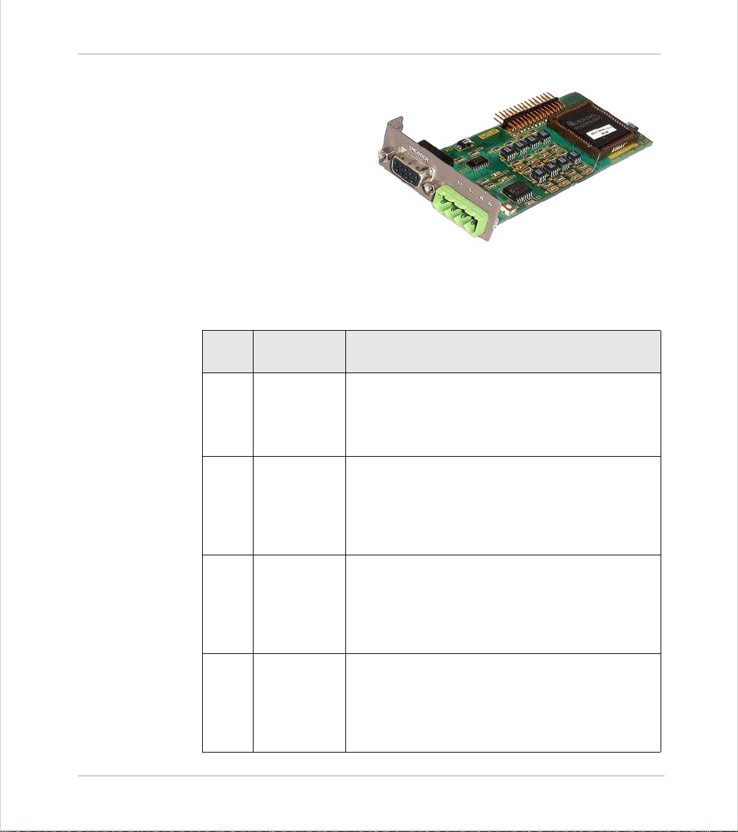
The Dau gh ter Bo ar d co nc ept
is a one of the key featu res
which give the
Coordin ator sy stem en orm ous
flexib i l ity i n its co nfiguratio n.
The Daughter Boards provide
the interfac e to many types
of Servo or Stepper Axes, plus
a numbe r of adva nc ed
communications options as well.
There are 13 types of daughter boards currently available:
Motion
Product
Code:
P200 Servo Encoder +/- 10v Output, Differential Encoder Input
P210 Servo Resolver +/- 10v Output, Resolver Input
P220 Reference
P230 Stepper Open-collector Step, Direction, Boost and Enable out-
Name Description
plus Hardware Registration Input
The servo encoder daughter board provides the interface to a DC or Brushless servo motor fitted with an
encoder or encoder emulation.
plus Hardware Registration Input
The servo resolver daughter board provides the interface to a DC or Brushless servo motor fitted with a
resolver. The resolver port provides absolute position
feedback within one motor turn.
Differential Encoder Input
Encoder
plus Hardware Registration Input
The encoder daughter board provides an encoder input
without any servo feedback facility for measurement,
registration and synchronization functions on conveyors, drums, flying shears, etc.
puts
The stepper daughte r board generates pulse s to drive
an external stepper motor amplifier. Single step, half
step and micro-stepping drives can be used with the
board.
1-6 Introduction
Products
Page 17
Trio Motion Technology
Product
Code:
P240 Stepper
P242 Hardware
P260 Analogue Out-
P270 SSI Absolute
P280 Differential
Name Description
Encoder
Pswitch
put
Servo
Stepper
Open-collector Step, Direction, Boost and Enable outputs plus Differential Encoder Input.
The stepper daughter board with position verification
has all the features of the simpler stepper daughter
board. Pos ition verification is added to a stepper axis
by providing encoder feedback to check the position of
the motor.
Differential Encoder Input
plus Hardware Position Switch Outputs
The hardware PSWITCH daughter board allows 4 opencollector outputs to be switched ON and OFF at programmed positions. This function is similar to the
PWITCH command which is implemented in the system
software and allows outputs to be switc hed ON and OFF
over defined position sec t o rs . The Hardware PSWITCH
daughter board performs the position comparison in
electronic hardware on the daughter board. This allows
the pulses generated to be very accurat ely timed.
+/- 10v Output with direct DAC control
The voltage output daughter board provides a 12 bit +/10v voltage output for driving inverters and other
devices. The boa rd is a s implif ied s ervo da ughter boa rd
and the con ne ct i ons ar e s imi la r.
+/- 10v Output, Differential Encoder Input
plus Hardware Registration Input
The servo resolver daughter board provides the interface to a DC or Brushless servo motor fitted with an
absolute encoder fitted with a Synchronous Serial Interface (SSI).
Differential Line Driver outputs for Step, Direction,
Boost and Enable, plus Hardware Registration Input
The differential s tepper daughter board is a stepper
daughter board wit h the output signals provide d as differential 5 volt signals on a 15 way 'D' connector. The
daughter board does not f eature an encoder port for
position verific atio n, but does hav e a regi st ration i nput
to allow for capture of the number of step pulses when
a registration signals arrives.
1-7 Introduction
Products
Page 18

Trio Motion Technology
Product
Code:
P290 CAN Digital Link to CANBus drives
P291* SERCOS Digital Link to SERCOS drives
P292 SLM (Drivelink) Digital Link to SLM drives
P295 USB Interface Universal Serial bus interface for high-speed PC
Name Description
The combination of the motherboard CAN channel and
the ability to add up to 4 CAN daughter boards allows
the MC216 to potentially control up to 5 CAN channels.
The SERCOS daughter board provids digital con t rol to
appropriate s ervo drives via a Fibre Optic loop. Up to 8
axes can be connected to each P291, which allows the
MC224 to cont rol up to 24 ax es.
The SLM daughter board is aimed at providing digital
control channels for servo drives utilising the SLM protocol.
communications
The USB daughter board provides a very high speed
interface between the motion coordinator and a host
PC fitted with a USB port. Support for this high speed
interface is in cl uded in Trio's MotionP erfect 2 application and software libraries are in development to allow
developers to support the interfac e within their own
programs.
1-8 Introduction
Products
P296* Ethernet Ethernet LAN Interface
The Ethernet daughter board enables the Motion Coordinator to be connected to a local factory or office network. Supports TCP/IP using the 10Base-T physical
layer.
P297 Profibus Profibus Fieldbus Interface
With the P rof ibus Daughter Board and appropriate software on the Motion Coordinator, it is possible to connect to external devices using the Profibus protocol.
*
(Ava ilable for use w ith M C 20 6 and M C2 24 only )
Custom Daughter Boards
T rio can produce custom daughter boards for specific customer applications where
required.
Page 19
Trio Motion Technology
I/O Expansion options
Prod.
Code
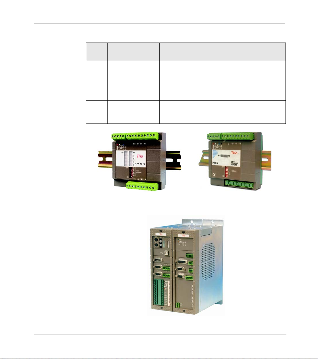
P315 CAN 16 IO DIN Rail mounted 24v I/O expander module pro-
P325 CAN Analog Inputs DIN Rail mounted +/- 10v A nalog Input module pro-
P300 Axis Expander Expansion module pro vides housing for up to 4
Name Description
vides 16 opto-isolated channels each of which may
be used as an Input or an Output.
vides 8 opto-isolated channels.
additional axis dau ghter board s. Up to 3 connect to
the MC216
P315 - CAN-16 I /O
P325 - CAN-8 Analog Inputs
1-9 Introduction
Products
MC216 Shown with P300 Axis Expander
Page 20
Trio Motion Technology
Operator Interfaces
Name Name Description
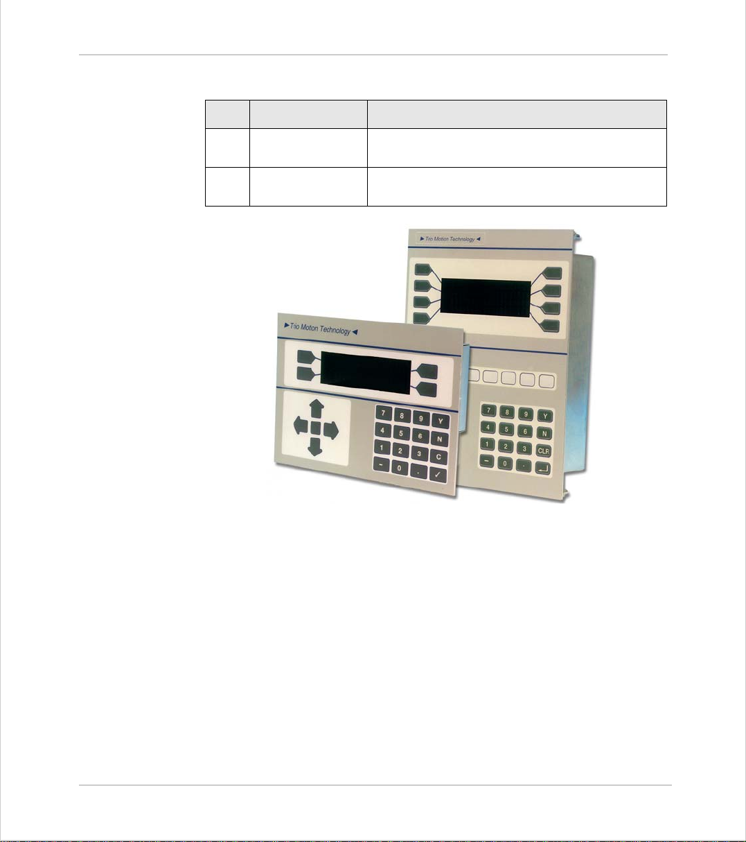
P502 Mini-Membrane
Keypad
P503 Membrane Keypad High performance general purpose operator key-
Compact operator keypad/display
pad/display
1-10 Introduction
Products
Page 21
Motion Coordinator Technical Reference Manual
TrioMotionTechnology
System Buildi ng
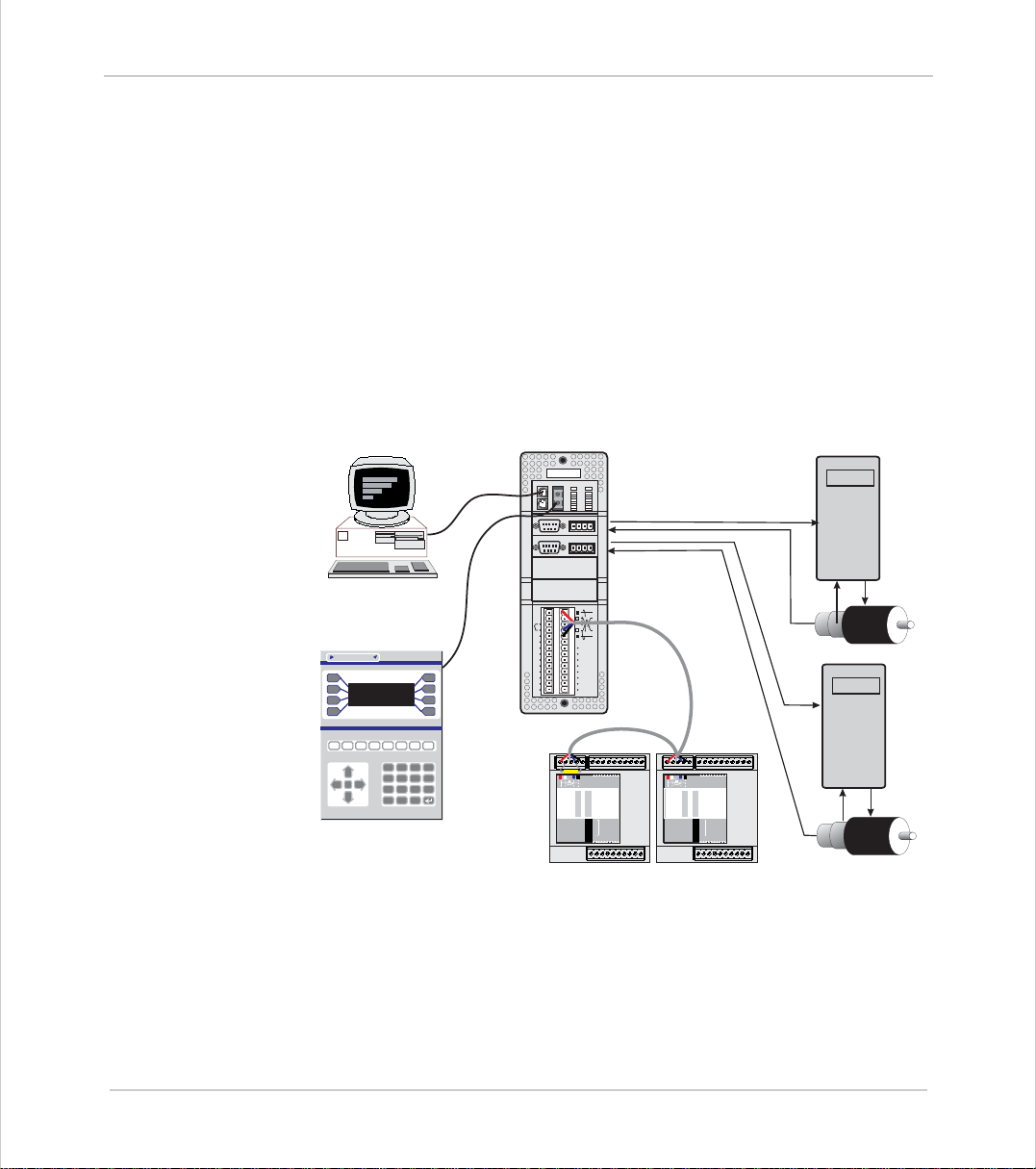
The modules and boards may be mixed within the system rules:
1) Every system must start with one Motion Coordinator master unit as thi s contains
the processor and logic power supply for the system.
2) The MC216 master unit can house up to 4 daughter boards. The Euro 205 and
MC206 will accept a single daughter board. These can be of any type.
3) The MC216 can have up to 3 axis expander modules added to house up to 16
daughter boards. 4 being housed in the Master and 4 in each of the axis expanders.
4) Up to 16 CAN-16 I/O and 4 CAN Anal og Input modules can be connected to any
Motion Coordinator.
ENCODER
54321
9876
ENCODER
54321
9876
PCforProgramming
PCforProgramming
Trio
STATUS
OKNET
0
8
0
9
1
10
2
11
3
12
4
1
13
5
14
6
15
7
0v
V+ V- R
0v
V+ V- R
ServoDrive
TrioMotionTechnology
OperatorInterface
I0
I1
IO8
I2
IO9
I3
IO10
I4
IO11
I5
IO12
I6
IO13
I7
IO14
24v
IO15
0v
MotionCoordinator
Y
9
7
8
N
6
4
5
CLR
3
1
2
.
-
0
MS NS
OFF
PR
DR
765432100v24v
8
0
9
1
Trio
10
2
11
3
4
12
13
5
CAN16 -I/O
14
6
15
7
1
2
4
NODE
ADDRESS
8
16
32
10 1112 13 14 1524v Ov98
MS NS
OFF
765432100v24v
8
0
9
1
Trio
10
2
11
3
4
12
13
5
CAN16 -I/O
14
6
15
7
1
2
4
NODE
ADDRESS
8
16
32
PR
DR
10 1112 13 14 1524v Ov98
CANI/O
Motor
ServoDrive
Motor
Typical System Configuration
Introduction 1-11
System Building
Page 22
Trio Motion Technology
System Examples
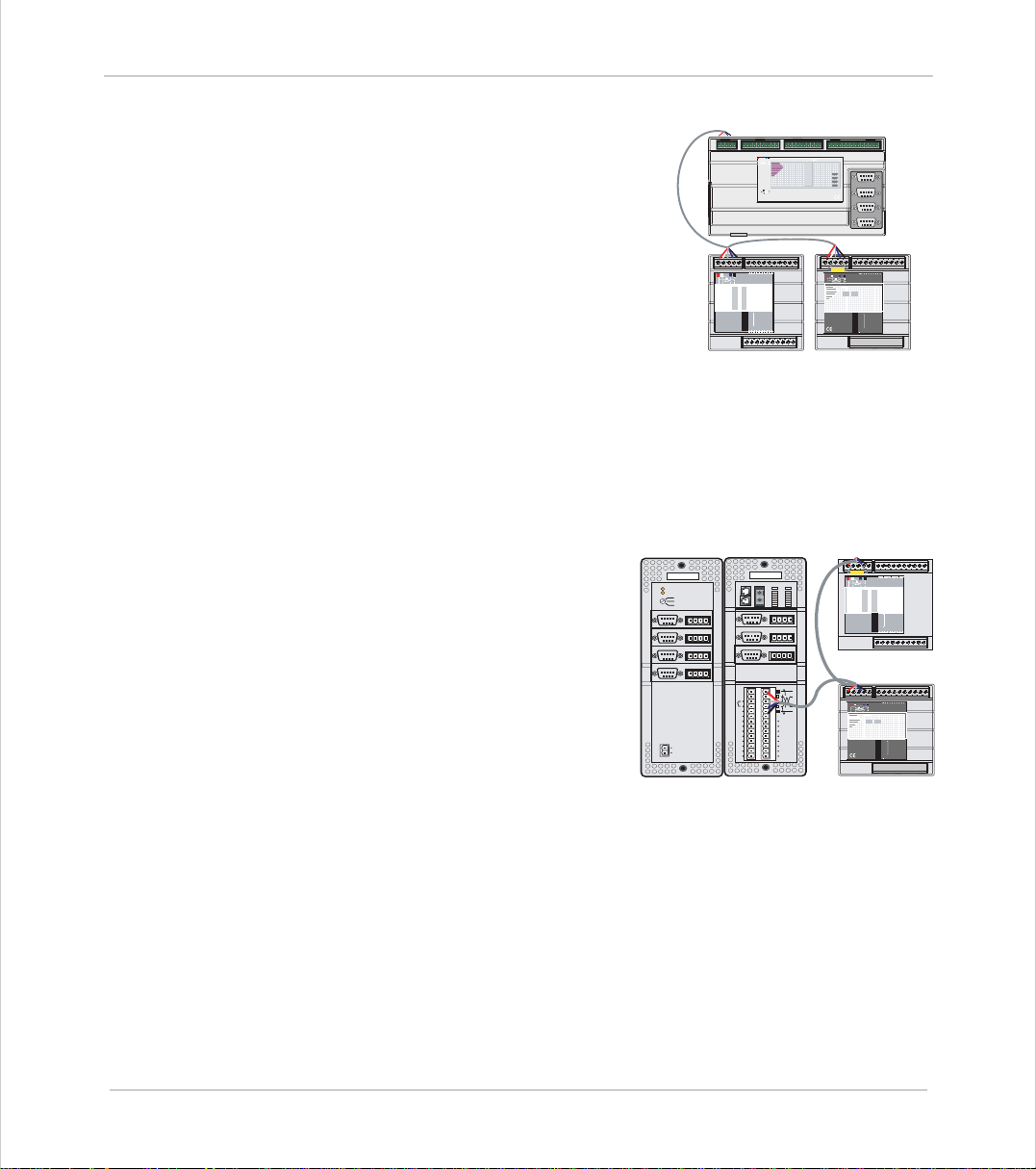
Example 1
Example 2
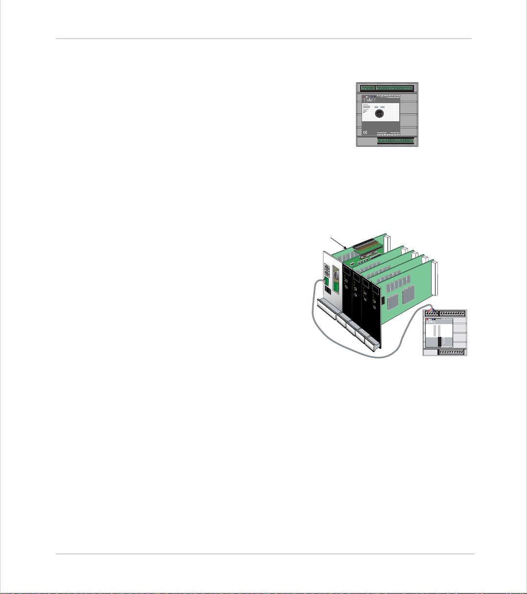
Simplest Possible System - Single MC202
• 1½ Axis Servo (Servo + reference encoder)
or 2 Axis Stepper
• 8 Cha nn els of 24v I/O on board
- 4 Inp uts
- 4 I/O
Euro205, 5 Axis Rackmounted System
EURO205
The Euro 205 controller provides a
compa ct ra ck- m ou nte d con tro lle r ide al
for volume OEM applications.
The four in ternal axes ar e configured
as stepper axes and connected via
the backplane to third party stepper
drives.
An optional P200 Servo Da ughter
Board provides a fifth axis connected
to a servo drive.
012389101124v
0vV+V-
Input/Outputs
Trio
MC202
Motion
P165
Coordinator
AXIS 0
AXIS 1
012345
012345
5v 0v
765432100v24v
MS NS
0
8
1
9
Trio
2
10
3
11
4
12
5
13
CAN16 -I/O
6
14
7
15
OFF
1
2
4
NODE
ADDRESS
8
16
32
16
PR
32
PR
DR
1011 12 1314 15 24vOv98
DR
CAN-16 I/O
1-12 Introduction
Syst em Build ing
•5 servo axes
• 32 Channels of 24v I/O
- 8 in + 8 I/O on MC204, plus
- 16 I/O on CAN-16 I/O expander
Page 23
Motion Coordinator Technical Reference Manual
Example 3
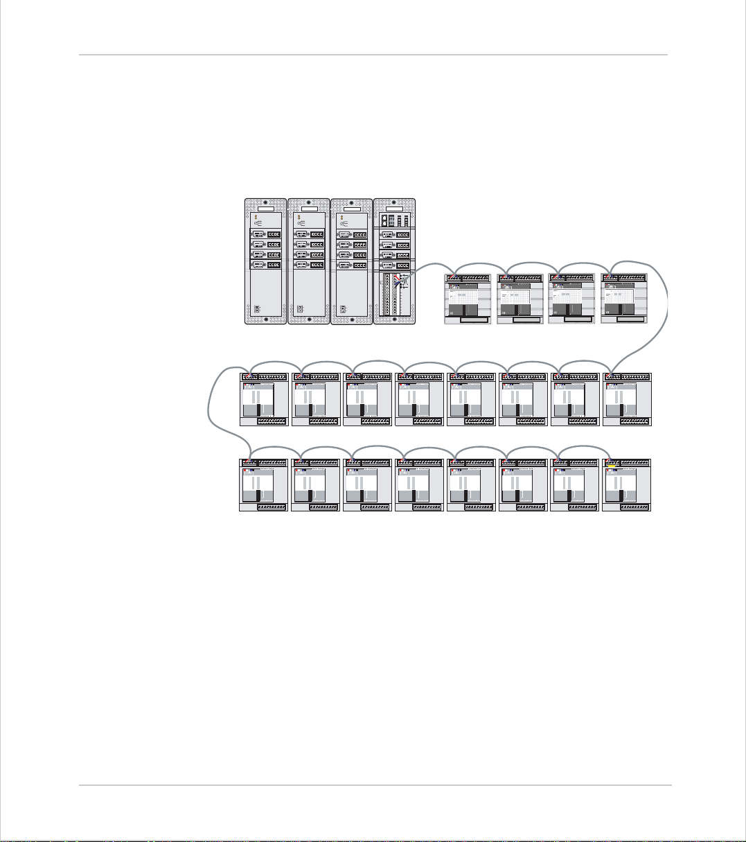
Example 4
MC206 - 5½ Axis Servo System
Utilising the four internal axis as servo
axes, an optional servo daughter board and
the refere nc e en co de r in put to pro v ide a
total of 5 servo axes plus the reference
(master) encoder.
The MC20 6 ha s 16 cha nn els of 24v I/O as
standard, this is expanded up to 32
channels with the add ition of a C AN-16 I/O
module. 8 Analo g Input s (+/- 10 v) are
provided by the CAN Analog Inputs module.
• 5 ser vo / steppe r axes
• 32 Channels of 24v I/O
- 8 in + 8 I/O on MC206, plus
- 16 I/O on CAN-16 I/O expander
•8 Analog Input Channels
MC216 - 7 Axis System
The system comprises an MC216 Master
with and additio nal th ree axe s in the
optional Axis Expander module. The
axes can be any com b inat ion of servo
and stepper drives determined by the
daughter boards used.
The MC2 16 has 16 c hannels of 24v Digital
I/O as standard, this is expanded up to
32 with the ad d ition of a C AN -16 I/O
module. 8 Analo g Input s (+/- 10 v) are
provided by the CAN Analog Inputs
module.
Trio
OK
24v
04 - 07
08 - 11
12 - 15
ENCODER
V+ V- R
54321
9876
ENCODER
V+ V- R
54321
9876
ENCODER
V+ V- R
54321
9876
ENCODER
V+ V- R
54321
9876
I0
I1
I2
I3
I4
I5
I6
I7
24v
24v
0v
0v
Axis
Expander
MC206 + Daughter Board
MS NS
0
8
1
9
2
10
3
11
4
12
13
5
14
6
15
7
1
OFF
2
4
8
16
32
PR
PR
DR
DR
CAN-16 I/O
ENCODER
0v
54321
9876
ENCODER
0v
54321
9876
ENCODER
0v
54321
9876
0v
I0
I1
I2
IO8
I3
IO9
I4
IO10
I5
IO11
I6
IO12
I7
IO13
24v
IO14
0v
IO15
MC216
765432100v 24v
Trio
CAN16 -I/O
NODE
ADDRESS
16
32
1011 12 1314 15 24vOv98
0
1
SERIAL A
SERIAL B
Trio
0vA012 3 4 5 6 7 0v 24v 8 9
MC206
Motion
Coordinator
P135
OKNET
STATUS
0
1
2
3
4
5
6
7
V+ V- R
V+ V- R
V+ V- R
IO8
IO9
IO10
IO11
IO12
IO13
IO14
IO15
0v
0v
0v
1011 12 1314 15E-A/AB/BZ/ZV-
V0V1 V2V3
OK
STATUS
0
Trio
1
2
Axis 0
3
4
Axis 1
5
Axis 2
6
7
Axis 3
MS
P325
OFF
CAN Analog Inputs
8
9
10
11
12
13
14
15
CAN Analog Inputs
5 4 3 2 1
9 8 7 6
5 4 3 2 1
9 8 7 6
5 4 3 2 1
9 8 7 6
5 4 3 2 1
9 8 7 6
765432100v24v
Trio
018
NS
9
CAN Analog
Inputs
1
2
NODE
4
ADDRESS
8
16
32
PR
DR
765432100v24v
MS NS
8
0
9
1
10
2
11
3
4
12
13
5
CAN16 -I/O
14
6
15
7
1
OFF
2
4
NODE
ADDRESS
8
16
32
PR
DR
1011 12 1314 15 24vOv98
CAN-16 I/O
018
NS
MS
9
CAN Analog
P325
Inputs
OFF
1
2
4
8
16
32
PR
DR
Trio
765432100v 24v
Trio
NODE
ADDRESS
•7 axes
- 4 on MC216 Master, plus
- 3 on Axis Expander
• 32 Channels of 24v I/O
- 8 in + 8 I/O on MC204, plus - 16 I/O on CAN-16 I/O expander
•8 Analog Input Channels
Introduction 1-13
System Building
Page 24
Trio Motion Technology
Example 5
MC216 - 16 axis system with maximum I/O expansion
The example system illustrated below shows an MC216 controller with the
maximum possible I/O expansion. Applications for a system of this complexity
might include collating or packag ing mac hi ne ry wh e re th er e ar e m ult iple o pe rations performed on a product and many I/O are used for sensors etc.
MS NS
MS NS
Trio
OKNET
STATUS
0
8
0
9
1
10
2
11
3
12
4
1
13
5
14
6
15
7
0v
V+ V- R
ENCODER
0v
V+ V- R
54321
9876
0v
V+ V- R
ENCODER
0v
V+ V- R
54321
9876
0v
V+ V- R
ENCODER
0v
V+ V- R
54321
9876
0v
V+ V- R
ENCODER
0v
V+ V- R
54321
9876
I0
I1
I2
IO8
IO8
I3
IO9
IO9
I4
IO10
IO10
I5
IO11
IO11
I6
IO12
IO12
I7
IO13
IO13
24v
IO14
IO14
0v
IO15
IO15
765432100v 24v
Trio
018
NS
MS
9
CAN Analog
Inputs
P325
OFF
1
2
NODE
4
ADDRESS
8
16
32
PR
DR
765432100v 24v
Trio
018
NS
MS
9
CAN Analog
Inputs
P325
OFF
1
2
NODE
4
ADDRESS
8
16
32
PR
DR
MC216
MS NS
765432100v24v
0
8
1
9
Trio
2
10
3
11
4
12
5
13
CAN16 -I/O
6
14
7
15
OFF
1
2
4
NODE
ADDRESS
8
16
32
PR
DR
1011 1213 1415 24vOv98
MS NS
765432100v24v
0
8
1
9
Trio
2
10
3
11
4
12
13
5
CAN16 -I/O
14
6
15
7
OFF
1
2
4
NODE
ADDRESS
8
16
32
PR
DR
1011 1213 1415 24vOv98
765432100v24v
0
8
1
9
Trio
2
10
3
11
4
12
5
13
CAN16 -I/O
6
14
7
15
1
OFF
2
4
NODE
ADDRESS
8
16
32
PR
DR
1011 1213 1415 24vOv98
MS NS
765432100v24v
0
8
1
9
Trio
2
10
3
11
4
12
5
13
CAN16 -I/O
6
14
7
15
OFF
1
2
4
NODE
ADDRESS
8
16
32
PR
DR
1011 1213 1415 24vOv98
765432100v 24v
Trio
018
NS
MS
9
CAN Analog
Inputs
P325
OFF
1
2
NODE
4
ADDRESS
8
16
32
PR
DR
CAN Analog Inputs
765432100v24v
MS NS
0
8
1
9
Trio
2
10
3
11
4
12
5
13
CAN16 -I/O
6
14
7
15
OFF
1
2
4
NODE
ADDRESS
8
16
32
PR
DR
1011 1213 1415 24vOv98
765432100v 24v
Trio
018
NS
MS
9
CAN Analog
Inputs
P325
OFF
1
2
NODE
4
ADDRESS
8
16
32
PR
DR
765432100v24v
MS NS
0
8
1
9
Trio
2
10
3
11
4
12
13
5
CAN16 -I/O
14
6
15
7
OFF
1
2
4
NODE
ADDRESS
8
16
32
PR
DR
1011 1213 1415 24vOv98
CAN-16 I/O
MS NS
765432100v24v
8
0
9
1
Trio
10
2
11
3
4
12
5
13
CAN16 -I/O
6
14
7
15
1
OFF
2
4
NODE
ADDRESS
8
16
32
PR
DR
1011 1213 1415 24vOv98
MS NS
765432100v24v
8
0
9
1
Trio
10
2
11
3
4
12
13
5
CAN16 -I/O
14
6
15
7
1
OFF
2
4
NODE
ADDRESS
8
16
32
PR
DR
1011 1213 1415 24vOv98
765432100v24v
8
0
9
1
Trio
10
2
11
3
4
12
13
5
CAN16 -I/O
14
6
15
7
1
OFF
2
4
NODE
ADDRESS
8
16
32
PR
DR
1011 1213 1415 24vOv98
MS NS
765432100v24v
8
0
9
1
Trio
10
2
11
3
4
12
5
13
CAN16 -I/O
6
14
7
15
1
OFF
2
4
NODE
ADDRESS
8
16
32
PR
DR
1011 1213 1415 24vOv98
MS NS
765432100v24v
8
0
9
1
Trio
10
2
11
3
4
12
5
13
CAN16 -I/O
6
14
7
15
1
OFF
2
4
NODE
ADDRESS
8
16
32
PR
DR
1011 1213 1415 24vOv98
MS NS
765432100v24v
8
0
9
1
Trio
10
2
11
3
4
12
13
5
CAN16 -I/O
14
6
15
7
1
OFF
2
4
NODE
ADDRESS
8
16
32
PR
DR
1011 1213 1415 24vOv98
Trio
OK
24v
04 - 07
08 - 11
12 - 15
ENCODER
0v
V+ V- R
54321
9876
ENCODER
0v
V+ V- R
54321
9876
ENCODER
0v
V+ V- R
54321
9876
ENCODER
0v
V+ V- R
54321
9876
I0
I1
I2
IO8
I3
IO9
I4
IO10
I5
IO11
I6
IO12
I7
IO13
24v
24v
IO14
0v
0v
IO15
Axis Expanders
765432100v24v
MS NS
0
8
1
9
Trio
2
10
3
11
4
12
5
13
CAN16 -I/O
6
14
7
15
1
OFF
2
4
NODE
ADDRESS
8
16
32
PR
DR
1011 1213 1415 24vOv98
765432100v24v
MS NS
8
0
9
1
Trio
10
2
11
3
4
12
13
5
CAN16 -I/O
14
6
15
7
1
OFF
2
4
NODE
ADDRESS
8
16
32
PR
DR
1011 1213 1415 24vOv98
Trio
OK
24v
04 - 07
08 - 11
12 - 15
ENCODER
54321
9876
ENCODER
54321
9876
ENCODER
54321
9876
ENCODER
54321
9876
I0
I1
I2
I3
I4
I5
I6
I7
24v
24v
0v
0v
MS NS
0
1
2
3
4
5
6
7
OFF
PR
DR
MS NS
0
1
2
3
4
5
6
7
OFF
PR
DR
Trio
OK
24v
04 - 07
08 - 11
12 - 15
0v
V+ V- R
ENCODER
54321
9876
0v
V+ V- R
ENCODER
54321
9876
0v
V+ V- R
ENCODER
54321
9876
0v
V+ V- R
ENCODER
54321
9876
I0
I1
IO8
I2
IO9
I3
IO10
I4
IO11
I5
IO12
I6
IO13
I7
24v
IO14
24v
0v
IO15
0v
765432100v24v
8
9
Trio
10
11
12
13
CAN16 -I/O
14
15
1
2
4
NODE
ADDRESS
8
16
32
1011 1213 1415 24vOv98
765432100v24v
8
9
Trio
10
11
12
13
CAN16 -I/O
14
15
1
2
4
NODE
ADDRESS
8
16
32
1011 1213 1415 24vOv98
1-14 Introduction
Syst em Build ing
CAN-16 I/O
•16 Axes (Any type)
• 272 C han nels of 24v I/O
- 8 in + 8 I/O on MC216, plus
- 256 I/O (16 * 16) on the 16 CAN-16 I/O modules
• 32 Analog Input Channels (8 per module)
Page 25

Motion Coordinator Technical Reference Manual
F eatures and Typical Applications
Trio
BASIC contains accurate motion control functions for the generation of complex
movements of various types, including:
• Linear interpolation of up to 24 axes
• Circular and helica l in te rp ol at io n
• Variable speed and acceleration profiles
• Electronic gearboxes
• Electronic cam profiles
The operator interface may be achieved by any combination of the following:
• Dedicated host computer (connected via USB or RS-232 serial po rt)
• Membrane Keypad with Vacuum Fluorescent Display
• Dedicated Operator Panel using the’Modbus’ serial protocol.
• Switches / Thumbwheels
• Status lamps
The system is able to control a wide range of mechanisms and equipment including:
• Brushl ess servo mo to rs
• Stepper motors
• Br ushed DC servo motors
•Hydraulic servo valves
• Hydraulic proportional valves
• Pneumatic/hydraulic solenoids
• Relays/contactors
Typical applications:
• Cut to length • Coil winding • Automotive welding
• Flying shears • Laser guidance • Spark erosion
• Glue laying • Electronic assembly • Drilling
• We b control • Printi ng • Milling
• Tension control • Collating
• Pick & Place • Packaging • YOUR application
Introduction 1-15
System Building
Page 26
Trio Motion Technology
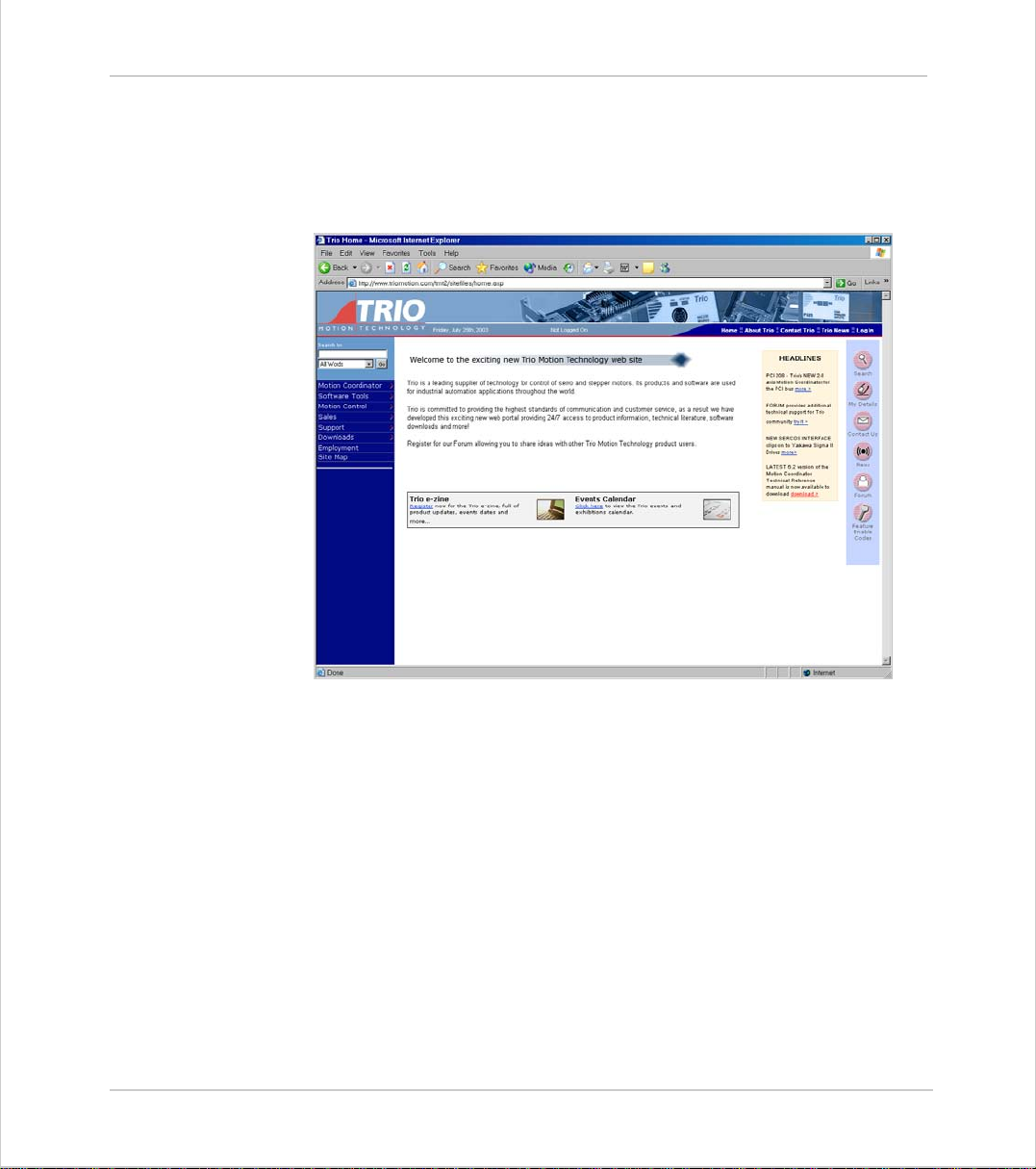
The Trio Motion Technolo gy Website
The Trio website con tain s up to the m inu te n ew s , info rm at ion an d supp ort for the
Motion
Coordinator product range.
1-16 Introduction
Syst em Build ing
Website Features
•Latest News
• Product Information
•Manuals
• Support S o ftware
• System Software Upda tes
• Technical Supp o rt
• U ser’s Forum
• Application Examples
• E mployment Opportunities
WWW.TRIOMOTION.COM
Page 27

CHAPTER
CHAPTER 0HARDWARE OVERVIEW
Page 28

Page 29
Motion Coordinator Technical Refe ren ce Ma n ual
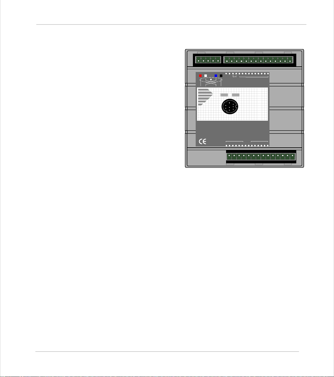
Motion Coordinator MC20 2
Overview
Programmin g
I/O C a pability
The MC202 is a miniature stepper/servo positioner with the
built-in ability to co ntrol one
012389101124v
servo/stepper axis with addi-
0vV+V-
Input/Outputs
tional s ynchro nisati on enco der, or
two stepper axes.
Trio
The MC202 is de s ig ned to p r ovi de
a compact, low cost, easy to use
unit for OEM machine builders.
P165
MC202
Motion
Coordinator
It is designed to be configured
and programmed for the application with a PC r unning th e Motion
AXIS0
012345
5v 0v
AXIS1
012345
Perfect application, and then
may be se t t o ru n “s tan dalo ne ” if
an external computer is not
required for the final system.
The Multi-tasking ability of the MC202 allows parts of a complex application to be
developed, tested and run independently, although the tasks can share data and
motion control hardware. On the MC202 up to 3 Trio BASIC programs can be run
simultaneously.
The MC202 has 4 built in 24v inputs and 4 built-in bi-directional input/output
channels. These may be used for system interaction or may be defined to be used
by the controller for end of travel limits, datuming and feedhold functions if
required. The MC202 can have up 256 external Input/Output channels and up to
32 analog input channels connected using DIN rail mounted I/O modules. These
units co nnect to the built-in CAN channel of the MC202
Communications
The MC202 has a built-in RS-232 port. A further serial channel is available at TTL
levels. External adapters are available to allow this serial port to be linked to a
full-duplex RS485 channel or a Trio membrane keypad on a fibre-optic link.
If the bu ilt-in CAN connectio n is not being us e to for I/O modules it may be used
for CAN communications.
Hardware Overview 2-3
Motion Coordinator MC202
Page 30
Trio Motion Technology
Connections to the MC202
Wiring
Connectors
Note:
All wires and cables should be of suitable size and type for the signals carried and
the operating environment.
Suitable wires would include multi-core screened cable for encoder feedback and
the serial links. The analog output from the MC202 (if used) should be connected
to the servo drive via a screened twisted pair. Drive enable outputs and 24v
inputs do not have a large cu rrent requiremen t so the ch o ice of wire i s not critical.
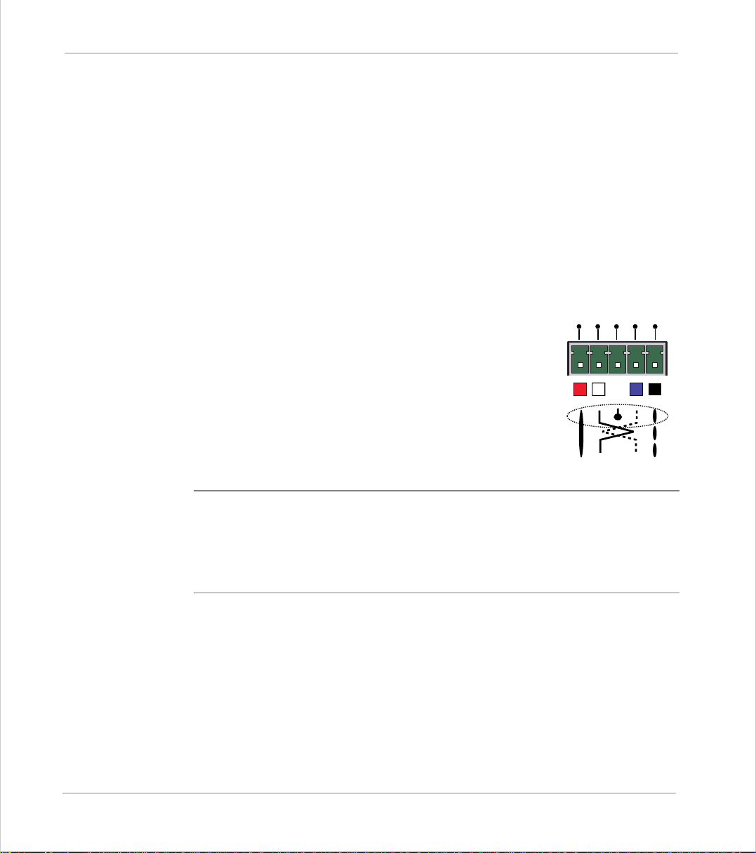
Top 5-Way Connector
This is a 5 way 3.81mm pitch connector. The connector is
used both to provide the 24 volt power to the MC202 and
provide connec tions for I/O expansion via Trio's P315 and
V+
CAN
P325 CAN I/O expanders. 24 volts must be provided as this
powers the unit.
This 24 volt input is internally isolated from the I/O 24 volts
and the +/-10v voltage output. The MC202 has internal
power supply filters for the 24v power supply. This supply
should be isolated and independent from the I/O 24v.
The CAN connections are optional, although the CAN Screen must be
connected to E ar th in all cases.
H
SHIELD
CAN
L
V-
The V+(24v) and V- MUST be connected as this powers the MC202.
Power supply: 24V dc, Class 2 transformer or po wer source.
2-4 Hardware Overview
Motion Coordinator MC202
Page 31
Motion Coordinator Technical Refe ren ce Ma n ual
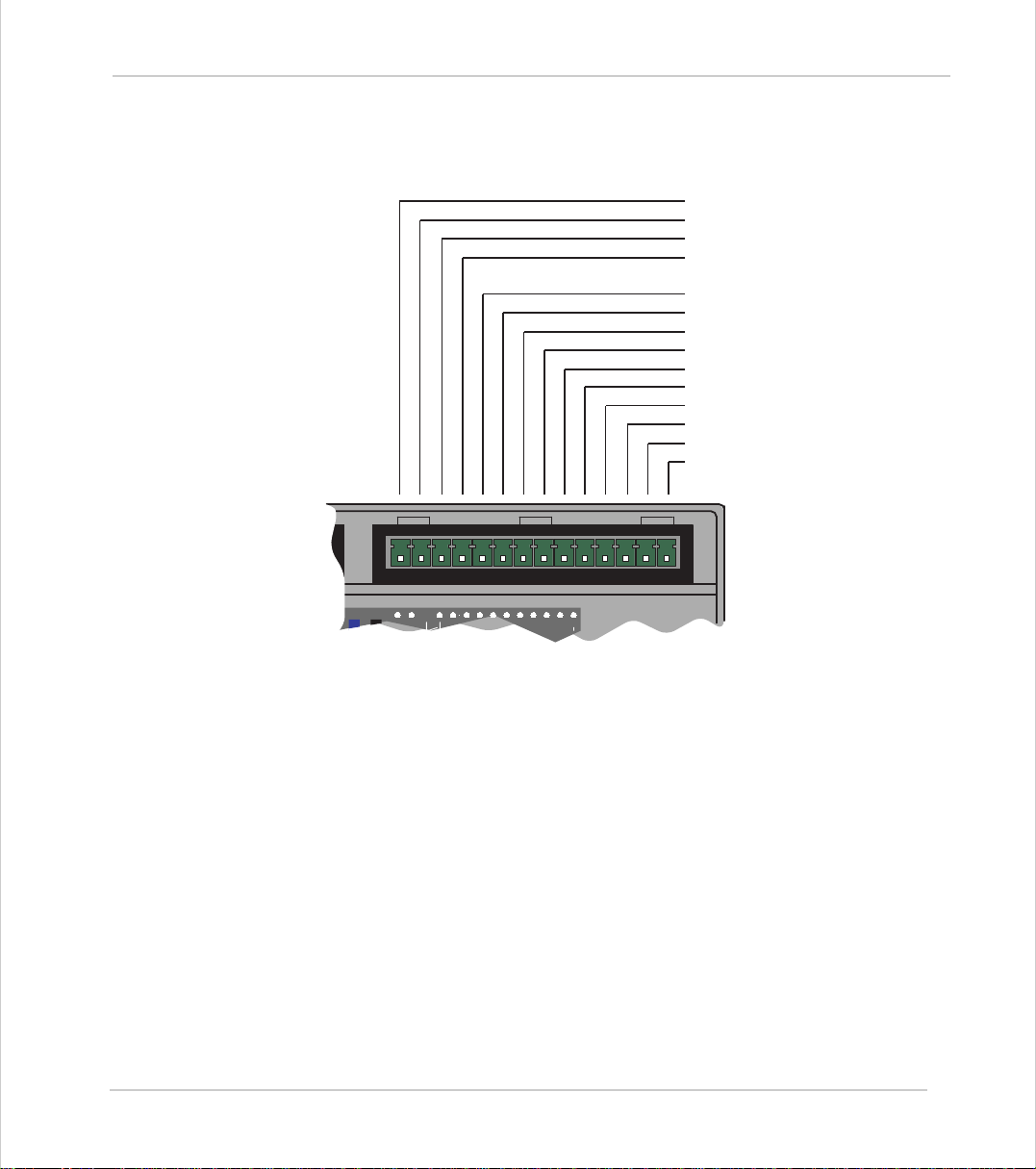
Top 14 Wa y Conn ector :
This is a 14 way 3.81 pitch connector. The connector provides for the +/-10volt
analog output, the enable relay contacts, and the I/O connections.
Vout Vout +
Amplifier Enable A
Amplifier Enable B
I/O 0 Volts
I/O 24 Volts
Input 0 / Registration Axis 0
Input 1 / Registration Axis 1
Input 2
Input 3
I/O Channel 8
I/O Channel 9
I/O Channel 10
I/O Channel 11
012389101124v0vV+V-
Analog Output
This feature when required is used to drive a servo drive or inverter connected to
axis 0. The +/-10 volt analog ou tput is is ol ate d fr om the power in put an d the I /O
modules of the MC202 and is powered via an internal DC-DC converter. The pair
of connections should be connected by a screened cable to the drive input.
The drive enable pins are used to interlock the MC202 with a servo OR stepper
drive and should be used in all cases. The connections are internally connected
to a pair of normally open relay contacts which close when the drive is enabled.
I/O Power Inputs
The I/O 0 Volts and I/O 24 Volts are used to power the 24 volt inputs and outputs.
The I/O connections are isolated from the module power inputs on the 5-way
CAN connector . The I/O 0 Volts connection must be made if any inputs or outputs
are used. The I/O 24 Volts is only required to power outputs and may be omitted
if none are us ed. The I/O channels 8 to 11 are bi-directional and can be u sed
Hardware Overview 2-5
Motion Coordinator MC202
Page 32
Trio Motion Technology
either as an input or an output. They a re num b ered fr om 8 to 11 fo r gr e ate r c ompatibility with other Trio Motion Coordinators. The i nput s c han nel s 0 to 3 are n ot
bi-directional. Inputs 0 and input 1 can be used as registration inputs for axes 0
and 1 for use with the
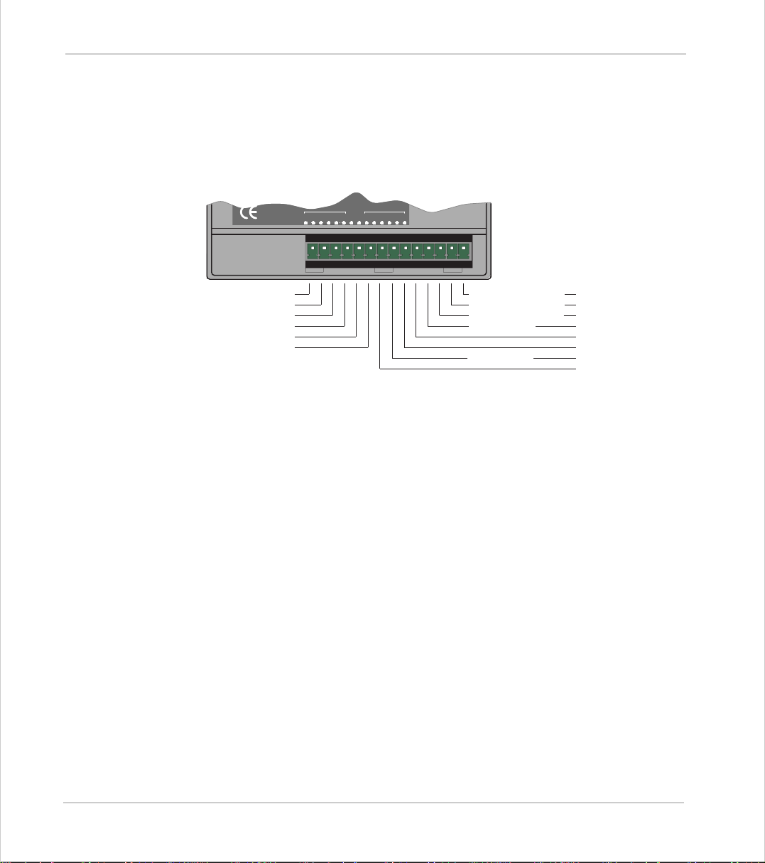
Bottom 14 Way Connector:
REGIST command.
A AXIS 0
/A AXIS 0
B AXIS 0
/B AXIS 0
Z AXIS 0
/Z AXIS 0
AXIS0
012345
012345
5v 0v
AXIS1
DIRECTION AXIS 1
STEP AXIS 1
DIRECTION AXIS 0
STEP AXIS 0
0v Stepper
/Z AXIS 1
Z AXIS 1
/B AXIS 1
B AXIS 1
/A AXIS 1
A AXIS1
0v Encoder
5v Encoder Output
This is a 14 way 3.81 pi tch connector. The conn ect o r p r ovi d es for 2 axes o f 5 v di fferential encoder inputs, 2 axes of step and direction encoder inputs and a 5 volt
output for powering ext ernal e ncoder only.
Axis 0 Encoder Inputs:
6 pins are used to provide dedicated encoder inputs for Axis 0. If axis 0 is used as
a stepper axis these connections are not required. The inputs are 5 volt differential encoder inputs. The inputs must be connected to the encoder via a screened
cable and the screen connected to the panel ground.
Encoder Power Supply:
2 pins provide a low power output at 5v (150mA maximum). This supply is provided for driving one or two encoders (if current consumption permits). The
power sup plie s sh ould b e incl ude d withi n the en cod er scre en ed cabl e. Do not use
the 0V as a screen ground point.
Stepper Outputs / Axis 1 Encoder Inputs:
6 pins are used to provide encoder inputs for Axis 1. Alternatively 4 of the pins
can be used as step and direction open-collector outputs for axes 0 and 1. The
inputs are 5 volt differential encoder inputs. Whatever the use of the pins they
must be connected to the stepper d rive or encoder us in g screened cab le a n d the
screen connected to the panel ground.
2-6 Hardware Overview
Motion Coordinator MC202
Page 33
Motion Coordinator Technical Refe ren ce Ma n ual
Serial Port Connections
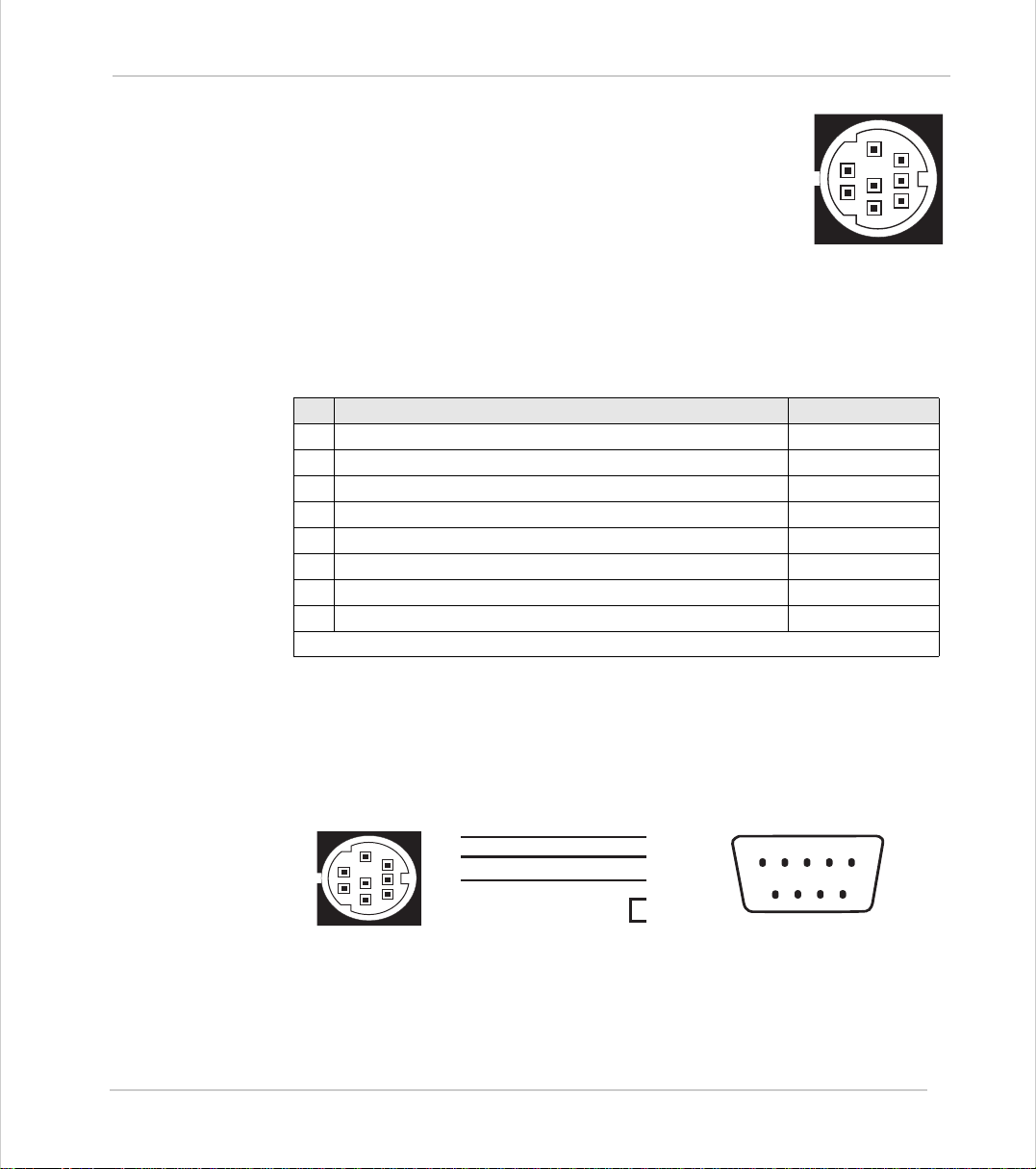
The MC202 features a standard RS-232 serial port for
programming (port 0), and an additional TTL-level output
(port 1) for external communications adaptors such as the
P349 RS-485 Adaptor, or the P435 Serial to Fibre-Optic
Adaptor.
The serial port is the default connection between the Motion Coordinator and
the host PC running Motion Perfect for p rogramming.
MC202 Serial Port Connections
Pin
Function Notes
1
Internal 5v Do not connect
2
Internal 0v Do not connect
3
RS232 Transmit Serial Port 0
4
Ground
5
RS232 Re ceive Serial Port 0
6
External Con trol Output Do not conne ct
7
Externally buffered output Do not connect
8
Externally buffered input Do not connect
Pins 1, 2, 6, 7, and 8 are required to connect to an external fibre-optic adapter.
5
8
2
7
4
1
6
3
Serial Cables
Trio recommend t he use of their pre-made serial cables (product code P350). If
cables need to be made to connect to a PC serial port the following connections
are required:
5
2
4
1
3
5
8
7
4
6
Motion Coordinator to 'AT' style PC with 9pin serial connector
3
2 - Rx
3 - Tx
5 - Gnd
9
8
7
6
7 - RTS
8 - CTS
Hardware Overview 2-7
Motion Coordinator MC202
12345
Page 34
Trio Motion Technology
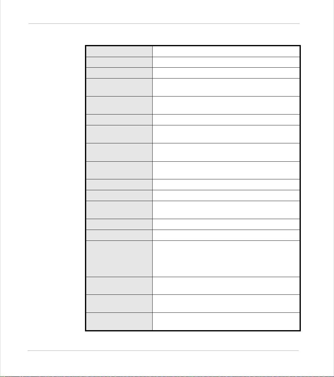
MC202 - Feature Summary
Size 94 mm x 101 mm x 48m m Overall
Weight
Operating Temperature
Control Inputs
Communication Port s
Position Resolution
Inter po lat i o n mo d es
Programming
Speed Resolution
Servo Cycle
Memory
Power Input
Drive Enable Output
+/-10volt DAC Output
200 g
0 - 45 degrees C
Forward Limit, Reverse Limit, Datum Input, Feedhold
Input.
1 RS232 Channel: 96 00 ba ud . TTL ser i al C han ne l 9 600
baud, 1 CAN channel built on to motherboard
32 bit position count
Linear 1-3 axes, circu lar, helical, CAM P rofi le s , sp ee d
control, elec tronic gearbox es.
Multi-tasking Trio BASIC system, maximum 3 simulta -
neous Trio BASIC programs.
32 bit. Speed may be changed at any time. Moves
may be merged.
1ms
128 Kbytes flash user program memory.
24V dc, Class 2 transformer or power source.
18 ... 29V dc at 150mA.
Normally open relay contact rated 24Vdc @ 0.5A..
12 bit resolution, single channel on axis 0 only
Encoder Inputs
Stepper Outputs
Digital Inputs
Digital I/O
2-8 Hardware Overview
Motion Coordinator MC202
2 axes, Differential 5v inputs, 6Mhz maximum edge
rate
*MC202 can gen er ate 150mA at 5v for enco de r pow e r
supplies)
2 axes. Step & Direction: Open collector, 24V @ 50mA
max. 500khz maximum step rate *
4 Opto-isolated 24v inputs, 2 may be used for high
speed registration
4 Opto-isolated bi-directional 24v 250 mA Outputs/
Inputs
Page 35

Motion Coordinator Technical Refe ren ce Ma n ual
Hardware Overview 2-9
Motion Coordinator MC202
Page 36
Trio Motion Technology
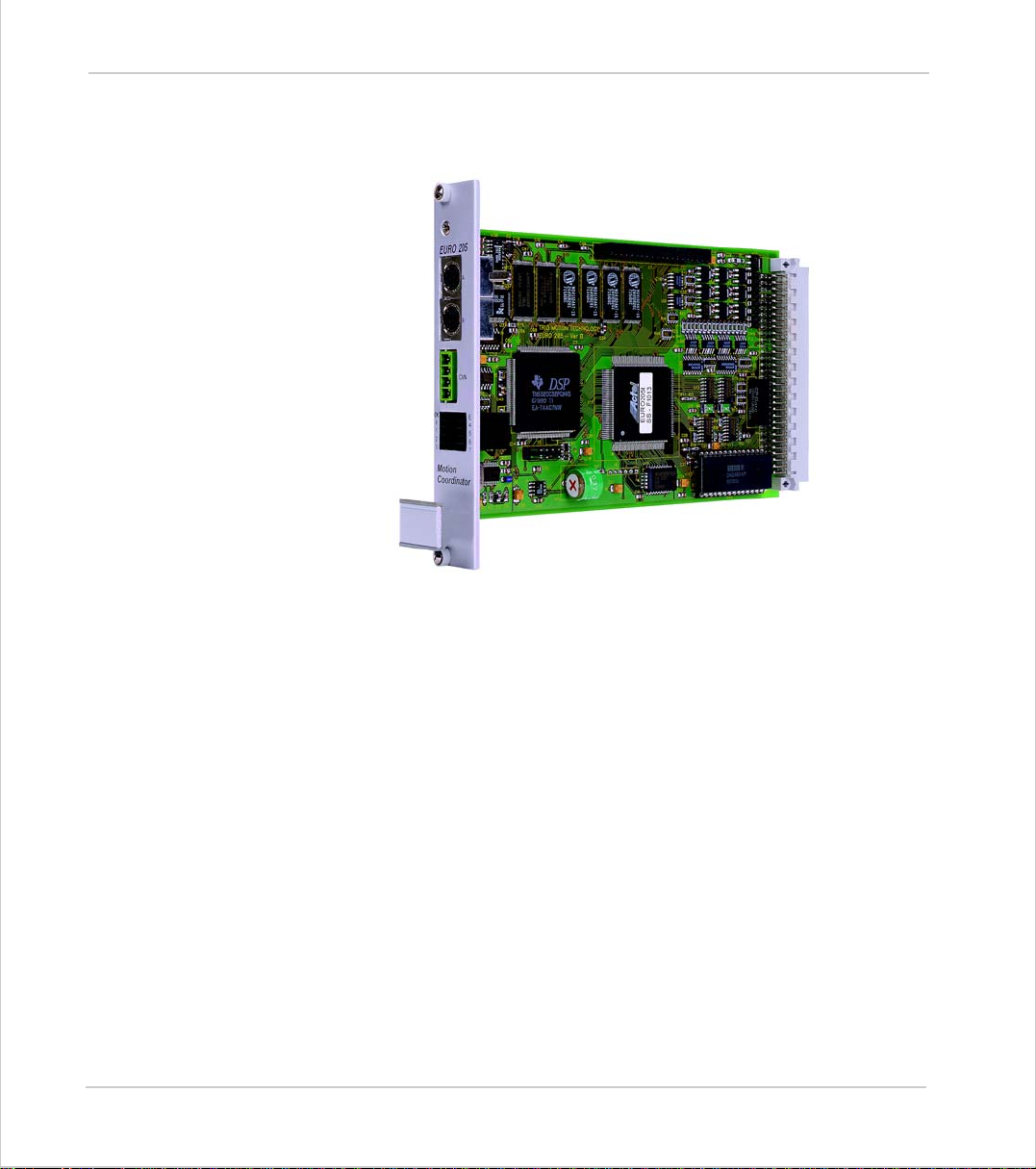
Motion Coordinator Euro205(X )
Overview
Programming
The Motion Coordinator Euro205 and Euro205X are Eurocard stepper/servo positioners with the built-in ability to control up to 4 servo or stepper motors in any
combination. In addition a single Trio Da ughter B oard ma y be fitted to allow the
control of a fifth axis or communications channel. The Euro205(X) is designed to
provide a powerful yet cost-effective control solution for OEM machine builders
who are prepared to mount the unit and provide the power supplies required. It
is designed to be configured and programmed for the application with a Multitasking Trio BASIC using a PC, and then may be set to run “standalone” if an
external computer is not required for the final system. The Multi-tasking version
of Trio BASIC for the Euro205 allow s up to 5 Trio BASIC programs (7 for the
Euro205X) to be run simultaneously on the controller using pre-emptive multitasking.
The Multi-taskin g ability of the Euro 20 5(X) allows parts of a complex application
to be developed, tested and run independently, although the tasks can share
data and motion control hardware.
2-10 Hardwar e Overv iew
Motion Coordina tor Euro20 5(X)
Page 37

Motion Coordinator Technical Refe ren ce Ma n ual
I/O C a pability
Communications
Note
The Euro205(X) has 16 built in 24v inputs and 8 built-in output channels. These
may be used for system interaction or may be defined to be used by the controller for end of travel limits, datuming and feedhold functions if required. 8 status
LEDs are available which can be set to display the status of banks of inputs or
outputs. The Euro205(X) can have up 256 external Input/Output channels and
up to 32 analog input channels connected using DIN rail mounted I/O modules.
These units connect to the built-in CAN channel of the Euro205
The Euro205 has two built in RS-232 ports and 2 further serial channels available
at TTL levels. E xter nal adapte rs are availab le to all ow one of these se rial por ts to
be linked to a full-duplex RS-485 channel and the second to be used to link to
Trio Fibre Optic Network devices. The Euro205X has the RS485 port built-in and
so does not need the adapter.
Serial port pin-out is changed between the Euro205 and Euro205X.
One of the RS-232 ports or the RS485 port may be configured to run the MODBUS
protocol for PLC or HMI interfacing.
If the bu il t-i n CAN channel is not us e d fo r c on ne cti ng I/ O mo dules, it may opt io n -
ally be used for CAN communications.
USB and Profibus daughter boards may be fitted to provide additional communi-
cations options and the Euro205X will accept the Ethernet daughter board.
Axis Configuration
The Euro205X may be purchased as a stepper base card (P151), or a servo base
card (P156). Additional servo or stepper axes may be specified up to the 4 internal axis limit. In addition axes may be added in the field by the entry of “feature
enable codes” into the controller. The codes can be purchased already installed
into a new controller or may be ordered for controllers purchased earlier provided that the serial number is given to Trio. Note that both P151 and P156 have
a serial number label starting P151. P156's have the Feature Enable Code F4
loaded for axis 0 servo.
The gate ar ray at the heart of the E ur o205X des ign has facilities f or 4 s er vo and 4
stepper axes b uilt int o every chip. The “feature enable codes” allo w users to
purchas e only th os e faci lities req uired for t heir co nfig ura tio n. Once enter ed ont o
the controller, the feature enable codes are stored in permanent flash memory.
The feature enable codes are unique for each Euro205X.
The Euro205X features a total of 8 axes in software. Any axes not having a hardware interface can be used as a “virtual” axis.
Hardware Overview 2-11
Motion Coordinator Eur o205(X)
Page 38
Trio Motion Technology
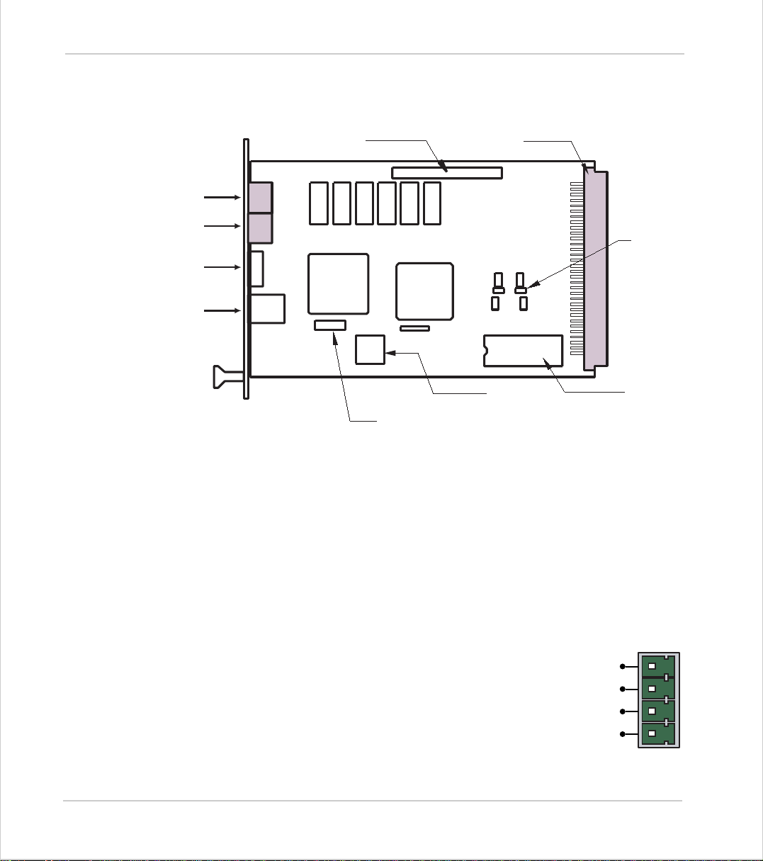
Connections to the Euro 205(X)
Serial Connector A
Serial Connector B
CAN Connector
LED Array
5 volt Power Supply
The minimum connections to the Euro205 are just the 0v and 5v pins. The
Euro205(X) is protected against reverse polarity on these pins. Application of
more than 5.5 volts will permanently damage the Motion Coordinator beyond
economi c r epai r. All the 0v and 5v pins ar e i nt er nally connected together. The 0v
pins are, in addition, internally connected to the AGND pins. The Euro205(X) has
a current consumption of approximately 500mA on the 5v supply. The supply
should be filtered and regulated within 5%.
Daughter Board Connector
X5
X5 and X6 (if fitted) are only
used for production testing !
X6
Rechargable Battery
96 Way Connector
1
1
C B A
M6 and M7
Resettable
Fuses
DAC Socket
Built-in CAN Connector
The Euro205(X) features a built-in CAN channel. This is primarily intended for Input/Output expansion via Trio's P315
and P325 modules. It may be used for other purposes when
I/O expansion is not req uired.
2-12 Hardwar e Overv iew
Motion Coordina tor Euro20 5(X)
0v
CAN_L
SCREEN
CAN_H
Page 39

Motion Coordinator Technical Refe ren ce Ma n ual
Euro 205(X) Backplane Connector
Most connec tio ns to th e Euro205 a nd Eur o205X ar e mad e via the 96 W ay D IN416 12
backplane Connector. Signals marked * are Euro205X only.
C B A
1 5v 5v 5v
2 5v 5v 5v
3 0v 0v 0v
4 IO GND OP13 OP10
5 OP9 OP12 OP15
6 OP8 OP11 OP14
7 IO 24v IN0 / R0* IN1 / R1*
8 IN2 / R2* IN3 / R3* IN4
9 IN5 IN6 IN7
10 IN8 IN9 IN10
11 IN11 IN12 IN13
12 IN14 0v IN15
13 0v DIR2 0v
14 STEP1 STEP2 DIR3
15 DIR0 DIR1 STEP3
16 STEP0 FAULT RESET
17 ENABLE 1 ENABLE (OC) AIN(0)*
18 BOOST1 BOOST0 ENABLE 2
19 BOOST3 BOOST2 Z3- / BOOST3-*
20 A3- / STEP3-* B3- / DIR3-* Z3+ / BOOST3+*
21 A3+ / STEP3+* B3+ / DIR3+* Z2- / BOOST2-*
22 A2- / STEP2-* B2- / DIR2-* Z2+ / BOOST2+*
23 A2+ / STEP2+* B2+ / DIR2+* Z1- / BOOST1-*
24 A1- / STEP1-* B1- / DIR1-* Z1+ / BOOST1+*
25 A1+ / STEP1+* B1+ / DIR1+* Z0- / BOOST0-*
26 A0- / STEP0-* B0- / DIR-* Z0+ / BOOST0+*
27 A0+ / STEP0+* B0+ / DIR+* VOUT0
28 VOUT3 VOUT2 VOUT1
29 +12v +12v +12v
30 AGND AGND AGND
31 -12v -12v -12v
32 Earth Earth Earth
Hardware Overview 2-13
Motion Coordinator Eur o205(X)
Page 40
Trio Motion Technology
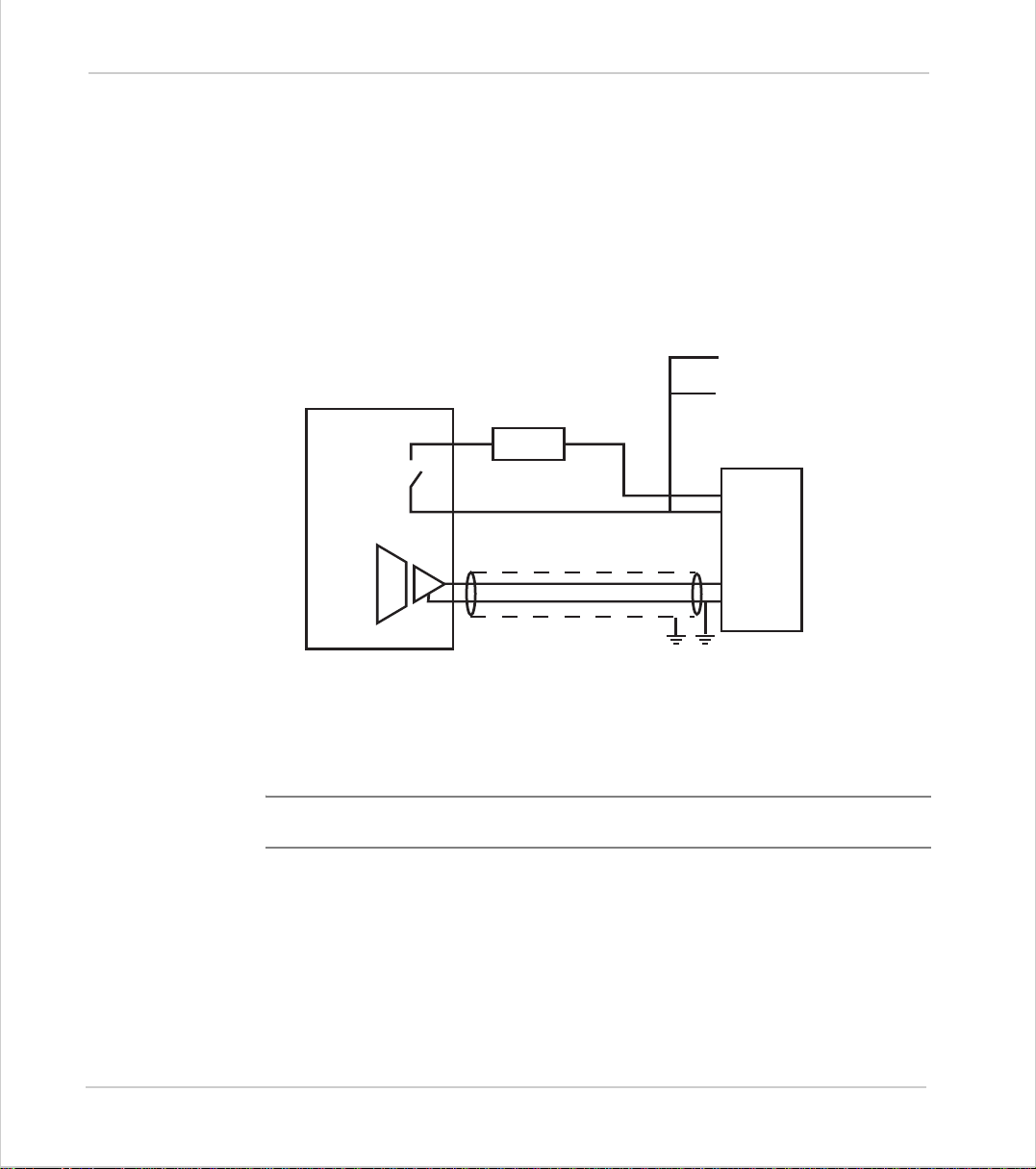
Amplifier Enable (Watchdog) Relay Output
An internal relay contact is used to enable external amplifiers when the controller has powered up correctly and the system and application software is ready.
The amplifier enable is a si ngle pole relay on the Euro205 and a solid-state relay
on the Euro205X with normally open contacts. The enable relay will be open circuit if there is no power on the controller OR a following error exists on a servo
axis OR the user program sets it open with the WDOG=OFF command.
The amplifier enable relay may, for example, be incorporated within a hold-up
circuit or chain that must be intact before a 3-phase power input is made live.
To other axis enables
Amplifier
Enable 1
Amplifier
Enable 2
V+
V -
Trio Controller
24v
0v
0v
Enable
VIN +
VIN -
SERVO
AMPLIFIER
Amplifier Enable Output
Note:
ALL STEPPER AND SERVO A MPLIFIERS MUST BE INHIBITED WHEN THE
AMPLIFIER ENABLE OUTPUT IS O PEN CIR CUIT
2-14 Hardwar e Overv iew
Motion Coordina tor Euro20 5(X)
Page 41
Motion Coordinator Technical Refe ren ce Ma n ual
24v Input Channels
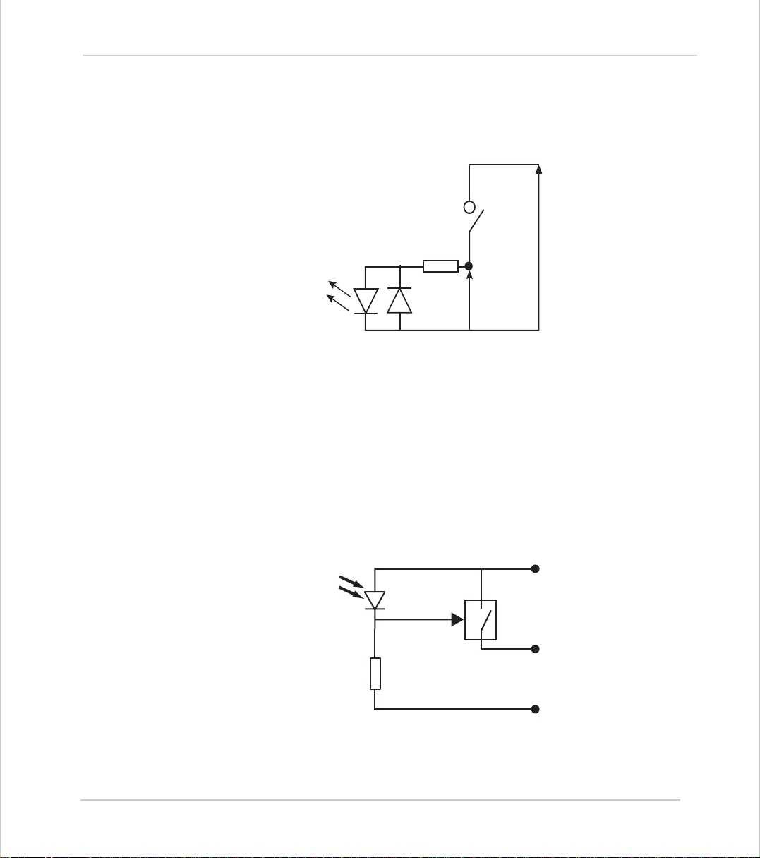
The Motion Coordinator has 16 24v Input channels built into the master unit.
These may be expanded to 256 Inputs by the addition of CAN-16 I/O modules.
24v Output Channels
8 output channels are provided. These channels are labelled 8..15 for compatibility with other Motion Coordinators, but are NOT bi-directional as on some
Motion Coordinat ors. Each channel has a protected 24v sourcing output. The
output circuit has electronic over-current protection a nd t herm al protection
which shuts the output down when the current exceeds 250mA. Care should still
be taken to ensure that the 250 mA limit for the output cir cuit is not exceeded ,
and that the total load for the group of 8 outputs does not exceed 1 amp. Up to
256 further Outputs may be added by the addition of CAN-16I/O modules (P315).
IO 24v
6k8 Ohms
Input Pin
Vin
IO GND
Optical
Output
Control
Signal
IO 24V
Protected
Switch
Output Pin
IO GND
Hardware Overview 2-15
Motion Coordinator Eur o205(X)
Page 42
Trio Motion Technology
Open Collector Stepper Driver Outputs
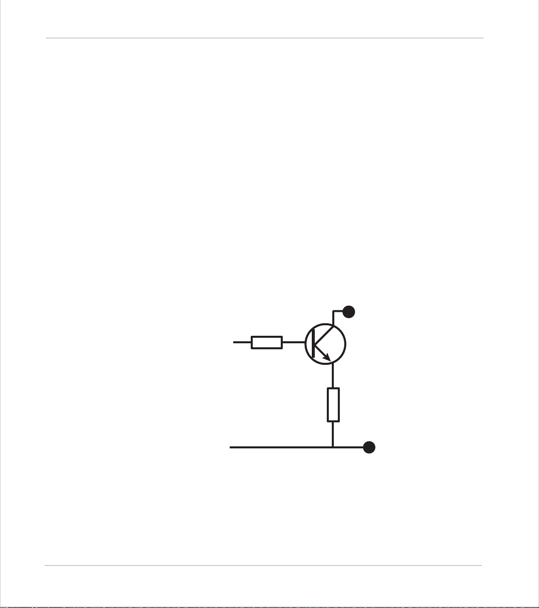
The STEP, DIR, BOOST and ENABLE signals use open-collector outputs. These outputs are NOT opto-isolated from the processor logic. The open-collector outputs
may be pulled up to any voltage in the range 5v..24v as required but a current
limiting resistor MUST be provided externally to the Euro205(X) to limit the current in the output channel. Normally this current limiting resistor is built-in to
the stepper amplifier circuit.
On the Eur o205 the B OOST out put shares a pin wit h the r egistr atio n inpu t for tha t
axis. The BOOST output is normally used in stepper motor systems, and the Registration input is used to capture encoder posi tions. There is not therefore normally a conflict. The BOOST output should not be turned ON on an axis where
the registration input is used otherwise the BOOST outpu t w ill be overloaded.
The BOOST outputs ar e se parate from the registration function on the Euro205X.
The open-collector outputs are protected by 2 resettable fuses. These fuse links
will go high impedance if a total of more than 200mA is passed through a group of
open-collector outputs. M6 protects STEP0, STEP1, STEP2, STEP3, DIR0, DIR1 and
DIR2. M7 protects DIR3, REG(BOOST)0, REG(BOOST)1, REG(BOOST)2,
REG(BOOST)3 and ENABLE. If any outputs are overloaded it is necessary to
remove the power from the circuit in order to res et the fuses.
Open-Collector
Output
Fault and Reset Inputs
Fault is a non-isolated 5 volt input for c o nnection to stepper am plifier f ault outputs. Signals connected to this input should NOT exceed 5volts.
The Reset input can be mome ntari ly conn ected to 0v to reset the Euro205(X).
Signals connected to this pin must not exceed 5 volts.
2-16 Hardwar e Overv iew
Motion Coordina tor Euro20 5(X)
Control Signal
from Logic
M6 / M7 Resettable Fuse
Ov
Page 43

Motion Coordinator Technical Refe ren ce Ma n ual
Registration Inputs
The registration inputs are 24 volt non-isolated inputs referenced to 0v. The
Euro205(X) can be programmed to capture the position of an encoder axis in
hardware when a transition occurs on the registration input.
Differential Encoder Input s
The encoder inputs on the Euro205 and Euro205X are designed to be directly connected to 5 volt differential output encoders. On the Euro205X the encoder
ports are bi-directional so that when axes are set to stepper , th e encoder port for
that axis becomes a Differential Stepper output.
Voltage Outputs
The Euro205(X) can generate 4 +/-10volt analog outputs which are primarily
designed for co ntrolling servo- amplifiers. Euro205 requir es a DAC chip (BurrBrown DAC4814 AP) to be fi tted in t he socke t prov ided, w here as the Eu ro20 5X has
the DAC chip soldered to the PCB. Note that for servo operation the necessary
feature enable codes must have been entered into the Euro205/Euro205X. To use
the voltage outputs the +/-12volt supplies must be present.
Using End of Travel Limit Se nsors
Each axis of the Motion Coor d inator system may have a 24v Input channel allocated to it for the functions:
FORWARD Limit
REVERSE Limit
DATUM Input
FEEDHOLD Input
Switches used for the FORWARD /REVERSE/DATUM/FEEDHOLD inputs mu st be
NORMALLY CLO SED t ype .
Each o f the functions is o ption al and m ay be left unused if not required. Each of
the 4 functi on s are available for each axis and can be assig ned to any in p ut c han nel in the range 0..31. An input can be assigned to more than one function if
desired.
The ax is p ara met ers :
channel s to the fu nctions. The axis parame te rs ar e s e t to -1 if the function is no t
required.
Forward end of travel limit
Reverse end of travel limit
Used in datuming sequence
Used to suspend velocity profiled movements until the
input is released
FWD_IN,REV_IN, DATUM_IN
and
FH_IN
are used to a ssign inpu t
Hardware Overview 2-17
Motion Coordinator Eur o205(X)
Page 44
Trio Motion Technology
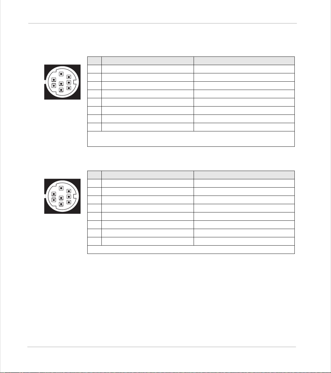
Euro 205 Serial Port Connections
Serial Connector A:
Pin Function (Euro205) Function (Euro205X)
5
2
4
1
3
Serial Connector B:
5
2
4
1
3
1 Internal 5v - P348 supply Internal 5v - P435 supply
8
2 Internal 0v - P348 supply Internal 0v - P435 supply
7
3 RS232 Transmit (Port 0) RS232 Transmit (Port 0)
6
40V 0V
5 RS232 Receive (Port 0) RS232 Receive (Port 0)
6 Out put to P348 Inte r nal 5v
7 Input fr om P348 Output to P435
8 Control to P348 Input from P435
Euro205 only: The external RS485 adapter (P348) is addressed as port #2.
Euro205X only: The external Fibre Optic adapter (P435) is on port #4
Pin Function (Euro205) Function (Euro205X)
1 Internal 5v - P435 supply RS485 Data in A (Port 2)
8
2 Internal 0v - P435 supply RS485 Data in B (Port 2)
7
3 RS232 Transmit (Port 1) RS232 Transmit (Port 1)
6
40V 0V
5 RS232 Receive (Port 1) RS232 Receive (Port 1)
6 +5V output +5V output
7 Output to P435 RS485 Data out Z (Port 2)
8 Input from P435 RS485 Data out Y (Port 2)
Euro205 only: The external Fibre Optic adapter (P435) is on port #4
Network Interconnection
The Euro 205(X) supports Trio’s fibre-optic network with the optional P435 serial
to fibre-optic adaptor connected to the appropriate serial connector.
The software for the network supports interconnection of up to 15 nodes in a
token-ring network format. The nodes may consist of any combination of compatible master controllers and Trio Membrane Keypads.
2-18 Hardwar e Overv iew
Motion Coordina tor Euro20 5(X)
Page 45

Motion Coordinator Technical Refe ren ce Ma n ual
Euro205 - Feature Summary
Size
170 mm x 129 mm Overall (160mm x 100 mm PCB)
25mm deep
Weight
Operat ing Temp. 0 - 45 degree s C
Control In pu t s
170 g
Forward Li mi t, Reverse Limit, Dat um I npu t, Feedhold
Input.
Commun ic ati on Ports
2 RS232 Channels: 1200, 9600,19200,38400 baud.+ 1
RS485 Chann el (us ing adapter )+ 1 Fi bre Opti c Chan nel
(using adap ter)
1 CAN channel built on to motherboard
Position Resolution
Inter po lat i o n mo d es
32 bit position count
linear 1-5 axes, circular, helical, CAM Profiles, speed
control, electronic ge arboxe s.
Programming
Multi-tasking Trio BASIC system, maximum 5 user
tasks.
Speed Resolution
32 bits. Speed may be changed at any time. Moves
may be merged.
Servo Cycle
Memory
Power Input
1ms default value
122 Kbytes battery backed + flash program memory.
500mA at 5 V d.c. (+/-12v at 25mA required for DAC
output)
Amplifier Enable Output
Digital Inputs
Registra tion Inputs 4. One per axis shared with Boost outputs.
Encoder Inputs 4 differential 5v inputs, 6MHz maximu m edge rate
Stepper Outputs
NO relay contact rated 24Vdc @ 0.5A..
16 Opto-isolated 24v inputs
4 Open collector, step and directi on. 5 to 24V. Maximum frequency 500kHz.
Digital Outputs
8 Opto-isolated 24v current sourcing 250 mA outputs
Hardware Overview 2-19
Motion Coordinator Eur o205(X)
Page 46
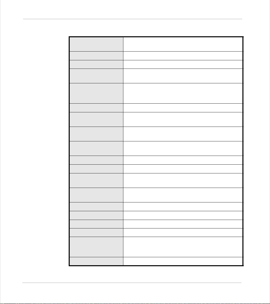
Trio Motion Technology
Euro205X - Feature Summary
Size
170 mm x 129 mm Overall (160mm x 100 mm PCB)
25mm deep
Weight
Operating Temp. 0 - 45 degrees C
Control Inputs
170 g
Forward Li mi t, Reverse Limit, Dat um I npu t, Feedho ld
Input.
Communication Port s
2 RS232 Channels: 9600,19200,38400 baud, 1 RS485
Channel + 1 Fibre Optic Channel (using adapter)
1 CAN channel built on to motherboard
Position Resolution
Inter po lat i o n mo d es
32 bit position count
linear 1-5 axes, circular, helical, CAM Profiles, speed
control, elec tronic gearbox es.
Programming
Multi-ta s king Trio BASIC s ystem, m aximum 7 us er
tasks.
Speed Resolution
32 bits. Speed may be changed at any time. Moves
may be merged.
Servo Cycle
Memory
Power Input
250us, 500us or 1ms (default)
256 Kbytes battery backed + flash program memory.
500mA at 5 V d.c. (+/-12v at 25mA required for DAC
output)
Amplifier Enable Output
Analog Inputs
Digital Inputs
Registration Inputs 4. One per axis shared with inputs 0 to 3.
Encoder Inputs 4 differential 5V inputs, 6MHz maximum edge rate
Stepper Outputs
Digital Outputs
2-20 Hardwar e Overv iew
Motion Coordina tor Euro20 5(X)
NO solid-st ate re lay. Maximim l oad 100m A, maximu m
voltage 29V.
2 x 12 bit 0 to 10V
16 Opto-isolated 24v inputs
4 differ en ti al (5V) or open c oll e ctor (5 to 24V ) st ep &
direction outputs. Maximum frequency 500kHz (OC),
2MHz (Differential).
8 Opto-isolated 24v current sourcing 250 mA outputs
Page 47

Motion Coordinator Technical Refe ren ce Ma n ual
Hardware Overview 2-21
Motion Coordinator Eur o205(X)
Page 48
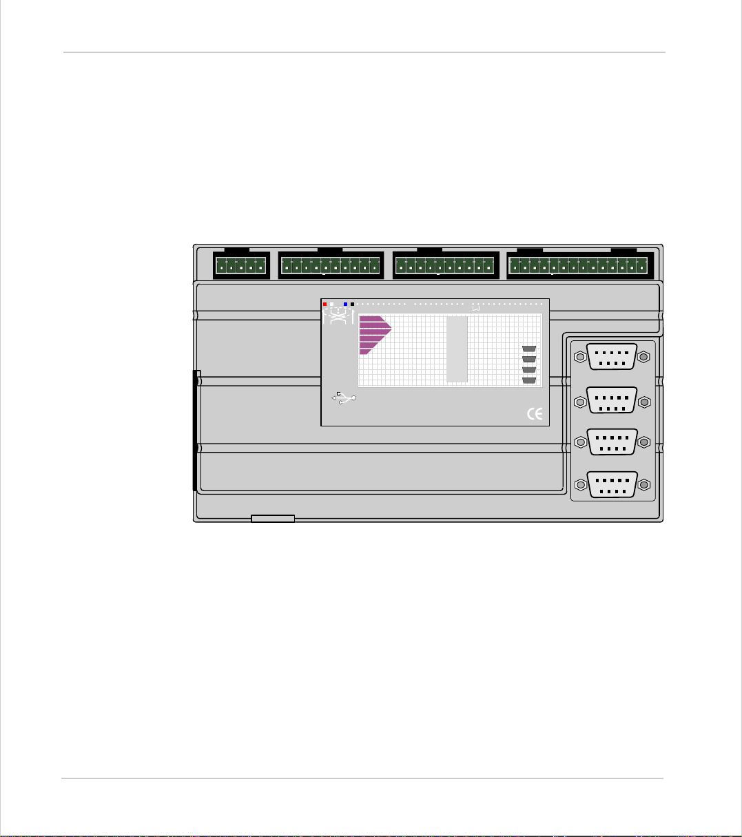
Trio Motion Technology
Motion Coordinator MC206
Overview
The MC206 is based on Trio’s high-performance 32-bit DSP technology and provides up to 4 axes of servo or stepper control, plus a master encoder axis. Trio
uses advanced FPGA techniques to reduce the size and fit 4 axes of stepper and
servo circuitry in a compact D IN-rail mounted package. The housing allow s for a
single daughter board to be mounted internally (with the optional P399 adaptor).
This daughter board may provide additional axis control or communications functions.
0vA012 3 4 5 6 7 0v 24v 8 9
P135
SERIALA
SERIALB
MC206
Motion
Coordinator
10 11 12 13 14 15E-A/AB/BZ/ZV-
OK
STATUS
0
1
2
3
4
5
6
7
V0 V1 V2 V3
Trio
Axis0
Axis1
Axis2
Axis3
5 4 3 2 1
9 8 7 6
5 4 3 2 1
9 8 7 6
5 4 3 2 1
9 8 7 6
5 4 3 2 1
9 8 7 6
User programs are written in Trio’s established multi -tasking Trio BASIC langua ge
using the powerful Motion Perfect development software for the PC. Complex
motion such as cams, gears, linked axes, and interpolation is made easy with the
comprehensive Trio BASIC command set.
I/O C a pability
The MC206 has 16 opto-isolated digital I/O (8 in, 8 bi-directional). A high-speed
hardware registration input is available on each axis for highly accurate control
of print and packaging lines. A single 0..10v opto-isolated analog input is built-in.
The I/O count can be expanded using Trio CANbus digital and analog modules to
provide a further 256 digital 24v I/O channels and 32 +/-10v analog inputs.
2-22 Hardwar e Overv iew
Motion Coordinator MC206
Page 49

Motion Coordinator Technical Refe ren ce Ma n ual
Communications
Removable Storage
The MC206 offers wide communications capability with two RS-232 serial ports,
an RS-485 port, a TTL serial port, a USB port and a CAN channel as standard.
Adapters are available to convert the TTL port to Trio’s fibre-optic network.
RS-232 por t #1, or RS -4 85 p ort #2 may be confi g ur ed to r un t he MO DBUS p r o toco l
for PLC or HMI interfacing.
If the bu il t-i n CAN channel is not us e d fo r c on ne cti ng I/ O mo dules, it may opt io n ally be used for CAN communications.
USB and Profibus daughter boards may be fitted to provide additional communications options.
A memory st i ck used with the MC206 allows a
simple means of transferring programs without
a PC connection. Offering the OEM easy
machine replic at ion and servicing.
The memory stick is ordered separately from
the MC206 if required (order code: P398).
Writing Programs to FlashStick
EPROM(1)
EPROM(2)
Writes programs to FlashStick and clears EPROM request bit on FlashStick
Writes programs to FlashStick and sets EPROM request bit on FlashStick
Checking Programs on FlashStick:
DIR F
Reading Programs from FlashStick:
Programs will be copied on power up or EX from the FlashStick in to the Motion
Coordinator if a FlashStick is inserted and the controller is not locked.
If a FlashSti ck is inser ted and th e cont roll er is unl ocked the act ion ta ken dep ends
on the
the FlashStick:
Lists a directory of FlashStick and prints EPROM request status
POWER_UP
system variable in the controller and the EPROM request bit on
Hardware Overview 2-23
Motion Coordinator MC206
Page 50
Trio Motion Technology
POWER_UP=0
POWER_UP=1
EPROM Request OFF EPRO M Request ON
Programs will be transferred
from the FlashStick to the controller ram on power up.
Programs will be transferred
from the FlashStick to the controller ram on power up.
Programs will be transferred
from the FlashStick to the controller ram on power up. The
programs will then be written t o
internal controller EPROM and
the POWER_UP system variable
set to 1.
Programs will be transferred
from the FlashStick to the controller ram on power up. The
programs will then be written t o
internal controller EPROM.
Notes:
Methods of Use
Axis Configuration
The programs on the FlashStick have auto/manual run settings in the same way
as program s in interna l f lash EPROM do.
In all cases if programs transferred from the FlashStick are set to autorun this
occurs in a similar way
A machinery builder could use a FlashStick with programs loaded and the EPROM
request bit set to install programs on to a series of machines.
If an application update is sent out on a FlashStick to a machinery customer the
EPROM request bit could be left O FF [ U sing
does not do what is required the old program will be copied fro m internal EPROM
when the FlashStick is removed.
The MC206 initiali s es 8 axes in its software: up to four real axes of servo or
stepper are built in, one daughter board axis may optionally be used, an encoder
follower input axis is also built in to every MC206. Any axis of the 8 not used in
hardware can be used as a virtual axis for camming, on-the-fly registration
adjustments, and linking motion.
The MC206 can be a servo or stepper controller by using a “feature enable code”.
All necessary D A C and step per circ uitry is i ns talled and ready for use. The
controller can be supplied with any combination of servo or stepper axes preenabled, and has been designed to allow the user to upgrade at a later date by
entering additional feature enable codes. Up to 4 axes can be enabled on the
MC206.
EPROM(1)
]. In thi s w ay i f the update
2-24 Hardwar e Overv iew
Motion Coordinator MC206
Page 51
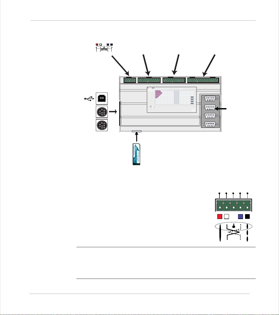
Motion Coordinator Technical Refe ren ce Ma n ual
Connections to the MC206
CANBus
I/O Connector 1
Analog In
Inputs 0-7
I/O Connector 2
24v Power
I/O 8-15
I/O Connector 3
WDOG ï Ref. Encoder
Analog Outputs
USB
SERIAL A
0vA012 3 4 5 6 7 0v 24v 8 9
P135
SERIALA
SERIALB
MC206
Motion
Coordinator
10 11 12 1314 15E-A/AB/BZ/ZV-
OK
STATUS
0
1
2
3
4
5
6
7
Trio
Axis0
Axis1
Axis2
Axis3
V0 V1 V2V3
SERIAL B
Flash Eprom
Memory Stick
5-Way Connector
This is a 5 way 3.81mm pitch connector. The connector is
used both to provide the 24 volt power to the MC206 and
provide connections for I/O expansion via Trio's P315 and
P325 CAN I/O expanders. 24 volts must be provided as this
powers the unit.
This 24 volt input is internally isolated from the I/O 24 volts
and the +/-10v voltage outputs.
5 4 3 2 1
9 8 7 6
5 4 3 2 1
9 8 7 6
5 4 3 2 1
9 8 7 6
5 4 3 2 1
9 8 7 6
Axes 0-3
Encoder Inputs /
Stepper Outputs
H
-
CAN
V+
SHIELD
CAN
L
V-
Note:
The 24v (V+) and 0v (V-) MUST be connected as they power the MC206. The
Shield MUST also be connected as it provides the EMC screen for the Motion
Coordinator. The CAN connections are optional.
Power supply: 24V dc, Class 2 transformer or power source.
Hardware Overview 2-25
Motion Coordinator MC206
Page 52
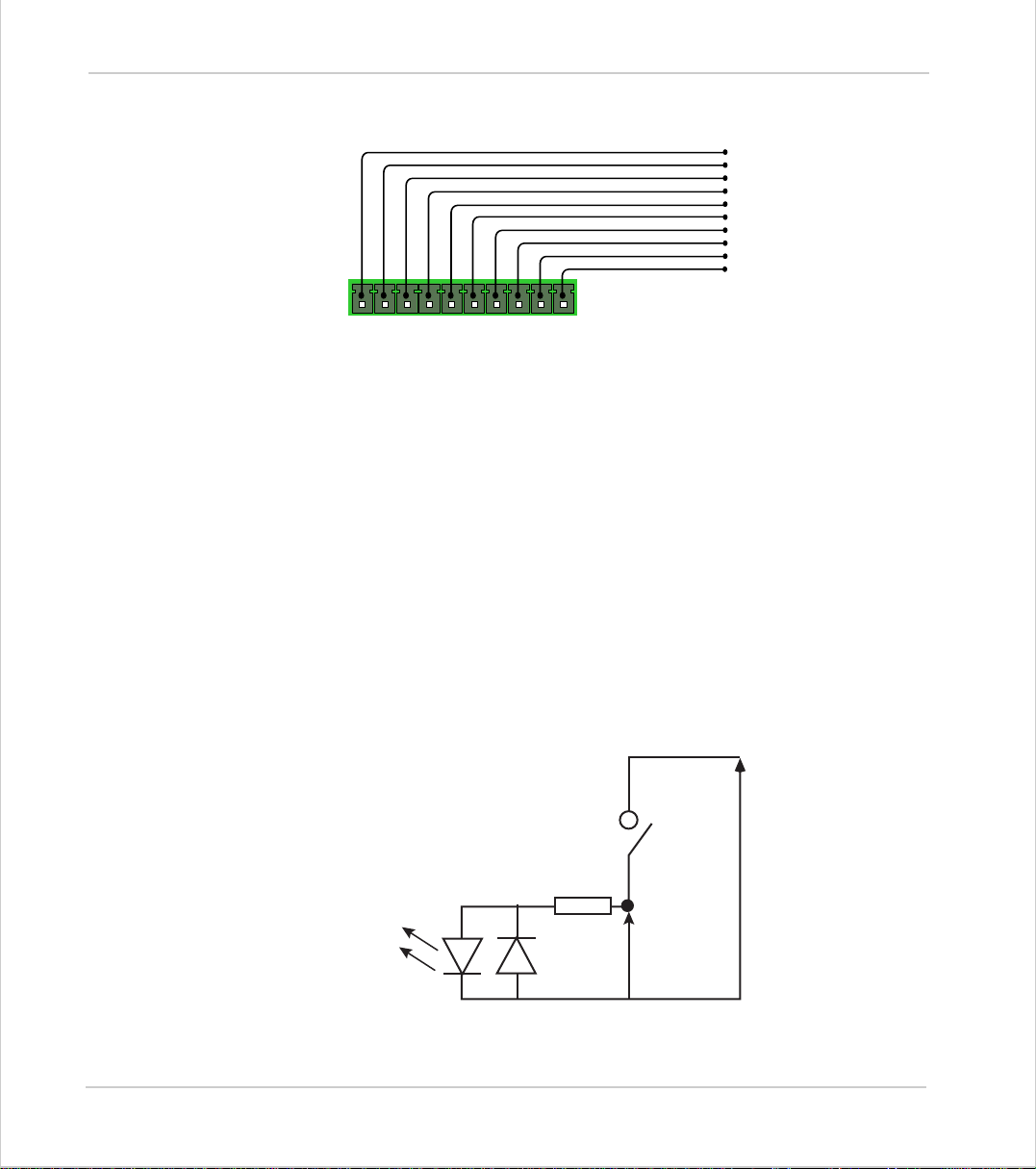
Trio Motion Technology
I/O Connector 1
Analog Input
The MC206 provides a single 0-10v, 10-Bit analog input as standard. The analog
input res o lution is fixed and will return va lues 0..10 23 to the system parameter
AIN0
side the AIN. Power must be applied to the 24v I/O power input in order for the
analog input to function.
It is possible to add further analog inputs via the P325 CAN Analog modules. Each
P325 module provides a further 8 single ended +/- 10v inputs with a 12-Bit resolution.
24v Input Channels
The MC206 has 8 dedicated 24v Input channels and 8 bi-directional 24v I/O channels built into the master unit. A further 256 inputs can be provided by the addition of CAN-16 I/O modules. The dedicated input channels are labelled channels
0..7.
I/O 0v
Analog Input 0-10v
Input 0 / Registration Axis 0
Input 1 / Registration Axis 1
Input 2 / Registration Axis 2
Input 3 / Registration Axis 3
Input 4 / Registration Axis 4
Input 5
Input 6
Input 7
I/O Connector 1
Analog In / Inputs 0-7
. The input works “single ended” and is referenced to the IOGND pin along-
Inputs 0 to 4 can be used as registration inputs for axes 0 to 4 for use with the
REGIST
2-26 Hardwar e Overv iew
Motion Coordinator MC206
command..
IO 24v
6k8 Ohms
Input Pin
Vin
IO GND
MC206 24v Input Channel
Page 53
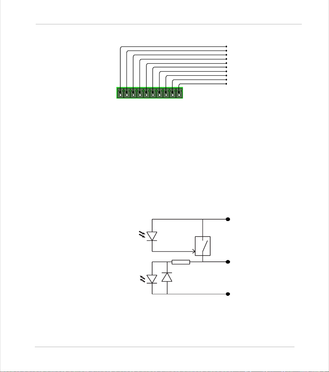
Motion Coordinator Technical Refe ren ce Ma n ual
I/O Connector 2
I/O Power Inputs
The I/O 0 Volts and I/O 24 Volts are used to power the 24 volt inputs and outputs.
The I/O connections are isolated from the module power inputs. The I/O chan-
nels are bi-directional and can be used either as an input or an output.
24v I/O Channels
Input/output channels 8..15 are bi-directional. The inputs have a protected 24v
sourcing o utput connected to the same pin. If the output is unused it may be
used as an input in the program. The input circuitry is the same as on the dedicated inputs. The output circuit has electronic over-current protection and thermal protection which shuts the output down when the current exceeds 250mA.
Care should be taken to ensure that the 250mA limit for the output circuit is not
exceeded, and that the total load for the group of 8 outputs does not exce ed 1
amp.
I/O 0v
I/O 24v
Input / Output Channel 8
Input / Output Channel 9
Input / Output Channel
Input / Output Channel
Input / Output Channel
Input / Output Channel
Input / Output Channel
Input / Output Channel
I/O Connector 2
24v Power / I/O 8-15
10
11
12
13
14
15
Optical
Output
Control
Signal
Optical
Input
Signal
Protected
Switch
6k8
MC206 24v I/O Channel
Hardware Overview 2-27
Motion Coordinator MC206
IO 24V
Input/Output Pin
IO GND
Page 54
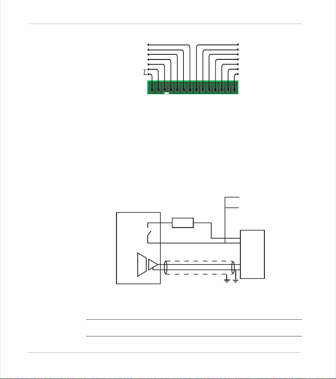
Trio Motion Technology
I/O Connector 3
Amplifier Enable (Watchdog) Relay Output
An internal relay contact is used to enable external amplifiers when the controller has powered up correctly and the system and application software is ready.
The amplifier enable is a single pole relay with a set of normally open contacts.
The enable relay contact wi ll be open circuit if there is no power on the controller OR a following error exists on a servo axis OR the user program sets it open
with the WDOG=OFF command.
The amplifier enable relay may, for example, be incorporated within a hold-up
circuit or chain that must be intact before a 3-phase power input is made live.
Reference Encoder (Axis 4)/B
Reference Encoder (Axis 4) B
Reference Encoder (Axis 4) /A
Reference Encoder (Axis 4) A
Reference Encoder (Axis 4) 0v
Amplifier Enable Relay
(Watchdog)
I/O Connector 3
WDOG / Ref. Enc. / Analog Outputs
Reference Encoder (Axis 4) Z
Reference Encoder (Axis 4) /Z
Analog Outputs 0v (Axes 0-3)
Analog Output - Axis 0
Analog Output - Axis 1
Analog Output - Axis 2
Analog Output - Axis 3
Note:
ALL STEPPER AND SERVO A MPLIFIERS MUST BE INHIBITED WHEN THE
AMPLIFIER ENABLE OUTPUT IS O PEN CIR CUIT
2-28 Hardwar e Overv iew
Motion Coordinator MC206
Amplifier
Enable 1
Amplifier
Enable 2
V+
V -
Trio Controller
24v
0v
Amplifier Enable Output
To other axis enables
0v
Enable
VIN +
VIN -
SERVO
AMPLIFIER
Page 55
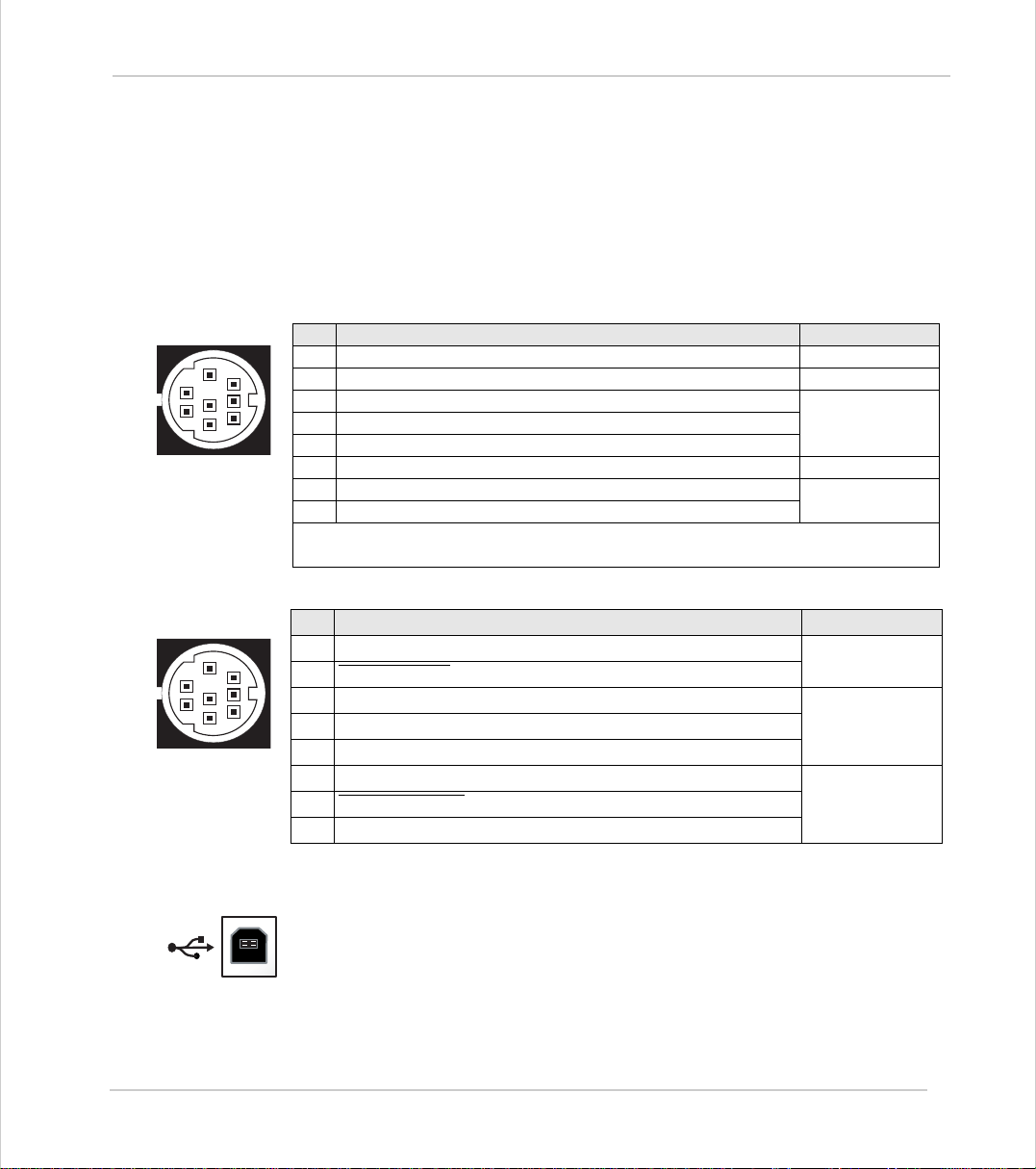
Motion Coordinator Technical Refe ren ce Ma n ual
Reference Encoder Input
A reference encoder - axis 4, provides an encoder input facility for measurement, registration and synchronization functions on conveyors, drums, flying
shears, etc. The encoder port features high speed differential receiver inputs.
MC206 Serial Connections
Serial Connector A:
Pin Function Note
5
2
4
1
3
Serial Connector B:
5
2
4
1
3
1 Internal 5v
2 Internal 0v
8
7
3 RS232 Transmit
6
5 RS232 Receive
6 +5v output
7 Externally buffered output (TTL) For fibre-optic
Note: Port 0 is the de fau lt p r o gr ammi ng p ort fo r co nn ec ti on to the PC running
Motion Perfect.
Pin Function Note
1 RS485 Data In A Serial Port #2
8
2 RS485 Data In
7
3 RS232 Transmit
6
B
4 RS232 GND
5 RS232 Receive
6 Inter nal 5v
7 RS485 Data Out
Z
8 RS485 Data Out Y
Serial Port #04 RS232 GND
adaptor.8 Externally buffered input (TTL)
Serial Port #1
Serial Port #2
USB
Univers al Serial Bus
The USB port provides a high-speed Universal Serial Bus link to a PC or other
device supporting USB.
This port can be used for a high speed connection to Motion P erfect, or to a us e r
program on the PC via Trio’s ActiveX component.
Hardware Overview 2-29
Motion Coordinator MC206
Page 56
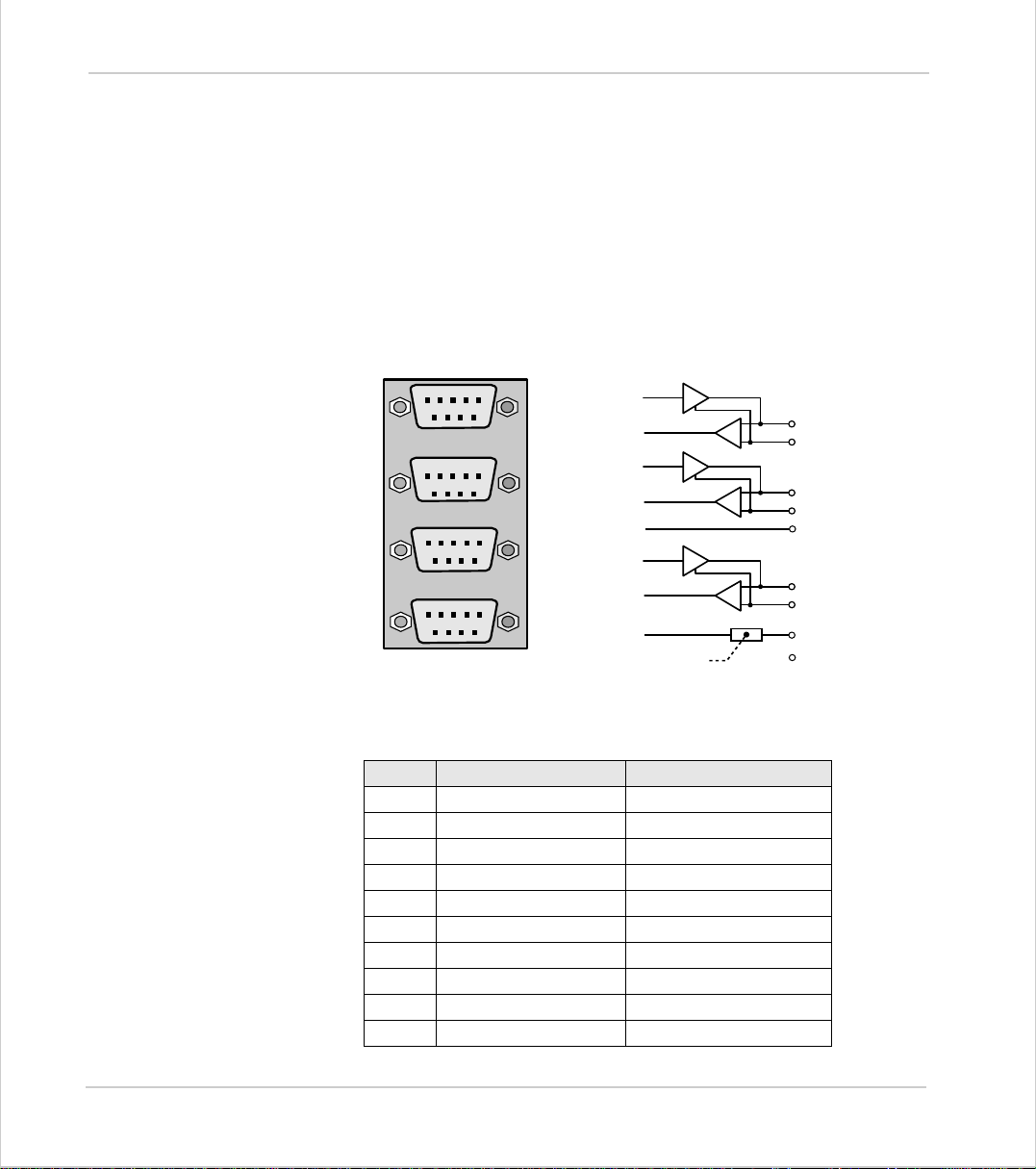
Trio Motion Technology
MC206 - Stepper Outputs / Encoder Inputs
The MC206 controller is designed to support any combination of servo and stepper motors on the standard controll er hardware. Each of t he first four axes (0-3 )
can be enabled as either servo or stepper according to the users requirements.
The function of the 9-pin ‘D’ connectors will be dependant on the specific axis
configuration which has been defined. If the axis is setup as a servo, the connector will provide the encoder input. If the axis is configured as a stepper, the connector provides differential outputs for step/direction and boost/enable signals.
The encoder port also provides a current-limited 5v output capable of powering
most encoders. This simplifies wiring and eliminates external power supplies.
5 4 3 2 1
9 8 7 6
5 4 3 2 1
9 8 7 6
5 4 3 2 1
9 8 7 6
5 4 3 2 1
9 8 7 6
BOOST / ENABLE
Once the axes have been enabled, using the
STEP
DIRECTION
GND
A
B
Z
Current Limit
FEATURE_ENABLE
1
2
3
4
5
6
7
85v
NC
9
function, the controller wi ll e nabl e th e app r op riate har d wa re fo r eac h axis an d the co nn ect o r wil l
function as below.
Pin Servo Axis Stepper Axis
1Enc. A Step +
2Enc. /A Step 3Enc. BDirection +
4 Enc. /B Direc tion 5GND GND
6 Enc. Z Boost +
7 Enc. /Z Boost 85v 5v
9 Not Connected Not Connected
shell Screen Screen
2-30 Hardwar e Overv iew
Motion Coordinator MC206
Page 57

Motion Coordinator Technical Refe ren ce Ma n ual
MC206 - Feature Summary
Size 107mm(H) x 182mm(W) x 53mm(D)
Mounting DIN- rail mounting box
Wei g ht 600 g
Operat ing Temp. 0 - 45 degree s C
Control Inputs Forward Limit, Reverse Limit, Datum Input, Feedhold
Input.
Communica tion Ports (2) RS-232 1200-38400 baud,
(1) RS-485, (1) Serial adapter port,
(1) USB 12Mbit , (1) CAN channel 1 Mbaud
Position Resolution 32 bit position count
Interpolation mode s linear 1-5 axes, circular, helical, CAM Profiles , speed
control, electronic gearboxes.
Programming Multi-tasking Trio BASIC system, maximum 8 tasks.
Speed Resolution 32 bits. Speed/Accel/Decel may be changed at any
time. Moves may be merged for continuous motion.
Servo Cycle 250 µs minimum for all axes, 1 mS default
Memory 256k battery-backed user memory. Entire contents may
be flashed to EPROM.
Memory Stick
(Nexflash MediaStik)
Power Input 24V dc, Class 2 transformer or power source.
Amplifier Enable Output NO relay contact rated 24Vdc at 250mA.
Digital Inputs 8 Opto-isolate d 24V in puts
Digital I/O 8 Opto-isolated 24V current sourcing 250 mA outputs/
Encoder Inputs 5 differential 5V inputs, 6MHz maximum edge rate
Encoder Power Output 5v at 150mA total for 4 encoders plus daughter board
Analog Input Isolate d 10bit 0-10Vdc
Analog Outp uts 4 Isolated 16-bi t +/- 10V
Stepper Outputs 4 Differential Step / Direction outputs 500kHz Max Rate
LED Indicators OK, Status and 8 user programmable I/O status
Connections Screw Terminals, 9-pin D-S hell, 8-pin mini-DIN and USB
Flash memory for program and project transfers to other
MC206 controllers.
18 ... 29V dc at 300mA.
inputs
Hardware Overview 2-31
Motion Coordinator MC206
Page 58
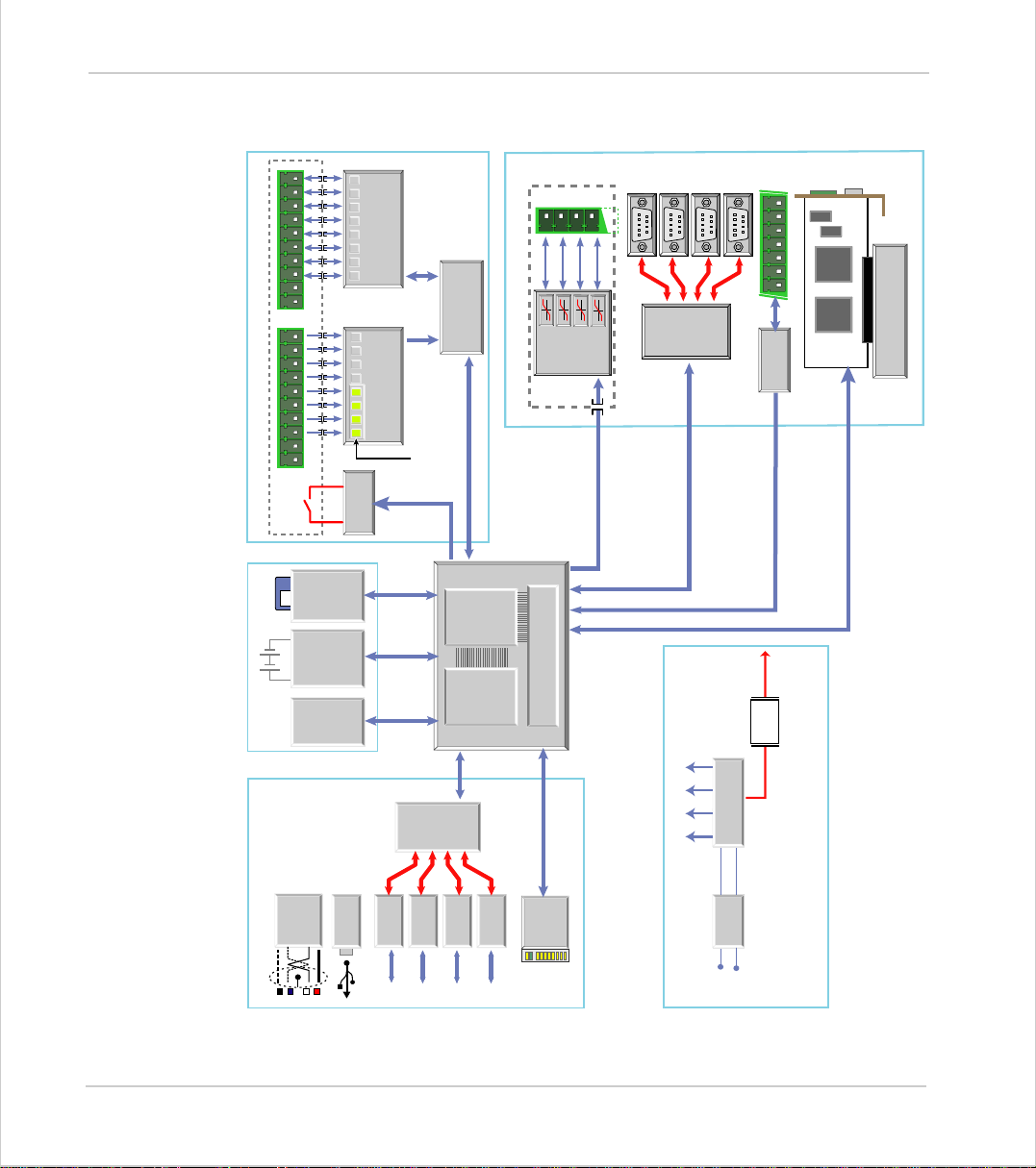
Trio Motion Technology
MC206 - Schematic
I/O SECTION
Isolation
MEMORY
Stick
Flash
Memory
backed
Battery-
256k bytes
Flash
8 M-Bit
EPROM
I/0 8-15
24v opto-isolated
8 9 10 11 14 1512 13
6745
Inputs 0-7
24v opto-isolated
0123
Enable/
Watchdog
RAM
Inputs
Hardware
Registration
I/O Control
FPGA
DSP
32-Bit
Isolation
DAC
Servo
16-Bit
Outputs
MOTION
5M-Bit System SRAM
5 4 3 2 1
9 8 7 6
9 8 7 6
5 4 3 2 1
Inputs /
Encoder
9 8 7 6
5 4 3 2 1
Stepper
Outputs
5 4 3 2 1
9 8 7 6
Current
Encoder
Reference
Limit
Daughter Board
for Encoders and
External 5v Output
connector
Daughter board
CAN
COMMUNICATIONS
2-32 Hardwar e Overv iew
Motion Coordinator MC206
Interface
USB
RS-232
I/F
Serial
RS-232
RS-485
Serial
Adapter Port
Status
Power
Supplies
3V3 +5V +12V-12V
Coordinator MC206
LED’s
POWER SUPPLY
Filter
+24V
Input
Motion
Page 59
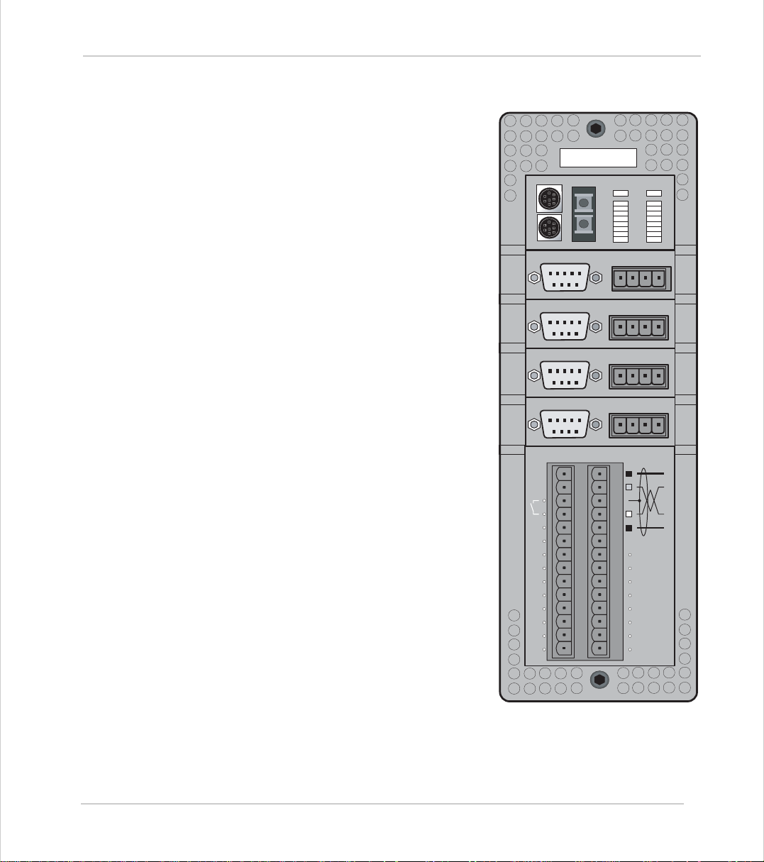
Motion Coordinator Technical Refe ren ce Ma n ual
Moti on Coor di nat or MC216
Overview
The Motion Coordinator MC216 is a powerful
modula r servo control po sitioner with the
ability t o control u p to 16 servo or s tepper
motors in any co mb ination b y the insertion
of “Axis Daughter Boards” to suit the application. I t i s ho us e d in a r ugge d met al chassis
and incorporates all the isolation circuitry
necessary for direct connection to external
equipment in an industrial environment. Filtered power supplies are included so that it
can be powered from the 24V d.c. logic supply present in most industrial cabinets.
It is designed to be configured and programmed for the application using a PC running the Motion Perfect application
software, and then may be set to run “standalone” if an external computer is not
required for the final system.
The Mult i-tasking version of Trio BASIC for
the MC216 allows up to 14 Trio BASIC programs to be run simultaneously o n the controller us ing pre-e mptive mu lt i-tasking .
24v
I 0
I 1
I 2
I 3
I 4
I 5
I 6
I 7
0v
0
1
ENCODER
5 4 3 2 1
9 8 7 6
ENCODER
5 4 3 2 1
9 8 7 6
ENCODER
5 4 3 2 1
9 8 7 6
ENCODER
5 4 3 2 1
9 8 7 6
Trio
NET
OK
0
1
2
3
4
5
6
7
V+ V- R
V+ V- R
V+ V- R
V+ V- R
IO8
IO9
IO10
IO11
IO12
IO13
IO14
IO15
STATUS
8
9
10
11
12
13
14
15
0v
0v
0v
0v
Hardware Overview 2-33
Motion Coordinator MC216
Page 60

Trio Motion Technology
Programming
I/O C a pability
Communications
Axis Po sitioning
Functions
The Multi-tasking ability of the MC216 allows parts of a complex application to be
developed, tested and run independently, although the tasks can share data and
motion control hardware.
The MC216 has 8 built in 24v inputs and 8 bi-directional I/O channels. These may
be used for system interaction or may be defined to be us ed by the controller for
end of travel limits, datuming and feedhold functions if required. Each of the
Input/Output channels has a status LED to make it easy to check them at a
glance. The MC216 can have up 512 external Input/Output channels connected
using DIN rail mounted CAN 16-I/O modules. These units connect to the built-in
CAN channel.
The MC216 has two built in RS-232 ports and has provision for an external duplex
RS-485 channel for simple factory communication systems. The TRIO fibre optic
network system can be fitted as an option.
One of the RS-232 ports may be configured to run the MODBUS protocol for PLC
or HMI interfacing.
If the built-in CAN channel is not us e d for co n necting I/O mo d ule s, i t may optionally be used for CAN communications.
USB and Profibus daughter boards may be fitted to provide additional communications options.
The motion control generation software receives instructio ns to move an axis o r
axes from the Trio BASIC language which is running concurrently on the same
processor. T he motion generation software pr ovides control during operat ion to
ensure smooth, coordinated movements, velocity profiled as specified by the
controlling program. Linear interpolation may be performed in as many axes as
the controller provides, and circular or helical interpolation in any two orthogonal axes. Eac h axi s may run inde p ende nt l y or th ey ma y be li nked in any combination using interpolation, CAM profile or the electronic gearbox facilities.
Consecutive movements may be merged to produce continuous path motion and
the user may program the motion using programmable units of measurement
(e.g. mm, inches, revs etc.). The module may also be programmed to control
only the axis speed. The positioner checks the status of end of travel limit
switche s w hi ch can b e u s ed to cancel mov es i n p r og re s s and alter p rogram execution.
2-34 Hardwar e Overv iew
Motion Coordinator MC216
Page 61
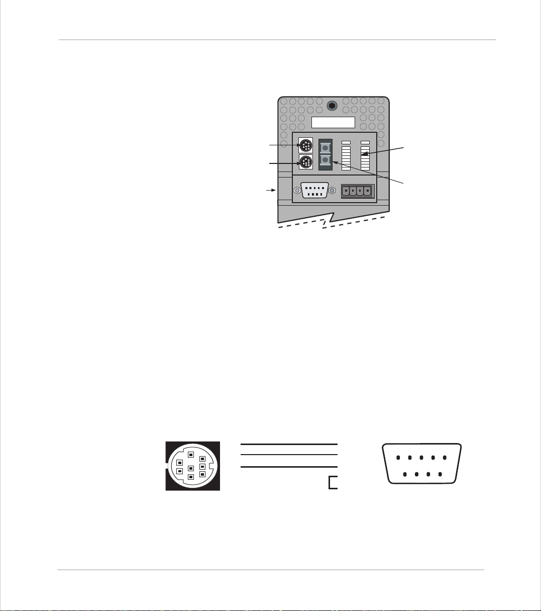
Motion Coordinator Technical Refe ren ce Ma n ual
Connections to the MC216
Serial Port 0
Serial Port 1/2
Axis Daughter Board Slot 0
MC216 upper front panel
MC216 Serial Connections
The MC216 features two serial connectors. Both ports feature a standard RS-232
serial interface. The lower connector (port 1) also has connections for RS-485
multi-drop (addresses as port 2).
0
1
ENCODER
5 4 3 2 1
9 8 7 6
Trio
NET
OK
0
1
2
3
4
5
6
7
V+ V- R
STATUS
8
9
10
11
12
13
14
15
0v
LED Status Display
Fibre-Optic Network
(Optional)
Port 0 is the default connection between the Motion Coordinator and the host
PC running Motion Perfect for p r o gramming. Motion Perfect may also be
connected via USB with the optional (P295) USB Daughter Board
Serial Cables
Trio recommend t he use of their pre-made serial cables (product code P350). If
cables need to be made to connect to a PC serial port the following connections
are required:
5
2
4
1
3
5
8
7
4
6
Motion Coordinator to 'AT' style PC with 9pin serial connector
3
2 - Rx
3 - Tx
5 - Gnd
9
8
7
6
7 - RTS
8 - CTS
Hardware Overview 2-35
Motion Coordinator MC216
12345
Page 62
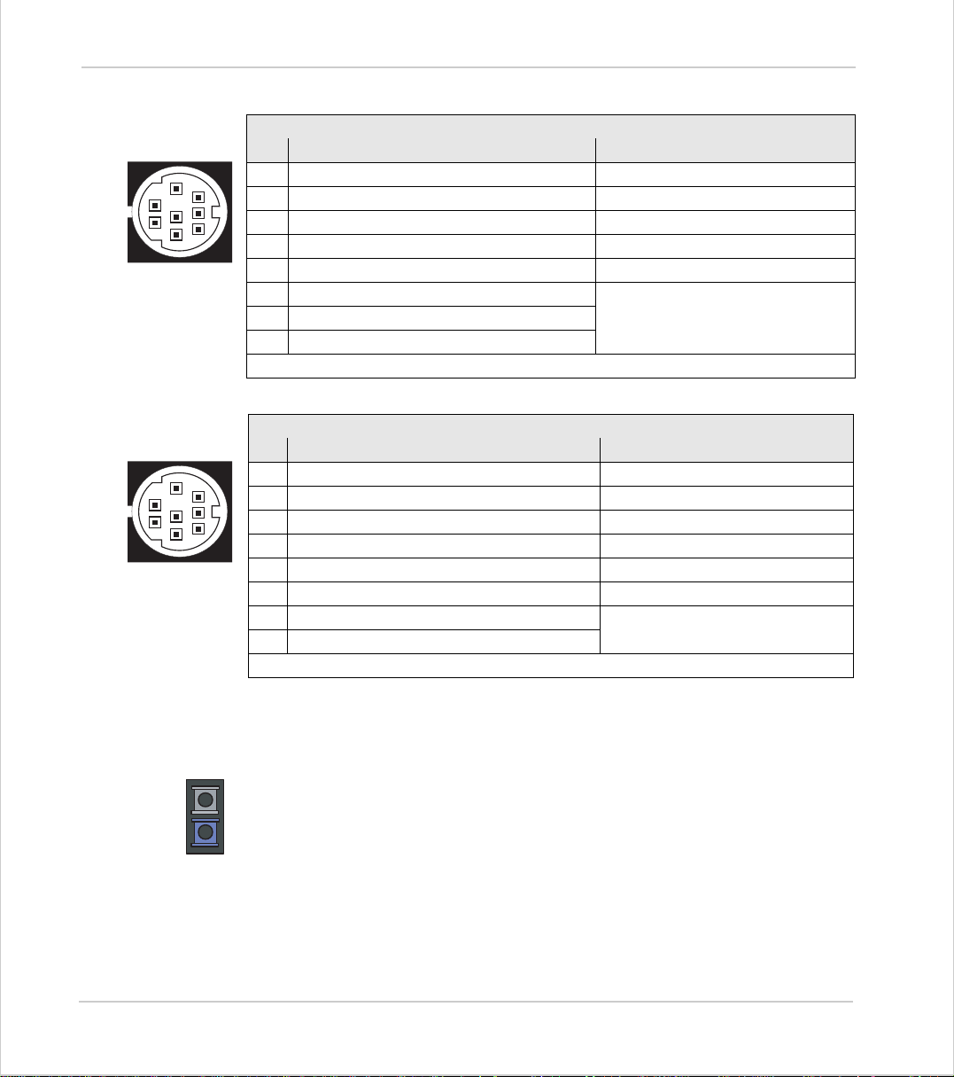
Trio Motion Technology
Serial Connector A:
Serial Connector 0:
Pin Function Notes
5
8
2
7
4
1
6
3
1 Internal 5v
2 Internal 0v
3 RS232 Transmit Serial Port #0
4 RS232 Ground
5 RS23 2 Receive Serial Port #0
6 Externally buffered output
7 Externally buffered input
8 Externally buffered control
On MC216 RS485 can be provided via external adapte r co nn ect ed to p i ns 1,2,6-8
Serial Connector B:
Serial Connector 1
Pin Function Note
5
8
2
7
4
1
6
3
1 Int ernal 5v
2 Int ernal 0v
3 RS232 Transmit Serial Port #1
4 RS232 Ground
5 RS232 Receive Serial Port #1
6 RS232 +5v Output
7 Externally buffered output 2 Serial Port #3 / #4
8 Externally buffered input 2
On the MC216 pins 1,2,7 and 8 can be used to interface a fibre optic adapter.
Serial Port #2
There is no hardware handshake on the serial ports. An XON\XOFF protocol is
used.
Network Interconnection
The optional Fibre-Optic Network connection is designed for communication
between the master modules and membrane keypads on large machines, or small
workgroups of machines.
The software for the network supports interconnection of up to 15 nodes in a
token-ring network format. The nodes may consist of any combination of compatible master controllers and Trio Membrane Keypads.
Note:
Any membrane keypads connected must have software version 2.01 or higher.
2-36 Hardwar e Overv iew
Motion Coordinator MC216
Page 63
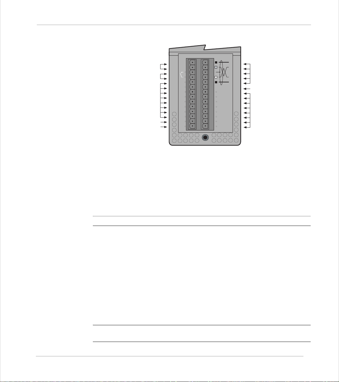
Motion Coordinator Technical Refe ren ce Ma n ual
Unused
Drive Enable
(Watchdog Relay)
24v Input Channels
0 .. 7
Power Input 24v
24v
0v
MC216 lower front panel
24v Power Supply Input
The MC216 is powered entirely via the 24v d.c.supply connecti ons. The unit uses
internal DC-DC converters to generate independent 5v logic supply, the encoder
5v supply and other internal power supplies.
CAN Bus
I0
I1
I2
I3
I4
I5
I6
I7
0v
IO8
IO9
IO10
IO11
IO12
IO13
IO14
IO15
Unused
24v I/O Channels
8 .. 15
24V dc, Class 2 transforme r or power source.
Amplifier Enable (Watchdog) Relay Output
An internal relay contact is used to enable external amplifiers when the controller has powered up correctly and the system and application software is ready.
The amplifier enable is a single pole relay with a set of normally open contacts.
The enable relay contact will be open circuit if there is no power on the controller OR a following erro r exists on a servo axis OR the user p rogram sets it open
with the WDOG=OFF command.
The amplifier enable relay may, for example, be incorporated within a hold-up
circuit or chain that must be intact before a 3-phase power input is made live.
Note:
ALL STEPPER AND SERVO AMPLIFIERS MUS T BE INHIBITED WHEN THE
AMPLIFIER ENABLE OUTPUT IS O PEN CIR CUIT
Hardware Overview 2-37
Motion Coordinator MC216
Page 64
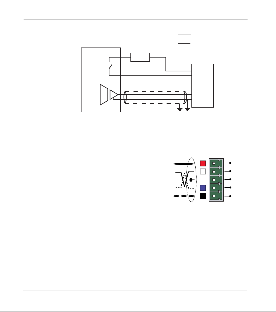
Trio Motion Technology
To other axis enables
Amplifier
Enable 1
Amplifier
Enable 2
V+
V -
Trio Controller
24v
0v
Amplifier Enable Output
CAN Bus:
The MC216 features a built-in CAN channel.
This is primarily intended for Inpu t/Output
expansio n via Trio's P315 and P325 mo dules .
It may be us ed fo r o the r pur po s es wh en I/O
expansion is not required.
0v
Enable
VIN +
VIN -
SERVO
AMPLIFIER
V+
CAN
-
H
SHIELD
CAN
-
L
V-
2-38 Hardwar e Overv iew
Motion Coordinator MC216
Page 65
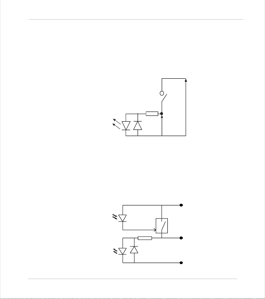
Motion Coordinator Technical Refe ren ce Ma n ual
24v Input Channels
The Motion Coordinator has 16 24v Input channels built into the master unit.
These may be expanded to 256 Inputs by the addition of CAN-16 I/O modules.
All of the 24v input channels have the same circuit although 8 on the master unit
have 24v Output channels connected to the same pin. These bi-directional channels may be used for Input or Output to suit the application. If the channel is to
be used as an Input the output should not be switched on in the program.
24v I/O Channels
Input/output channels 8..15 are bi-directional. The inputs have a protected 24v
sourcing o utput connected to the same pin. If the output is unused it may be
used as an input in the program. The input circuitry is the same as on the dedicated inputs. The output circuit has electronic over-current protection and thermal protection which shuts the output down when the current exceeds 250mA.
IO 24v
6k8 Ohms
Input Pin
Vin
IO GND
Care should be taken to ensure that the 250mA limit for the output circuit is not
exceeded, and that the total load for the group of 8 outputs does not exce ed 1
amp.
Optical
Output
Control
Signal
Optical
Input
Signal
Protected
Switch
6k8
IO 24V
Input/Output Pin
IO GND
Hardware Overview 2-39
Motion Coordinator MC216
Page 66
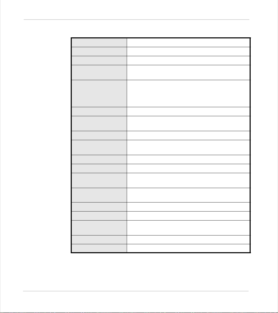
Trio Motion Technology
MC216 - Feature Summary
Size
Weight
Operating Temp.
Control Inputs
Communication Port s
Position Resolution
Inter po lat i o n mo d es
Programming
Speed Resolution
Servo Cycle
Memory
Power Input
262 mm x 68 mm x 198 mm (HxWxD)
0.75 kg
0 - 45 degrees C
Forward Li mi t, Reverse Limit, Dat um I npu t, Feedho ld
Input.
2 RS232 Channels: up to 38400 baud.
RS485 via externally buffered adapter.
1 CAN channel built on to motherboard.
32 bit position count.
Linear 1-16 axes, circular, helical, CAM Profiles,
speed control, electronic gearboxes.
Multi-tasking TRIO BASIC system, maximum 15 tasks.
32 bits. Speed may be changed at any time. Moves
may be merged.
Programmable - Default is 1ms.
500 Kbytes battery backed + flash program memory.
24V dc, transformer or power source.
18..29V dc at 500mA.
Encoder Power Output 5v at 600mA total for 4 encoders via daught er boards.
Amplifier Enable Output
Digital Inputs
Digital Outputs 8 Opto-isolated 24V current sourcing 250 mA out-
LED Indicators OK, Status and 16 I/O status.
Connections Screw Terminals and 2x 8-pin mini-DIN.
2-40 Hardwar e Overv iew
Motion Coordinator MC216
Maximum 150mA per daughter board.
NO relay contact rated 24Vdc @ 0.5A..
8 Opto-isolated 24V inputs.
puts/inputs.
Page 67
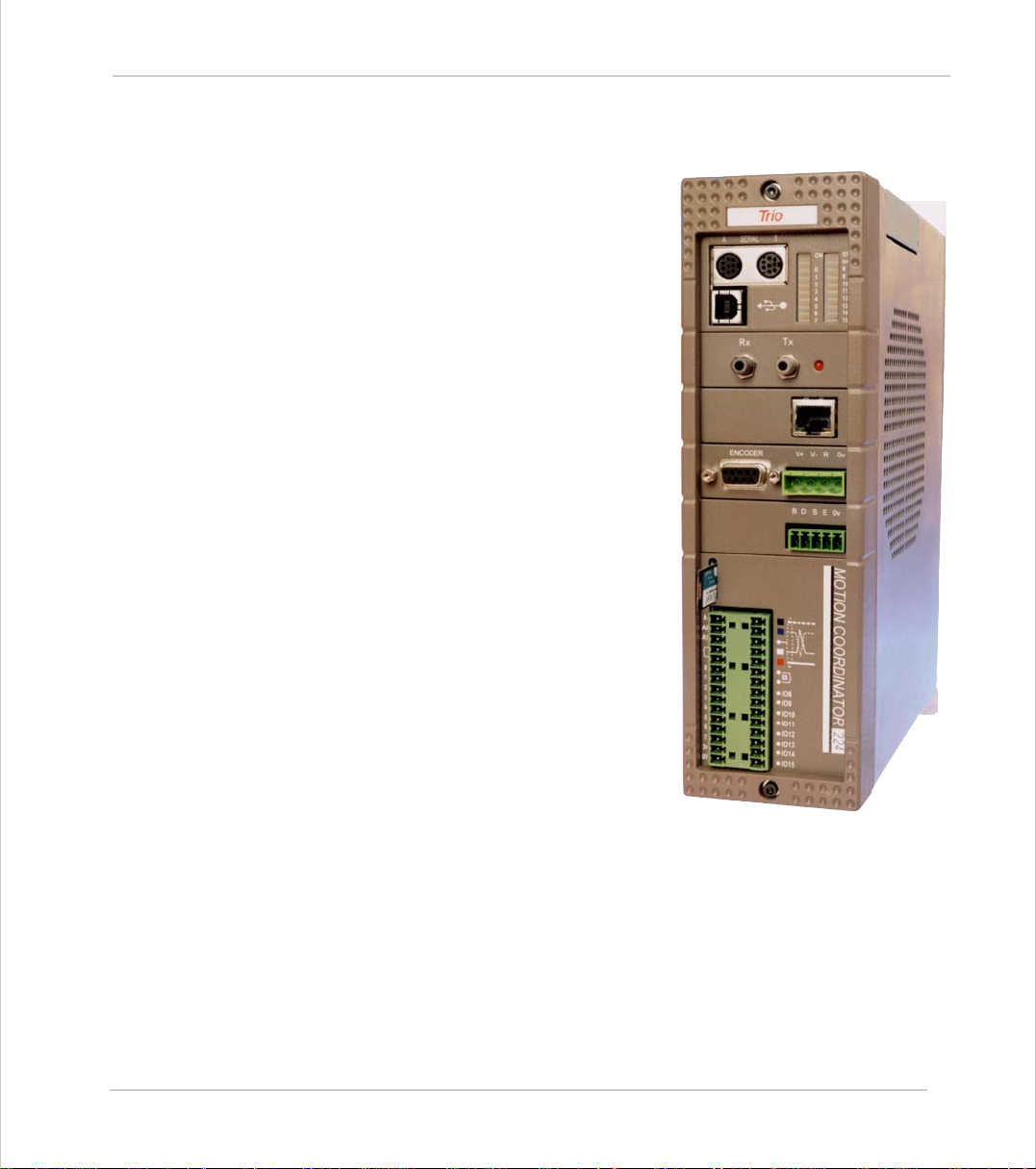
Motion Coordinator Technical Refe ren ce Ma n ual
Moti on Coor di nat or MC224
Overview
The Motion Coordinator MC224 is Trio's most
powerful modular servo control positioner
with the ability to control servo or stepper
motors in any co mb ination b y the insertion
of “Axis Daughter Boards” to suit the application. Up to 24 axes can be controlled by
means of Digital Bus links (e.g. SERCOS) or 16
axes via traditional analog command /
encoder feedback. It is housed in a rugged
metal chassis and incorporates all the isolation circuitry necessary for direct connection
to external equipment in an industrial environment. Filtered power supplies are
included so that it can be powered from the
24V d.c. logic supply present in most industrial cabinets.
It is designed to be configured and programmed for the application using a PC running the Motion Perfect application
software, and then may be set to run “standalone” if an external computer is not
required for the final system.
The Mult i-tasking version of Trio BASIC for
the MC224 allows up to 14 Trio BASIC programs to be run simultaneously o n the controller us ing pre-e mptive mu lt i-tasking .
Hardware Overview 2-41
Motion Coordinator MC224
Page 68

Trio Motion Technology
Programming
I/O C a pability
Communications
Axis Po sitioning
Functions
The Multi-tasking ability of the MC224 allows parts of a complex application to be
developed, tested and run independently, although the tasks can share data and
motion control hardware.
The MC224 has 8 built in 24v inputs and 8 bi-directional I/O channels. These may
be used for system interaction or may be defined to be us ed by the controller for
end of travel limits, datuming and feedhold functions if required. Each of the
Input/Output channels has a status LED to make it easy to check them at a
glance. The MC224 can have up 512 external Input/Output channels connected
using DIN rail mounted CAN 16-I/O modules. These units connect to the built-in
CAN channel.
The MC224 has two built in RS-232 ports and one built in duplex RS-485 channel
for simple factory communication systems. The TRIO fibre optic network system
can be added with an optional adapter cable.
One of the RS-232 ports or the RS485 port may be configured to run the MODBUS
protocol for PLC or HMI interfacing.
If the built-in CAN channel is not us e d for co n necting I/O mo d ule s, i t may optionally be used for CAN communications. e.g. DeviceNet, CANopen etc.
Ethernet, CANbus and Profibus daughter boards may be fitted to provide additional communications options.
The motion control generation software receives instructio ns to move an axis o r
axes from the Trio BASIC language which is running concurrently on the same
processor. T he motion generation software pr ovides control during operat ion to
ensure smooth, coordinated movements with the velocity profiled as specified by
the controlling program. Linear interpolation may be performed in as many axes
as the controller provides, and circular or helical interpolation in any two orthogonal axes. Each axis may run independently or they may be linked in any combination usin g i nterpolation, CA M p rofile or the electronic gearbox facilities.
Consecutive movements may be merged to produce continuous path motion and
the user may program the motion using programmable units of measurement
(e.g. mm, inches, revs etc.). The module may also be programmed to control
only the axis speed. The positioner checks the status of end of travel limit
switche s w hi ch can b e u s ed to cancel mov es i n p r og re s s and alter p rogram execution.
2-42 Hardwar e Overv iew
Motion Coordinator MC224
Page 69
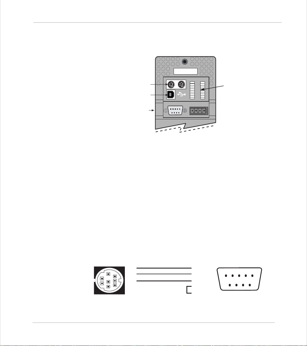
Motion Coordinator Technical Refe ren ce Ma n ual
Connections to the MC224
Serial Ports
USB Port
Axis Daughter Board Slot 0
MC224 upper front panel
MC224 Serial Connections
The MC224 features two serial connectors. Both connectors have a standard RS232 serial inte r fac e. In addition, the left-hand co nn ector (skt A) has co nn ections
for the Fibre-Optic Adapter and skt B contains the RS-485 multi-drop terminals
(addressed as port 2).
SERIAL
A
ENCODER
5 4 3 2 1
9 8 7 6
Trio
B
OK
0
1
2
3
4
5
6
7
V+ V- R
STA
BAT
8
9
10
11
12
13
14
15
0v
LED Status Display
Below the serial port connectors is the built in USB port.
Port 0 is the default connection between the Motion Coordinator and the host
PC running Motion Perfect for programming. As an option, Motion Perfect m ay
be connected via USB.
Serial Cables
Trio recommend t he use of their pre-made serial cables (product code P350). If
cables need to be made to connect to a PC serial port the following connections
are required:
5
2
4
1
3
5
8
7
4
6
Motion Coordinator to 'AT' style PC with 9pin serial connector
3
2 - Rx
3 - Tx
5 - Gnd
9
8
7
6
7 - RTS
8 - CTS
Hardware Overview 2-43
Motion Coordinator MC224
12345
Page 70
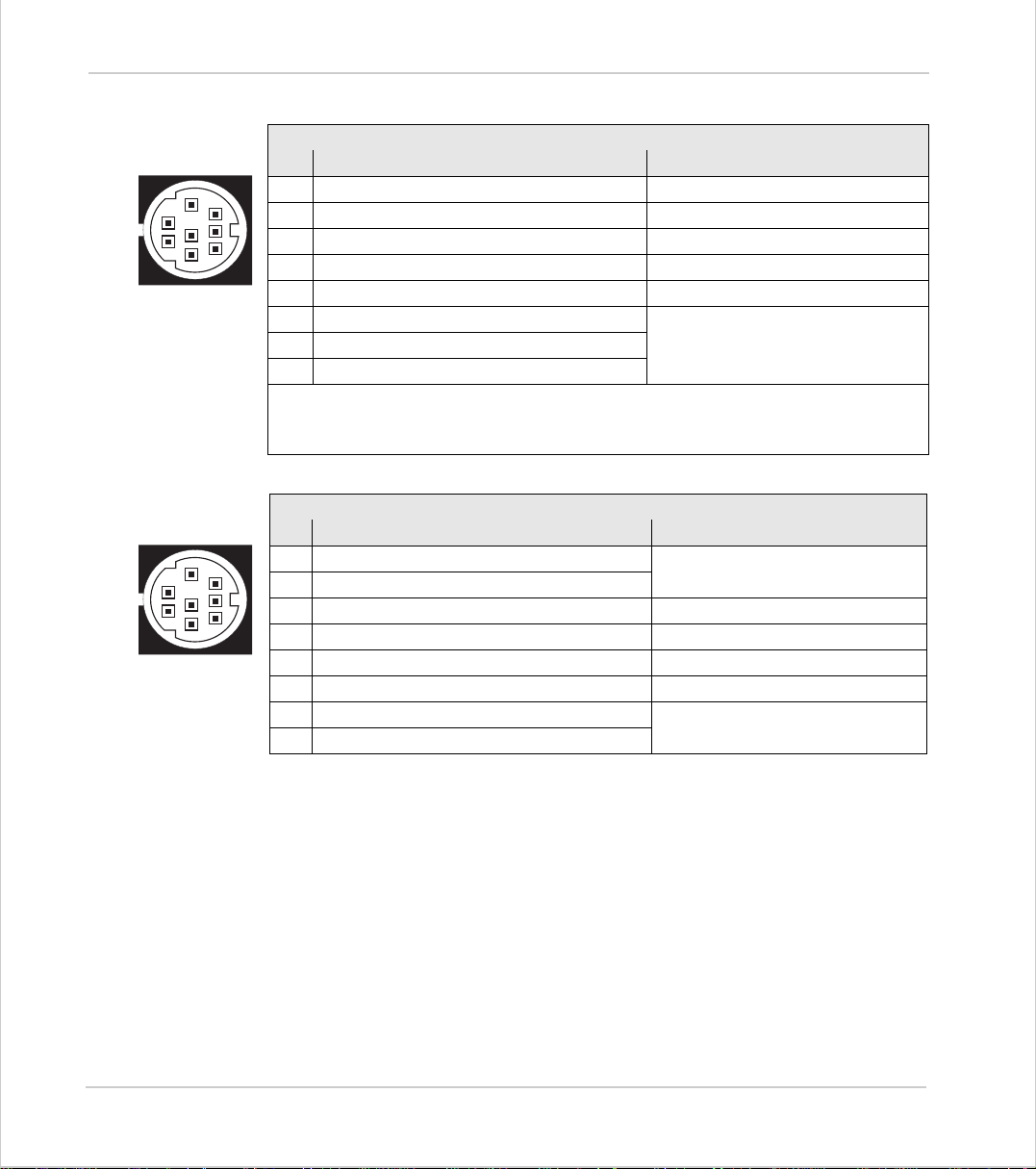
Trio Motion Technology
Serial Connector A:
Serial Connector 0:
Pin Function Notes
5
8
2
7
4
1
6
3
1 Internal 5v
2 Internal 0v
3 RS232 Transmit Serial Port #0
4 RS232 Ground
5 RS23 2 Receive Serial Port #0
6+5V Output
7 Externally buffered output (TTL)
8 Externally buffered input (TTL)
On the MC224 pins 1,2,7 and 8 can be used to interface a fibre optic adapter.
Note: Port 0 is the default programming port for connection to the PC running
Motion Perfect.
Serial Connector B:
Serial Connector 1
Pin Function Note
5
8
2
7
4
1
6
3
1 RS485 Data in A Serial Port #2
2 RS485 Data in B
3 RS232 Transmit Serial Port #1
4 RS232 Ground
5 RS232 Receive Serial Port #1
6+5v Output
7 RS485 Data out Z Serial Port #2
8 RS485 Data out Y
Serial Port #3 / #4
There is no hardware handshake on the serial ports. An XON\XOFF protocol is
used.
Network Interconnection
The optional Fibre-Optic Network connection is designed for communication
between the master modules and membrane keypads on large machines, or small
workgroups of machines.
The software for the network supports interconnection of up to 15 nodes in a
token-ring network format. The nodes may consist of any combination of compatible master controllers and Trio Membrane Keypads.
Note:
Any membrane keypads connected must have software version 2.01 or higher.
2-44 Hardwar e Overv iew
Motion Coordinator MC224
Page 71
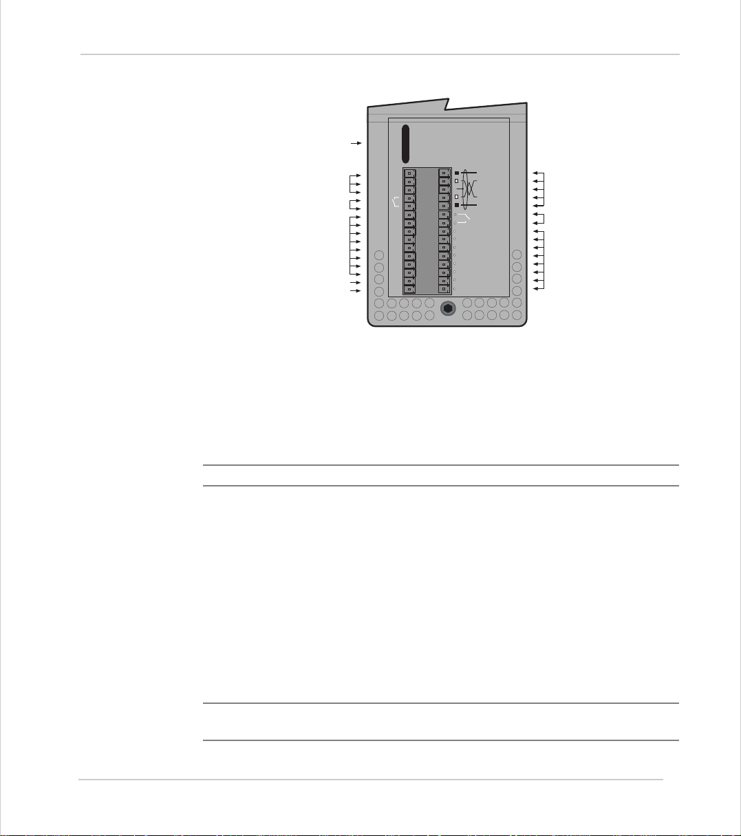
Motion Coordinator Technical Refe ren ce Ma n ual
FlashStick Socket
Analog Inputs 0..1
Drive Enable A
24v Input Channels
0 .. 7
Power Input 24v
A0
A1
I0
I1
I2
I3
I4
I5
I6
I7
24v
MC224 lower front panel
24v Power Supply Input
The MC224 is powered entirely via the 24v d.c.supply connecti ons. The unit uses
internal DC-DC converters to generate independent 5v logic supply, the encoder
5v supply and other internal power supplies.
A-
CAN Bus
B
IO8
IO9
IO10
IO11
IO12
IO13
0v
IO14
IO15
Drive Enable B
24v I/O Channels
8 .. 15
Note:
24V dc, Class 2 transforme r or power source.
Amplifier Enable (Watchdog) Relay Outputs
Two internal relay contacts are available to enable external amplifiers when the
controller has powered up correctly and the system and application software is
ready. The ampl if ier en able s A and B are so li d-s t ate r ela ys wi th an ON re s ist anc e
of 25 ohms at 100mA. The enable relay will be open circuit if there is no power
on the controller OR a following error exists on a servo axis OR the user program
sets it open with the WDOG=OFF command.
The amplifier enable relay may, for example, be incorporated within a hold-up
circuit or chain that must be intact before a 3-phase power input is made live.
Note:
ALL STEPPER AND SERVO AMPLIFIERS MUS T BE INHIBITED WHEN THE
AMPLIFIER ENABLE O UTP UTS ARE OPEN CIRCUIT
Hardware Overview 2-45
Motion Coordinator MC224
Page 72
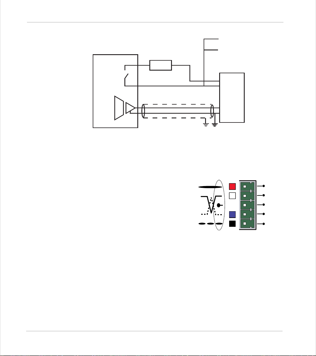
Trio Motion Technology
To other axis enables
Amplifier
Enable 1
Amplifier
Enable 2
V+
V -
Trio Controller
24v
0v
Amplifier Enable Output
CAN Bus:
The MC224 features a built-in CAN channel.
This is primarily intended for Inpu t/Output
expansio n via Trio's P315 and P325 mo dules .
It may be us ed fo r o the r pur po s es wh en I/O
expansion is not required.
The CANbus port is electrically equivalent
to a DeviceNet node.
0v
Enable
VIN +
VIN -
SERVO
AMPLIFIER
V+
CAN
-
H
SHIELD
CAN
-
L
V-
2-46 Hardwar e Overv iew
Motion Coordinator MC224
Page 73
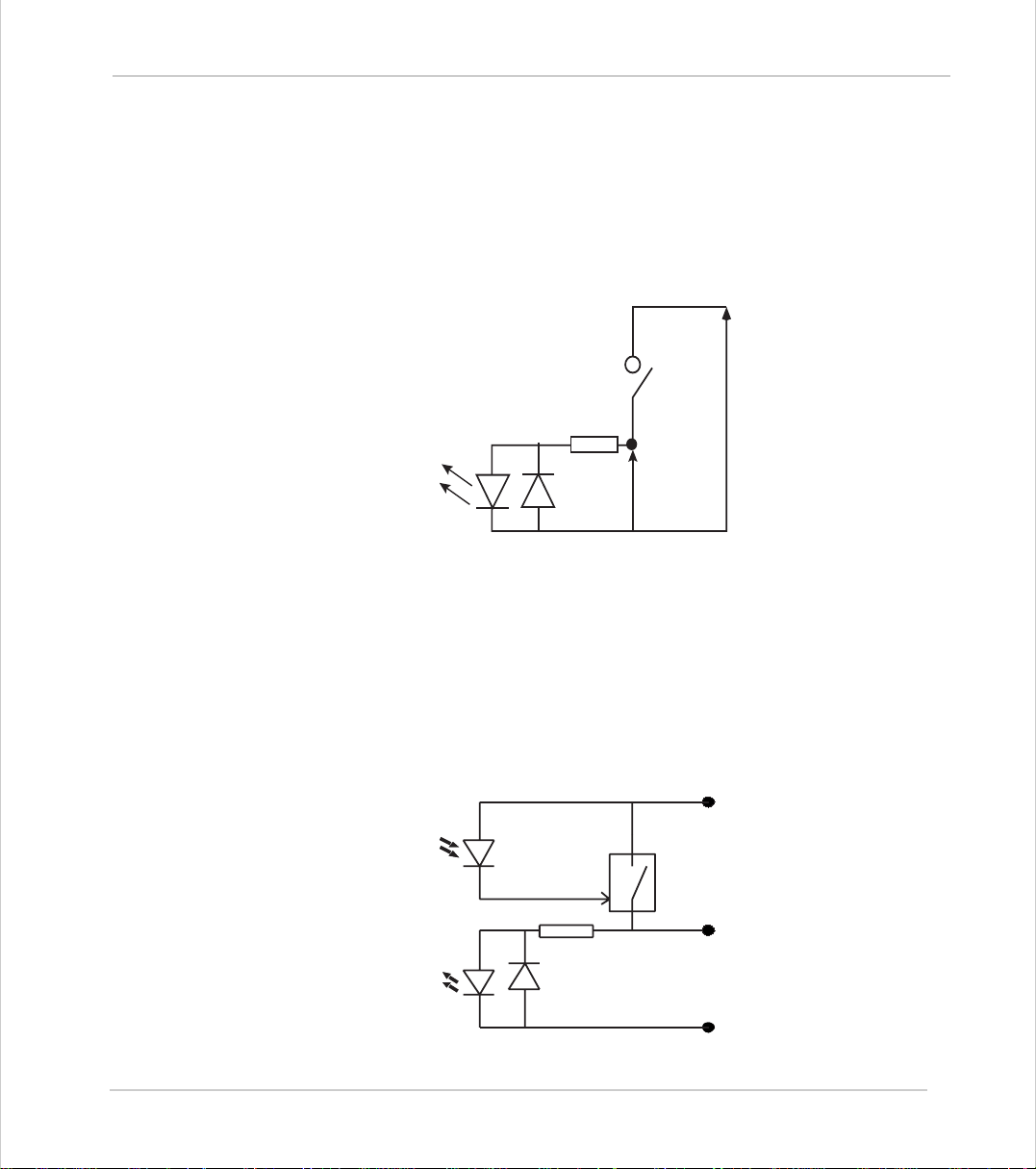
Motion Coordinator Technical Refe ren ce Ma n ual
24v Input Channels
The Motion Coordinator has 16 24v Input channels built into the master unit.
These may be expanded to 256 Inputs by the addition of CAN-16 I/O modules.
All of the 24v input channels have the same circuit although 8 on the master unit
have 24v Output channels connected to the same pin. These bi-directional channels may be used for Input or Output to suit the application. If the channel is to
be used as an Input the output should not be switched on in the program.
24v I/O Channels
Input/output channels 8..15 are bi-directional. The inputs have a protected 24v
sourcing o utput connected to the same pin. If the output is unused it may be
used as an input in the program. The input circuitry is the same as on the dedicated inputs. The output circuit has electronic over-current protection and thermal protection which shuts the output down when the current exceeds 250mA.
IO 24v
6k8 Ohms
Input Pin
Vin
IO GND
Care should be taken to ensure that the 250mA limit for the output circuit is not
exceeded, and that the total load for the group of 8 outputs does not exce ed 1
amp.
Optical
Output
Control
Signal
Optical
Input
Signal
Protected
Switch
6k8
IO 24V
Input/Output Pin
IO GND
Hardware Overview 2-47
Motion Coordinator MC224
Page 74
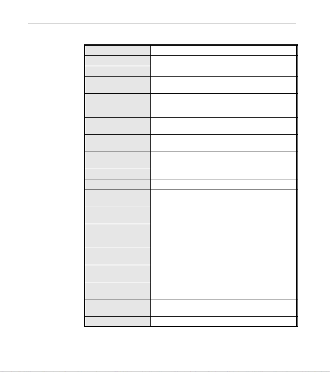
Trio Motion Technology
MC224 - Feature Summary
Size 262 mm x 68 mm x 198 mm (HxWxD)
Weight 0.75 kg
Operating Temp. 0 - 45 degrees C
Control Inputs Forward Limit, Reverse Limit, Datum Input, Feedhold
Communication P orts (2 ) RS232 channels: up to 38400 baud.
Memory 1 Mb yte battery backed RAM. 1 Mbyte TABLE memory.
Memory Stick Socket for plug-in “Nexflash Mediastick”. Used for stor-
Programming Multi-tasking TRIO BASIC system, maximum 14 user
Servo Cycle Programmable: 1 ms, 500 usec or 250 usec.
Position Resolution 32 bit position count.
Speed Resolution 32 bits. Speed may be changed at any time. Moves may
Input.
(1) RS485 channel built in. (1) Ser ial adapter port.
CANbus port. (DeviceNet compatible)
Flash EPROM program storage.
ing programs and/or data.
tasks.
be merged.
Interpolation mode s Linear 1-24 axes, circular, helical , CAM Profiles, speed
Power Input 24V dc, Class 2 transformer or power source.
Encoder Power Output 5v at 600mA total for 4 encoders via daught er boards.
Amplifier Enable Output 2 N.O. solid-state relays rated 24V ac/dc nominal. Maxi-
Digital Inputs 16 Opto-isolated 24V inputs. (Upper 8 inputs shared
Digital Outputs 8 Opto-isolated 24V outputs. Current sourcing
Analog In puts 2 x 1 2-b it 0 to 10V.
2-48 Hardwar e Overv iew
Motion Coordinator MC224
control, electronic gearboxes.
18..29V dc at 450mA ty pical. Max imum: 800 mA + digi tal
output current.
Maximum 150mA per daughter board.
mum load 100mA. Maximum voltage 29V.
with output terminals)
(PNP) 250 mA. (max. 1A per bank of 8)
Page 75

CHAPTER
CHAPTER 0 INSTALLATIO N
Page 76

Page 77
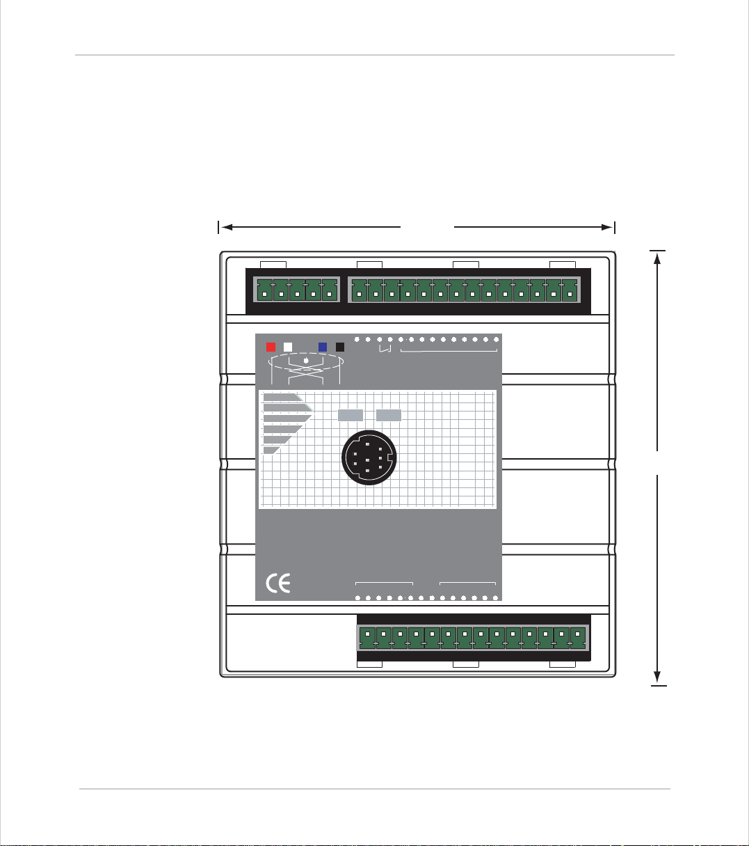
Motion Coordinator Technical Refe ren ce Ma n ual
Motion Coordinator MC20 2
Packaging
The Motion Coordinator MC202 is a DI N rail mo unti ng pro duct. T he mod ule is h eld
by a spring clip on its bottom edge on to the DIN rail. The unit should be mounted
vertically and should not be subjected to mechanical loading. Care should be
taken to ensure that there is a free flow of air vertically around the unit. The
dimensions a r e as shown below.
0vV+V-
94mm
012389101124v
Input/Outputs
Trio
MC202
101mm
Motion
P165
01234
AXIS 0
Coordinator
012345
5v 0v
AXIS 1
5
Including the disconnect terminal, the unit is 48mm deep.
When the serial connector is fitted, around 60mm more depth is required.
Installation 3-3
Motion Coordinator MC202
Page 78

Trio Motion Technology
Connection To Other Trio Products
The MC202 may be connected to other Motion Coordinator modules on the
CAN bus only.
Environmental Considerations
Ensure that the area around the ventilation holes and top of the module are
kept clear. Avoid violent shocks to, or vibration of, the system modules whilst
in use or storage.
3-4 Installation
Motion Coordinator MC202
Page 79
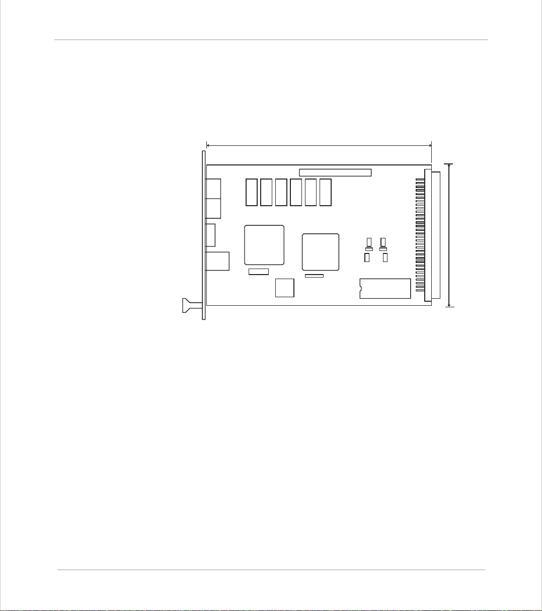
Motion Coordinator Technical Refe ren ce Ma n ual
Motion Coordinator Euro 205
Packaging
The Motion Coordinator Euro 205 is a 3U Eu ro rack mount ing product . The PCB
dimensions are 160mm long x 100mm height. The connectors and front panel
overhang these dimensions.
160mm
C B A
1
100mm
1
Rack Mounting
The Euro205 should be mounted in a shielded metal rack. The unit should be
mounted vertically and should not be subjected to mechanical loading. Care
should be taken to ensure that there is a free flow of air around the unit.
Connection To Other TRIO Products
The Euro205 may be connected to other Motion Coordinators on the CAN bus or
fibre-optic network only.
Environmental Considerations
Avoid violent shocks to, or vibration of, the Euro205 whilst in use or st ora g e.
EMC Considerations
The Euro205 requires external power supplies, a card housing and suitable backplane connections to be supplied and fitted by the machine builder before it can
be used. For th is reason the E ur o205 is not con si d er ed b y Trio to be a pr od uc t fo r
which we can off er qualification to known EMC standards. It is therefore on ly
suitable to be taken into service on machines where the whole system fulfils the
necessary EMC requirements.
Installation 3-5
Motion Coordinator MC202
Page 80
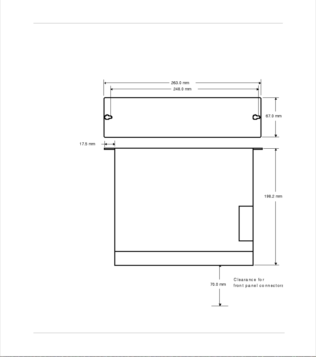
Trio Motion Technology
Motion Coordinator MC21 6
The Motion Coordinator MC2 16 modules are supplied with the same exterior
packag ing which has been specific al ly designed for ease of use a nd flexibil ity
of mounting. The MC216 dimensions are given below.
3-6 Installation
Motion Coordinator MC216
Page 81
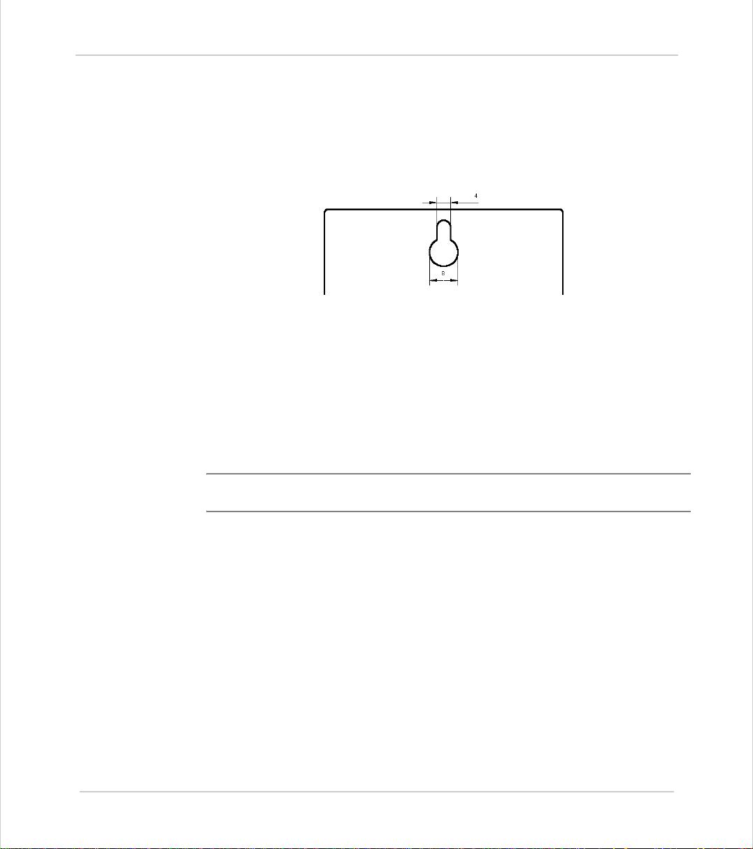
Motion Coordinator Technical Refe ren ce Ma n ual
Bulkhead Mounting
The module may be bulkhead mounted by securing in two locations through the
rear panel of the unit with M4 screws. The unit should be mounted vertically and
should not be subjected to mechanical loading. Care should be taken to ensure
that there is a free flow of air vertically through the unit.
Module Interconnection
Modules to be connected should be mounted on 70mm centres at the same
height. The MC216 should be at the right hand end. After mounting on the bulkhead the interconnection bus cover may be removed by unscrewing the 2 securing screws. The appropriate length of ribbon cable will be supplied ready
assembled and tested by TRIO. With the power off the ribbon cable can be
inserted and the cable locked with the ears on each connector. The power may
then be re-applied and all the interconnection bus covers replaced
Note:
Modules must never be connected or disconnected whilst the power supply is
on.
Environmental Considerations
Ensure tha t th e ar ea aro u nd the ventilation holes a nd top of the module are kept
clear. Avoid violent shocks to, or vibration of, the system modules whilst in use or
storage.
Installation 3-7
Motion Coordinator MC216
Page 82
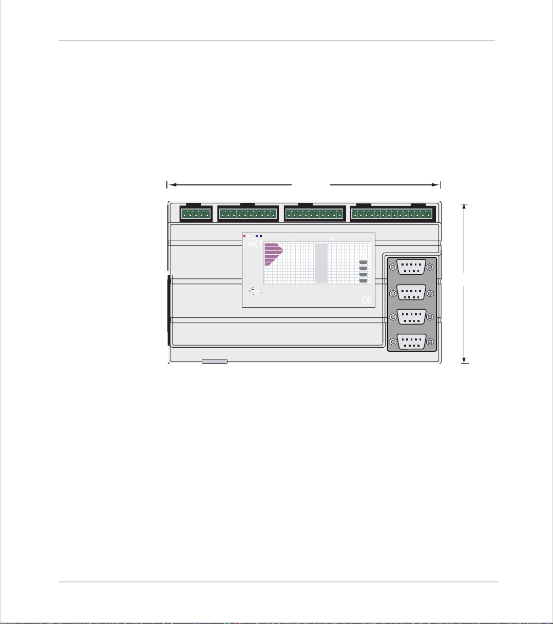
Trio Motion Technology
Motion Coordinator MC20 6
Packaging
The Motion Coordinator MC206 is a DIN rail mounting product. The module is
held by spring clips on its bottom edge on to the DIN rail. The unit should be
mounted vertically and should not be subjected to mechanical loading. Care
should be taken to ensur e th at th er e is a free flo w of air ve rt ic all y arou nd the
unit. The dimensions are as shown below.
180mm
0vA012 3 4 5 6 7 0v 24v 8 9
P135
SERIAL A
SERIAL B
MC206
Motion
Coordinator
10 11 12 13 14 15E-A/AB/BZ/ZV-
OK
STATUS
0
1
2
3
4
5
6
7
V0 V1 V2 V3
Trio
Axis 0
Axis 1
Axis 2
Axis 3
5 4 3 2 1
9 8 7 6
5 4 3 2 1
9 8 7 6
5 4 3 2 1
9 8 7 6
5 4 3 2 1
9 8 7 6
107mm
Including the disconnect terminal, the unit is 48mm deep.
When the serial connector is fitted, around 60mm more depth is required.
Connection To Other TRIO Products
The MC206 may be conne ct ed to ot her Motion Coor d i na tors on the CAN bus or
fibre-optic network only.
Environmental Considerations
Ensure that the area around the ventilation holes and top of the module are
kept clear. Avoid violent shocks to, or vibration of, the system modules whilst
in use or storage.
3-8 Installation
Motion Coordinator MC206
Page 83

Motion Coordinator Technical Refe ren ce Ma n ual
EMC Considerations
Most pieces of electrical equipment will emit noise either by radiated emissions
or conduc ted e mi ssi o ns al on g th e co nnecting w ires . T hi s no is e can cause interf er ence with other equipment near by which could lead to that equipment malfunctioning. These sort of problems can usually be avoided by careful wiring and
following a few basic rules.
1) Mount noise generators such as contactors, solenoid coils and relays as far away
as possible from the modules.
2) Where possible use solid-state contactors and relays.
3) Fit suppressors across coils and contacts.
4) R oute heavy current power and motor cables away from sign al and data cables.
5) Ensure all the modules have a secure earth connection.
6) Where scr eened cables are use d terminate the screen with a 360 de gree termination, if possible, rather than a “pig-tail” and connect both ends of the screen to
ground.
The screening should be continuous, even where the cable passes through a cabinet wall or connector.
These are just very genera l guidel ines and for more specific ad vice on s p ecific
controllers, see the installation requirements later in this chapter. The consideration of E M C im pli cations is now mo re i mpo rt ant th an ever sinc e the introduc ti o n
of the EC EMC directive which makes it a legal requirement for the supplier of a
product to the end customer to ensure that it does not cause interference with
other eq uipment and that it is not itself susceptib le to interf erence from other
equipment.
Background to EMC Directive
Since 1st January 1996 all suppliers of electrical equipment to end users must
ensure that their product complies with the 89/336/EEC Electromagnetic Compatibility directive. The essential protection requirements of this directive are:
1) Equipment must be constructed to ensure that any electromagnetic disturbance
it generates allows radio and telecommunications equipment and other apparat us
to function as intended.
2) Equipment must be constructed with an inherent level of immunity to externally
generated electromagnetic disturbances.
Installation 3-9
EMC Considerati on s
Page 84

Trio Motion Technology
Suppliers of equipment that falls within the scope of this directive must show
“due diligence” in ensuring compliance. Trio has achieved this by having products that i t co nsi d er s to be withi n th e s cop e o f th e d irec t i ve tes ted at an independent test house.
As products comply with the general protection requirements of the directive
they can be marked with the CE mark to show compliance with this and any
other relevant directives. At the time of writing th is manual the only applicable directive is the EMC directive. The low voltage directive (LVD) which took
effect from 1st January 1997 does not apply to current Trio products as they
are all powered from 24V which is below the voltage range that the LVD
applies to.
Just because a system is made up of CE marked products does not necessarily
mean that the completed system is compliant. The components in the system
must be connected together as specified by the manufacturer and even then it
is possible for some interact ion between different compo nents to cause problems bu t obviously it is a step in the right direction i f a ll compon ents are CE
marked.
Testing Standards
For the purposes of testing a typical system configuration had to be chosen
becaus e of th e modular nature of the Motion Coordinator products. Full
details of this and copies of test certificates can be supplied by Trio if
required. For each typical system configuration testing was carried out to the
following standards:
3-10 Installation
EMC Con s id e r ations
Emissions - BS EN55022:1995 or BS EN50081-1:1992
(depending on the particular product.)
Note that both standards specify the same limits for radiated emissions which
is the only applicable part of the standards to Trio products. Most products
conform to the Class A limits but some products, such as the range of membrane keypads, are within Class B limits.
Immunity - BS EN50082-2:1995.
This standar d se ts li mi ts f o r i mmu ni ty i n an ind ust ri al en vi ron men t an d i s a fa r
more ri gorous test than part 1 of the standard.
Page 85

Motion Coordinator Technical Refe ren ce Ma n ual
Install atio n Requi remen ts to Ens ure Conf orma nc e
Motion Coordinator MC202
When the Trio products are tested they are wired in a typical system configuration. The wiring practices used in this test sy stem must be followed to ensure the
Trio products are compliant within the completed system.
A summary of the guidelines follows:
1) The MC202 modules should be earthed via its EARTH connection of the CAN connector.
2) If any IO lines are not to be used they should be left unconnected rather than
being taken to a terminal block, for example, as lengths of unterminated cable
hanging fro m an IO port can act as an antenna for noise.
3) Screened cable s shou ld be used for encoder, stepper and registr atio n input feedback signals and for the demand voltage from the controller to the servo amplifier if relevant. The demand voltage wiring must be less than 1m long and
preferably as short as possible. The screen should be connected to earth at both
ends. Termination of the screen should be made in a 360 degree connection to a
metallised connector shell. I f the connection is to a screw terminal e.g. demand
voltage or registration input the screen can be terminate d with a short pig-t ail to
earth.
4) Connection to the serial ports should be made with a Tr io supplied cable. When a
Motion Coordinator is not connected to a PC the serial cable must be removed as
it will act as an antenna for electrical noise if it is left unterm inated.
5) The MC202 shoul d not be handled whilst the 24 volt powe r is connected.
As well as following these guidelines, any installation instructions for other products in the system must be observed.
Motion Coordinator Euro 205
The Euro205 should be mounted in a screened metal card cage. The power supplies should be generated by regulated filtered supplies.
The following requirements should also be adhered to:
1) The Euro205's front panel should be earthed.
2) If any IO lines are not to be used they should be left unconnected rather than
being taken to a terminal block, for example, as lengths of unterminated cable
hanging fro m an IO port can act as an antenna for noise.
Installation 3-11
EMC Considerati on s
Page 86

Trio Motion Technology
3) Screened cable s shou ld be used for encoder, stepper and registration input
feedback signals and for the d emand voltag e from the contr oller to the servo
amplifier if relevant. The demand voltage wiring must be less than 1m long
and preferably as short as possible. The screen should be connec ted to earth
at both ends. Termination of the screen should be made in a 360 degree connection to a metallised connector shell. If the connection is to a screw terminal e.g. demand voltage or registration input the screen can be terminated
with a short pig-tail to earth.
4) Connection to the serial ports should be made with a Trio supplied cable.
When a Motion Coordinator is not connected to a PC the serial cable must be
removed as it will ac t as an antenna for electrical noise if it is left unte rminated.
The Euro205 should not be handled whilst the power is connected.
As well as following these guidelines, any installation instructions for other
products in the system must be observe
Motion Coordinator MC206
When the Trio products are tested they are wired in a typical system configuration. The wiring practices used in this test system must be followed to
ensure the Trio produc ts are complian t within the comple ted system.
A summary of the guidelines follows:
3-12 Installation
EMC Con s id e r ations
1) The MC206 modules should be earthed via its EARTH connection of the CAN
connector.
2) If any IO lines are not to be used they should be left unconnected rather than
being taken to a te rminal block, for e xample, as len gths of un terminate d cable
hanging fro m an IO port can act as an antenna for noise.
3) Screened cable s shou ld be used for encoder, stepper and registration input
feedback signals and for the d emand voltag e from the contr oller to the servo
amplifier if relevant. The demand voltage wiring must be less than 1m long
and preferably as short as possible. The screen should be connec ted to earth
at both ends. Termination of the screen should be made in a 360 degree connection to a metallised connector shell. If the connection is to a screw terminal e.g. demand voltage or registration input the screen can be terminated
with a short pig-tail to earth.
4) Connection to the serial ports should be made with a Trio supplied cable.
When a Motion Coordinator is not connected to a PC the serial cable must be
removed as it will ac t as an antenna for electrical noise if it is left unte rminated.
Page 87

Motion Coordinator Technical Refe ren ce Ma n ual
5) The MC206 shoul d not be handled whilst the 24 volt powe r is connected.
As well as following these guidelines, any installation instructions for other products in the system must be observed.
Motion Coordinator MC216
When the Trio products are tested they are wired in a typical system configuration. The wiring practices used in this test sy stem must be followed to ensure the
Trio products are compliant within the completed system. A summary of the
guidel ines follows:
1) The case of the modules should be earthed via their bac k panel. If the mounting
panel is painted an area of paint should be removed to ensure a good electrical
connection between the module and the cabinet.
2) If any IO lines are not to be used they should be left unconnected rather than
being taken to a terminal block, for example, as lengths of unterminated cable
hanging fro m an IO port can act as an antenna for noise.
3) Screened cables should be used for encoder, resolver and registration in put feedback signals and for the demand voltage from the controller to the servo amplifier if relevant. The demand voltage wiring must be less than 1m long and
preferably as short as possible. The screen should be connected to earth at both
ends. Termination of the screen should be made in a 360 degree connection to a
metallised connector shell. I f the connection is to a screw terminal e.g. demand
voltage or registration input the screen can be terminate d with a short pig-t ail to
one of the screw locks of the D-type shell of the encoder connector.
4) Connection to the serial ports should be made with a Tr io supplied cable. When a
Motion Coordinator is not connected to a PC the serial cable must be removed as
it will act as an antenna for electrical noise if it is left unterm inated.
As well as following these guidelines, any installation instructions for other products in the system must be observed.
Installation 3-13
EMC Considerati on s
Page 88

Trio Motion Technology
3-14 Installation
EMC Con s id e r ations
Page 89

CHAPTER
CHAPT ER 0DAUGHTER BOARDS
Page 90

Page 91
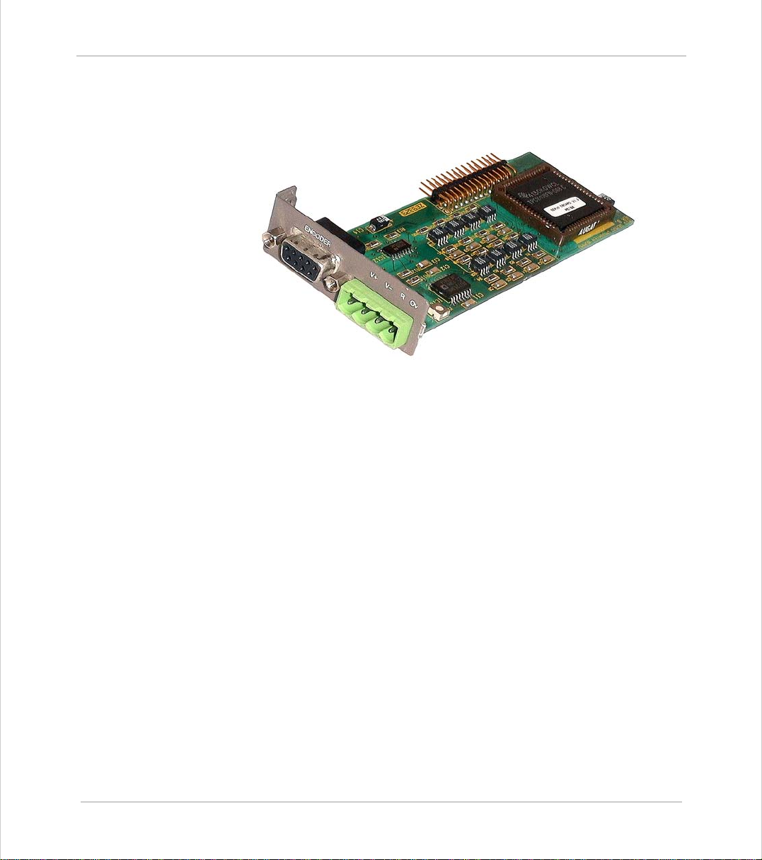
Motion Coordinator Technical Refe ren ce Ma n ual
Description
The axis daughter boards give the Motion Coordinator system enormous flexibility in its configu r ation.
The number of daughter boards which may be fitted is dependant on the controller type.
The MC216 and MC224 master units can hold up to 4 daughter boards in any combination. Up to 12 further daughter boards can be connected using optional Axis
Expander units (4 daughter boards per unit). Communication Daughter Boards
P290, P291, P292, P295, P296 and P297 can only be fitted in the master unit.
The Euro 20 5 has a single d aught er b oard slo t whi ch can be used to provi de a f ifth
axis in addition to the four axes (maximum) on board.
The MC206 can use a single daughter board to provide a sixth axis in addition to
the five axes (maximum) which are available on the standard controller.
The Motion Coordinator recognises the type of axis daughter board or communications daughter board fitted in each slot. For example, a slot with a stepper
ATYPE
daughter board fitted will return its
axis parameter as 1:
>>Print atype
1.0000
Also slot 0 fitted with a USB daughter board, will return its
as 21:
COMMSTYPE
parameter
>>Print COMMSTYPE SLOT(0)
21.0000
Daughter Boa rds 4-3
Page 92
Trio Motion Technology
There are 15 types of daughter boards currently available:
Product
Code:
P200 Servo Encoder 2
P210 Servo Resolver 5
P220 Refe rence Encoder 3
P230 Stepper 1
P240 Stepper Encoder 4
P242 Hardware Pswitch 10
P260 Analog Output 6
P270 SSI Absolute Servo 7
P280 Differential Stepper 4
P290 CAN 8
P291 SERCOS * 24
P292 SLM (Drivelink) 22
P295 USB Interface 21
P296 Ethernet * 25
P297 Profibus 23
Note:
For volume / OEM applications, Trio can produce custom daughter boards for
specific custom er applications where required.
Daughter boards marked * are for use with MC206 and MC224 only.
Description
ATYPE/
COMMS
TYPE
Fitting and Handling Daughter Boards
The axis daughter boards are normally supplied fitted into a Motion Coordinator system. If daughter boards need to be moved or replaced the following
sequence must be followed.
The axis daughter boards are supplied in an anti-static bag or box. This should
be used to hold the axis daughter board at all times when not installed in the
Motion Coordinat or.
4-4 Daughter Boards
Fitting and Handling Daughter Boards
Page 93
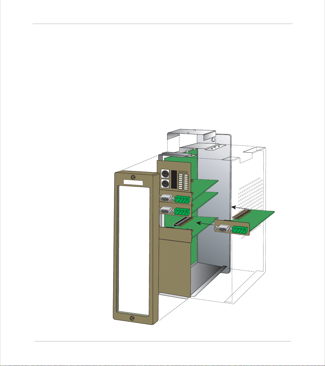
Motion Coordinator Technical Refe ren ce Ma n ual
ENCODER
V+ V- R O
v
ENCODER
V+ V- R O
v
ENC
ODER
V+
V
- R
O
v
ENCODER
Fitting Daughter Boards to the MC216 / Axis Expander
• Check there is no power on the module
• Unscrew the 2 Allen screws whi ch s e cur e the front mo uld i n g c ov er and re mo ve
the cover
• Unscrew the top ribbon cable bus cover. If the ribbon cable is connected,
remove this by pushing the r etaining l evers outwards.
• Unscrew the 8 screws which secure the right hand side cover of the module
• Unscrew the single screw which secures the axis daughter board to the left
hand side of the module. This is located by the left hand end of the axis
daughter front panel
• The sequence is reversed after inserting any new mod ules.
T
ri
o
E
N
C
O
D
E
R
E
N
C
O
D
E
R
V
+
V
-
R
O
v
V
+
V
-
R
O
v
E
N
C
O
D
E
R
E
N
C
O
D
E
R
V
+
V
-
R
O
v
Daughter Boa rds 4-5
Fitting and Handling Daughter Boards
Page 94
Trio Motion Technology
MC216 + Axis Expander Slot Sequence
The slot number of any daughter board is fixed by its position in the MC216/
MC224 module. For standard axis daughter boards, this also fixes the axis
number as shown.
The axis number of any axis daughter board in the Axis Expander module is
fixed by its position an d the setting of the front panel selector switch on the
Axis Expand er.
Location Axis
Slot 0 (Top)
Slot 1
Slot 2
Slot 3 (Bottom)
Location 4-7* 8-11* 12-15**
Slot 0 (Top)
Slot 1
Slot 2
Slot 3 (Bottom)
Axis 4 Axis 8 Axis 12
Axis 5 Axis 9 Axis 13
Axis 6 Axis 10 Axis 14
Axis 7 Axis 11 Axis 15
Axis 0
Axis 1
Axis 2
Axis 3
Where digital drive communications daughter boards are used, the axis
number is set by software and may not necessarily be the same as the slot
number. In any case, with CANopen, SLM and SERCOS, multiple axes can be
controlled v ia a single daughter b o ard.
4-6 Daughter Boards
Fitting and Handling Daughter Boards
Page 95
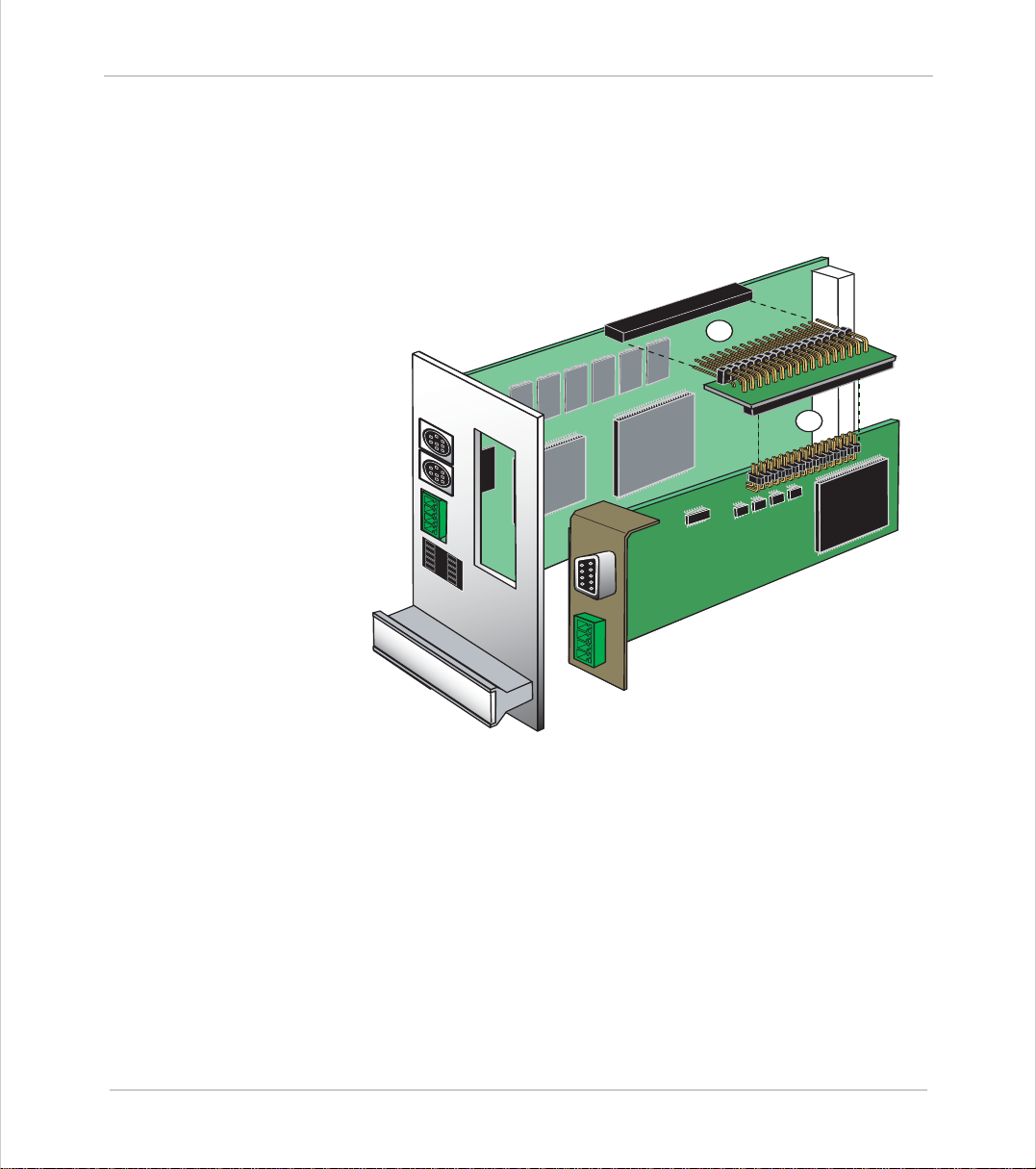
Motion Coordinator Technical Refe ren ce Ma n ual
Fitting Daughter Boards to the Euro205
The Motion Coordinator Euro205 can use a single d augh ter b oard wi th an o ption al
P445 Euro 205 Daughter Board Mounting Kit, which consists of a replacement
(double width) front panel and 90º header connector.
2
1
1
1
Installation Procedure
• Ensure that anti-static precautions are taken when handling the Euro205
board.
• Check there is no power on the module
• Remo ve the standard front panel by undoing the retaining screws from the
rear of the PCB.
• Insert the new daughter board into the bottom of the adaptor, ensuring that
the pins are i nse rte d i nto the holes nearest the fr ont o f t he E ur ocar d as s how n
in the following diagram (#1).
Daughter Boa rds 4-7
Fitting Daughter Boards to the Euro205
Page 96
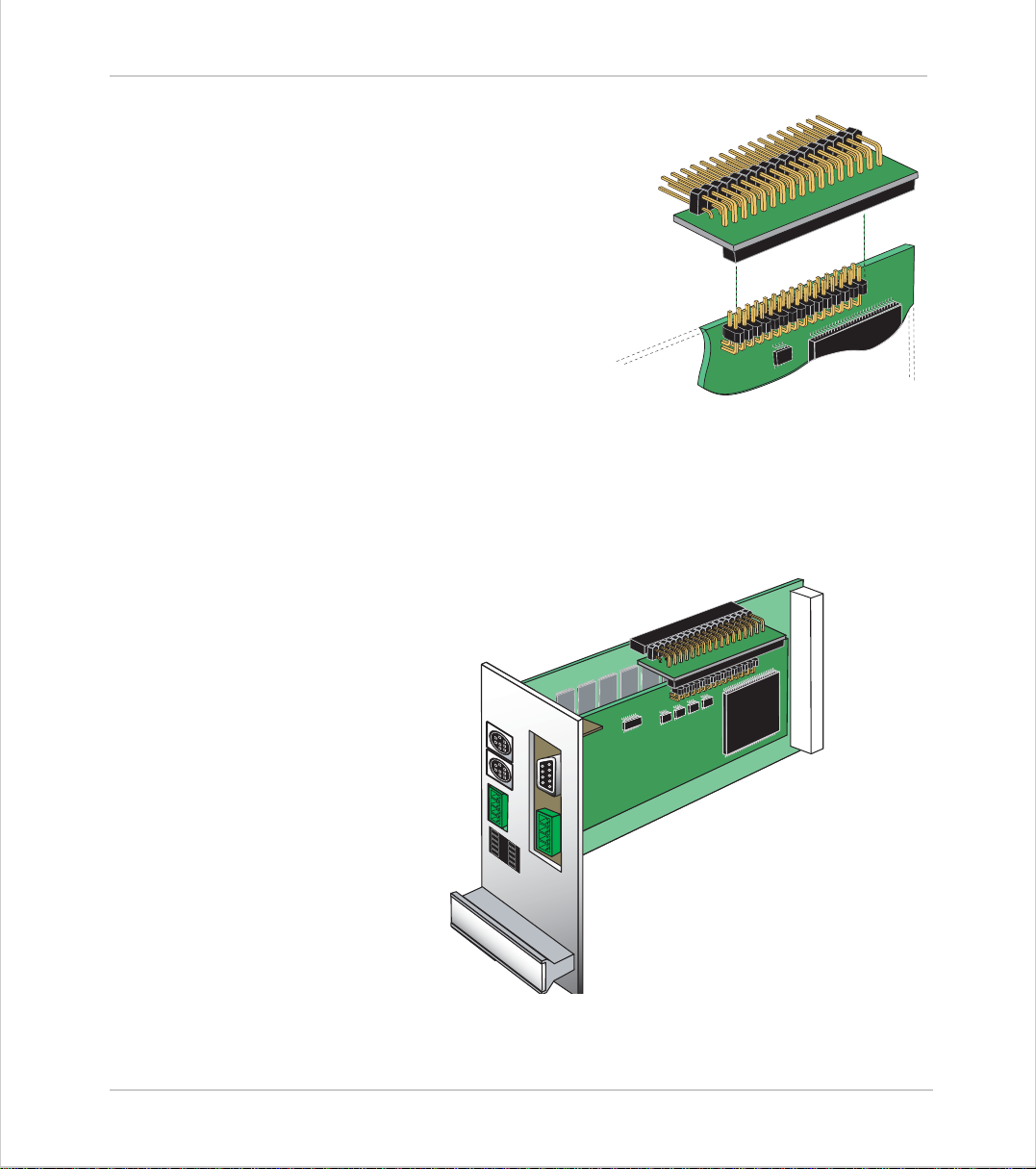
Trio Motion Technology
Note:
Some daughter boards, such as the
CANB us and Profibus communications
boards, feature a longer connector
and so the adaptor features a fulllength socket to accommodate these.
On an axis Daughter Board with the
stand ard (shorter) connector the
board should be inserted into the holes
nearest the edge of the adaptor, as
shown:
• Place the Euro20 5 PCB down o n a firm flat surface and insert the adaptor
pins into the daughter board socket (#2)
• Fit the new front panel, being care fu l to l ine up th e mo un ti ng bra ck e t with
the front panel of the daughter board.
• Insert the ret ain ing s c re w int o the fr o nt pan el bracket to hold t he daughter
board in place.
4-8 Daughter Boards
Fitting Daughter Boards to the Euro205
Euro205 shown with Daughter Board in place
Page 97
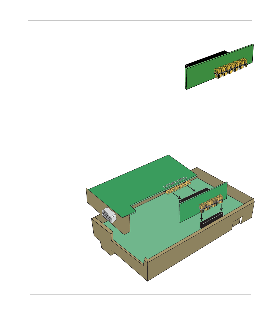
Motion Coordinator Technical Refe ren ce Ma n ual
Fitting Daughter Boards to the MC206
The M otion Coor dinat or MC206 can use a single
daughter board. This is fitted internally, and
connected via the optional P399 MC206 Daughter Board Adaptor (sho w n right) .
The axis daughter boards are supplied in an
anti-static bag or box. This should be used to
hold the daughter board at all times when not
installed in the Motion Coordin ator.
Installation Procedure
• Check there is no power on the module
• Turn the module face-down and carefully remove the back moulding.
To remove the back moulding, a thin bladed small screwdriver needs to be
inserted between the back and front mouldings to release in sequence each of
the five latches which locate the to p edg e of the back on to the fron t.
• Ensure that anti-static precautions are taken when handling the MC206 board.
• Connect the daughter board to the P399 adaptor, and insert the adaptor into
the connector on the MC206 circuit board, as shown below
Daughter Boa rds 4-9
Fitting Daughter Boards to the MC206
Page 98
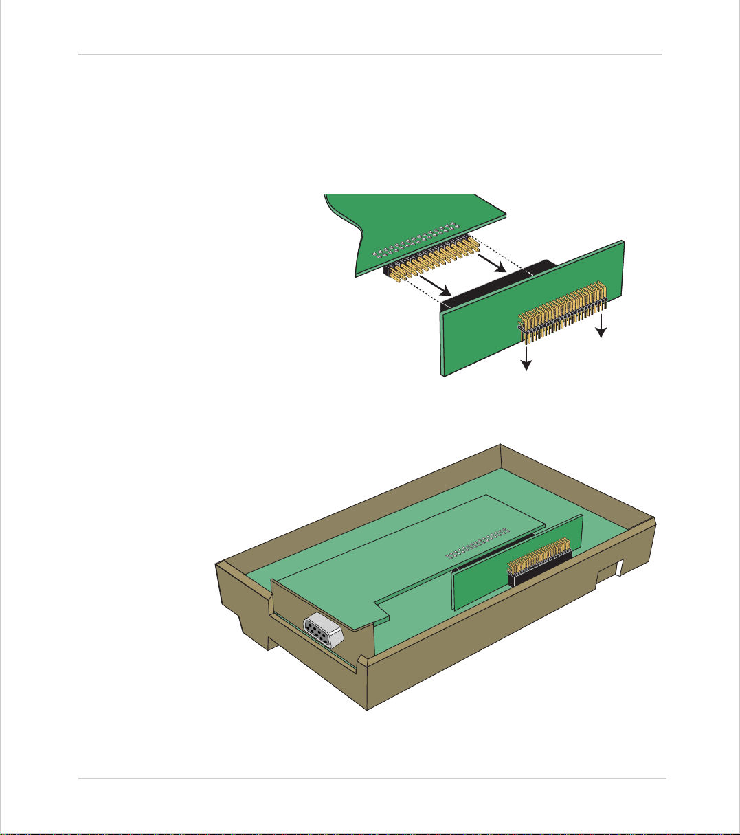
Trio Motion Technology
Note:
Some daughter boards, such as the CANBus and Profibus communications
boards, feature a longer connector and so the adaptor features a full-length
socket to accommodate these. On an axis Daughter Board with the standard
(shorter) connector the board should be inserted into the holes ne arest the
edge of the adaptor, as shown:
Rear of MC206 showing P399 daughter board adaptor
Alignment of MC206 daughter board adaptor
4-10 Daughter Boards
Fitting Daughter Boards to the MC206
Rear of MC206 with Daughter Board In place
Page 99
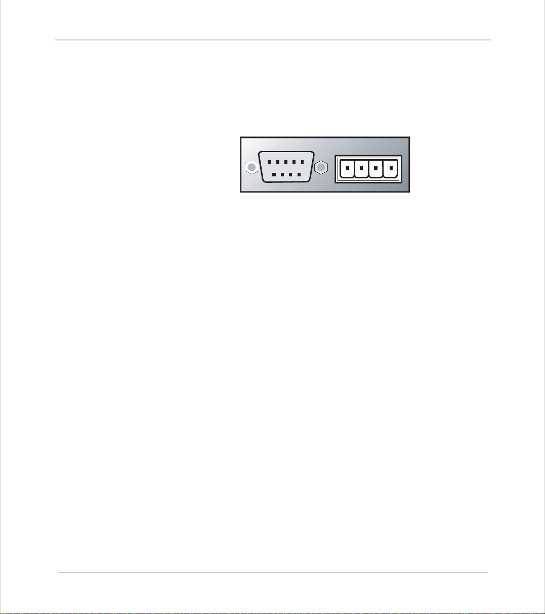
Motion Coordinator Technical Refe ren ce Ma n ual
Servo Encoder Daughter Board
Trio Product Code P200
Description:
ENCODER
21345
98 76
VV+-
R0v
The servo daughter board provides the interface to a DC or Brushless servo motor
fitted with an encoder or encoder emulation.
ATYPE
parameter for S ervo Enc o der Daughter Board = 2
Analog Output
The Servo Encoder Daughter board provides a 12 bit +/-10v voltage output to
drive most servo-amplifiers. The voltage output is opto-isolated as standard to
maximise the noise immunity of the system.
Encoder Inputs
The encoder port provides differential line receiver inputs capa ble of counting up
to 1MHz edge rate . These inputs are opto-isolated to maximise the noi se immunity of the system. The encoder port also provides a convenient 5v output for
power ing the encoder, simplifying wiring and eliminating externa l supplie s.
Registration Function
The Servo Encoder Daughter provides a hardware position capture function for
both the Z input and a dedicated 24volt registration input. Transitions of either
polarity o n bo th th es e in puts can b e used to re cor d th e p os i ti on o f t he axi s at the
time of the event within less than 1 micro seconds. This practically eliminates
time delays and avoids interrupting the processor frequently in multi-axis systems.
Daughter Boa rds 4-11
Servo Encoder Daughter Board
Page 100
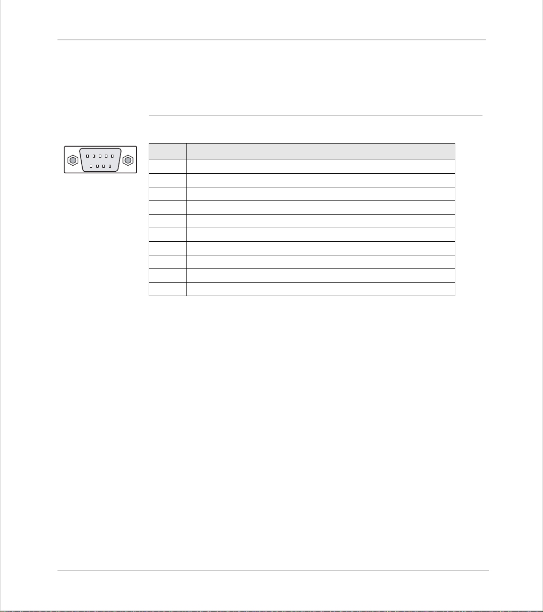
Trio Motion Technology
Connections:
5 4 3 2 1
9 8 7 6
Encoder Connections:
The encoder is connected via a 9 pin 'D' type socket mounted on the front
panel. The plug supplied should be cable mounted and wired as shown below.
The encoder port is designed for use with differential output 5 volt encoders.
Pin. function
1
channel A true
2
channel A complement
3
channel B true
4
channel B complement
5
0V
6
marker (Z) true
7
marker (Z) complement
8
+5V (150 mA max) - This output is short circuit protected
9
Registration Input 5v Input pin
shell
Screen
The encoder may be powered from the +5V supply output on the daughter
board, provided it requires less than 150mA supply current. If the encoder is
situated so far from the module that the supply is inadequate an external supply should be used and regulated locally to the encoder. In this case the +5V
connection from pin 8 should not be used and the external supply 0v should be
connected to pin 5 (0V).
If the encoder does not have complementary outputs, pins 2, 4 and 7 should
be connected to a +2.5v bias voltage. This may be simply derived from a pair
of 220 Ohm res isto rs in s eri es wit h one en d of the p air connect ed to 0v and the
other end to +5v. The centre point of the pair will form approximately 2.5v.
If the encoder does not have a marker pulse, pins 6 and 7 may be left unconnected.
Volta ge Output
The +/-10v output voltage to drive external servo amplifiers is generated
between the V+ and V- pins. The voltage output is isolated and floating but if
multiple servo daughter boards are fitted it should be noted that the boards
share a common power supply for generation of the +/-10v. This means that
4-12 Daughter Boards
Servo Encoder Daughter Board
 Loading...