

Page 1
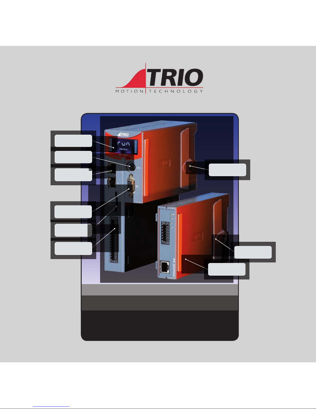
(Please refer to the Motion Coordinator Technical Reference Manual 7 for Full Details)
MO TION COOR DINAT OR
MC464
Quick Connection Guide
BA CK LIT DIS PL AY
ETHERNET
PROGRAMMING
SD CARD
I/O, CAN, POWER,
ANALOGUE
RS232 + RS485
SYNC ENCODER
FIRST EXPANSION
MODULE
EASY RELEASE
EXPANSION COVER
COMMON EARTHING
FOR IMPROVED
NOISE REJECTION
Page 2
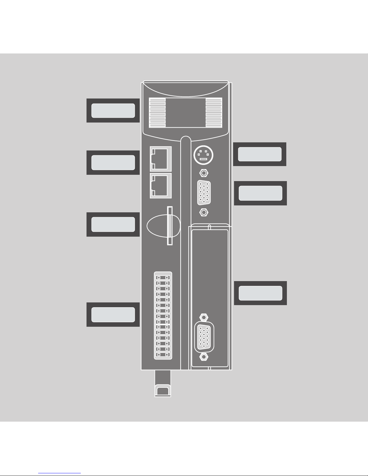
BA CK LIT DIS PL AY
ETHERNET
PROGRAMMING
SD CARD
I/O, CAN, POWER,
ANALOGUE
RS232 + RS485
SYNC ENCODER
FIRST EXPANSION
MODULE
Page 3
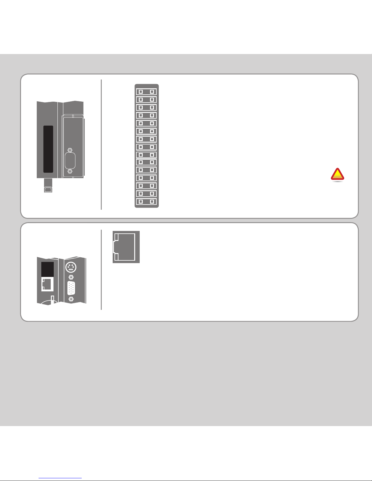
RJ45
CONNECTOR
(TOP)
The bottom 2 pins of the 30 way
high density input connector are
used to provide the 24V dc power
to the MC464. A 24V dc, Class 2
transformer or power source must
be provided.
The 2 pins above the 24V dc supply
are to power the I/O 24 Volts.
The MC464 is grounded via
the metal chassis. It MUST
be installed on an unpainted
metal plate or DIN rail which is
connected to earth.
I/O C ONNE CTOR
A standard ethernet connector is provided
for use as the primary programming
interface.
The Trio programming software, Motion
Perfect 2 or 3, must be installed on a
Windows based PC that is tted with an
Ethernet connection. The IP address is
displayed on the MC464 display for a few
seconds after power-up or when an Ethernet
cable is plugged in.
0V AIN
AIN0
AIN1
WDOG+
WDOG-
I 0
I 1
I 2
I 3
I 4
I 5
I 6
I 7
0V I/O
0V SUPPLY
0V CAN/AIN
CAN LOW
CAN EARTH
CAN HIGH
24V CAN/ AIN SUPPL Y
I/O8
I/O9
I/O10
I/O11
I/O12
I/O13
I/O14
I/O15
24V I/ O SUPPL Y
24V SUPPL Y
!
Page 4
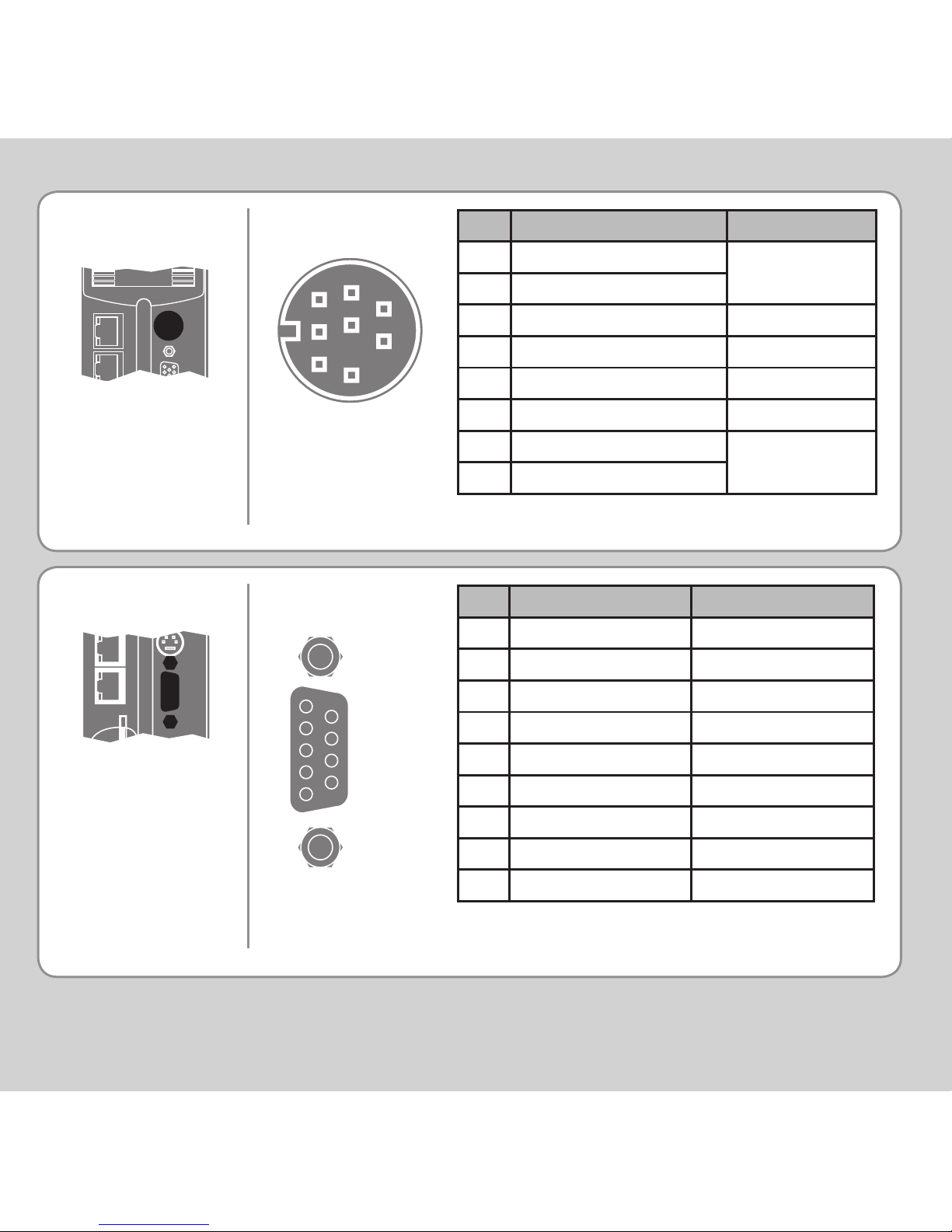
9 Way D-Type
SYNC ENCODE R
CONNECTIONS
* 5V supply is limited to 150mA.
Pin Encoder Pulse & Direction
1 Enc. A Step +
2 Enc. /A Step 3 Enc. B Direction +
4 Enc. /B Direction 5 0V Encoder 0V Stepper
6 Enc. Z Enable +
7 Enc. /Z Enable 8 5V* 5V*
9
Registration Input (5V) Registration Input (5V)
1
2
3
4
5
6
7
8
9
Pin Function Note
1 RS485 Data In A Rx+
Serial Port #2
2 RS485 Data In B Rx3 RS232 Transmit Serial Port #1
4 0V Serial
5 RS232 Receive Serial Port #1
6 Internal 5V
7 RS485 Data Out Z Tx-
Serial Port #2
8 RS485 Data Out Y Tx+
8 Way MiniDIN
8
7
6
5
4
3
1
2
SERIAL
CONNECTIONS
Page 5
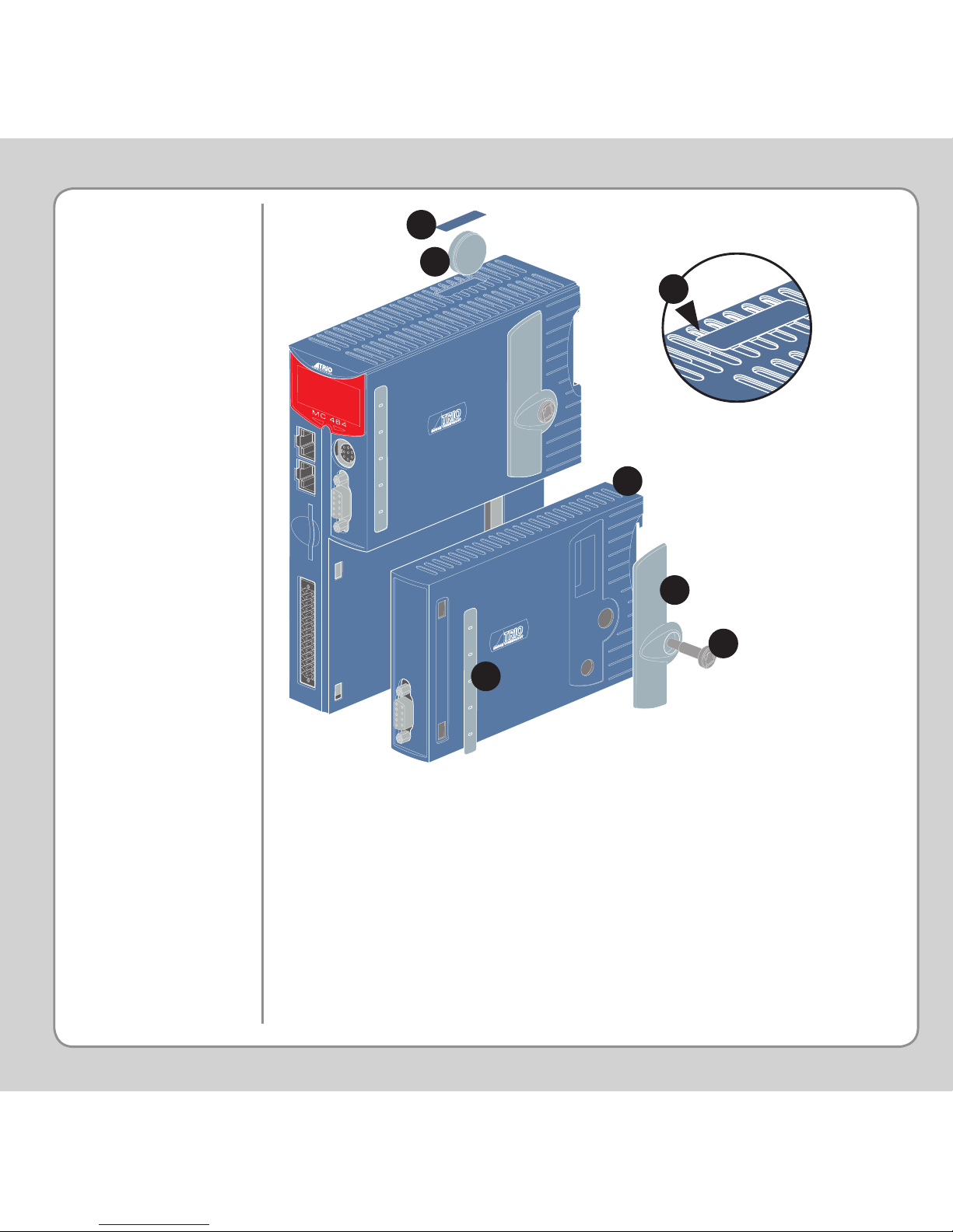
ADDING
EXPANSION
MODULES AND
BATTERY
Unscrew the lower retaining xing (A) using the supplied tool or a
coin.
Remove the covers from the module (B).
Swing the expansion module (C) out from the rear and unclip from
the front end.
Replacing the module is the reverse of the procedure.
To replace the battery, insert screwdriver under the frontmost
ventilation slot (F) and prize off the battery cover (D) and pull the
battery ribbon to lift the battery (E) from the MC464. Replacing is
the reverse of the procedure.
A
C
B
D
E
B
F
Page 6
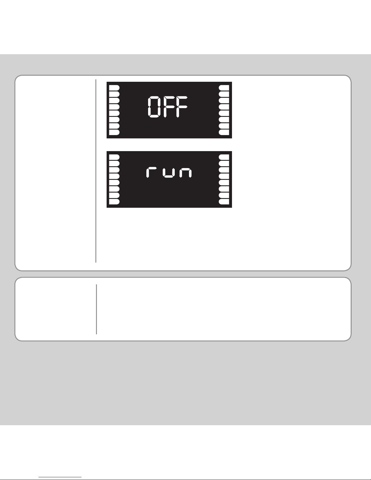
LCD DISP LAY
0
1
2
3
4
5
6
7
8
9
10
11
12
13
14
15
0
1
2
3
4
5
6
7
8
9
10
11
12
13
14
15
ENABLE
Display at start-up
Display with WDOG on
SOFTWARE
Trio recommend that you use the latest version of Motion
Perfect 3 when using the MC464 (Minimum recommended version
MPv3_0_1_4725).
Software can be downloaded from www.triomotion.com.
The IP address and subnet mask of the MC464 is shown on the LCD
display for a few seconds after power-up. The factory default IP
address is 192.168.0.250. This can be changed using the ETHERNET
command via Motion Perfect.
Page 7
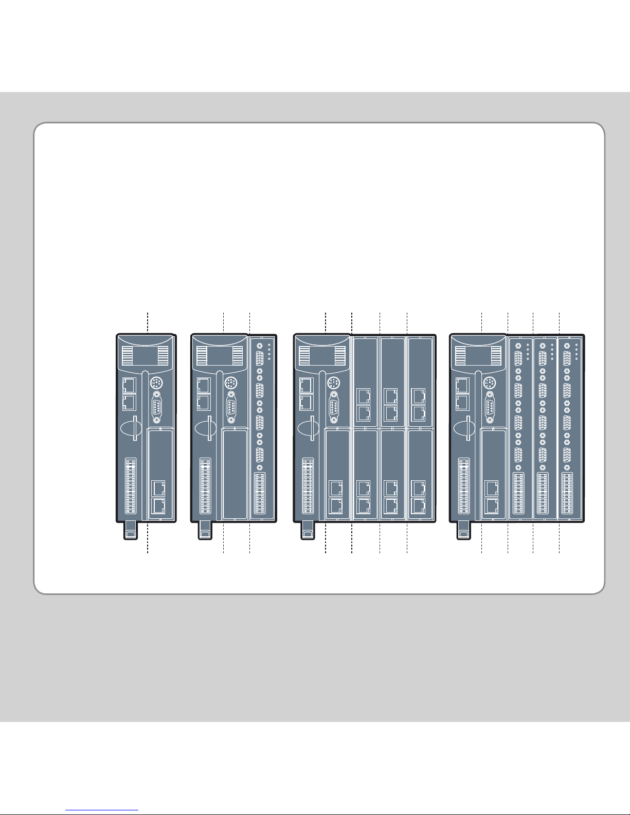
MODULE
ASSEMBLY
A maximum of 7 half height modules or 3 full height modules may be
tted to the MC464. A system may be made using any combination
of half and full height modules providing that the full height modules
are the last to be attached.
SLOT Numbers are allocated by the system software in order, left to
right, starting with the lower bus. Lower modules are allocated slots
0 to m, then the upper modules become slots m+1 to n. Finally, the
Sync Encoder Port is allocated slot n+1. The Sync Encoder Port has
SLOT number -1 in addition to the one allocated (1) in this sequence.
MODULE SLOT
NUMBERS
1 SLOT
SLOT 0
1 0
7 4 5 6
0 1 2 3
4 1 2 3
0
Page 8
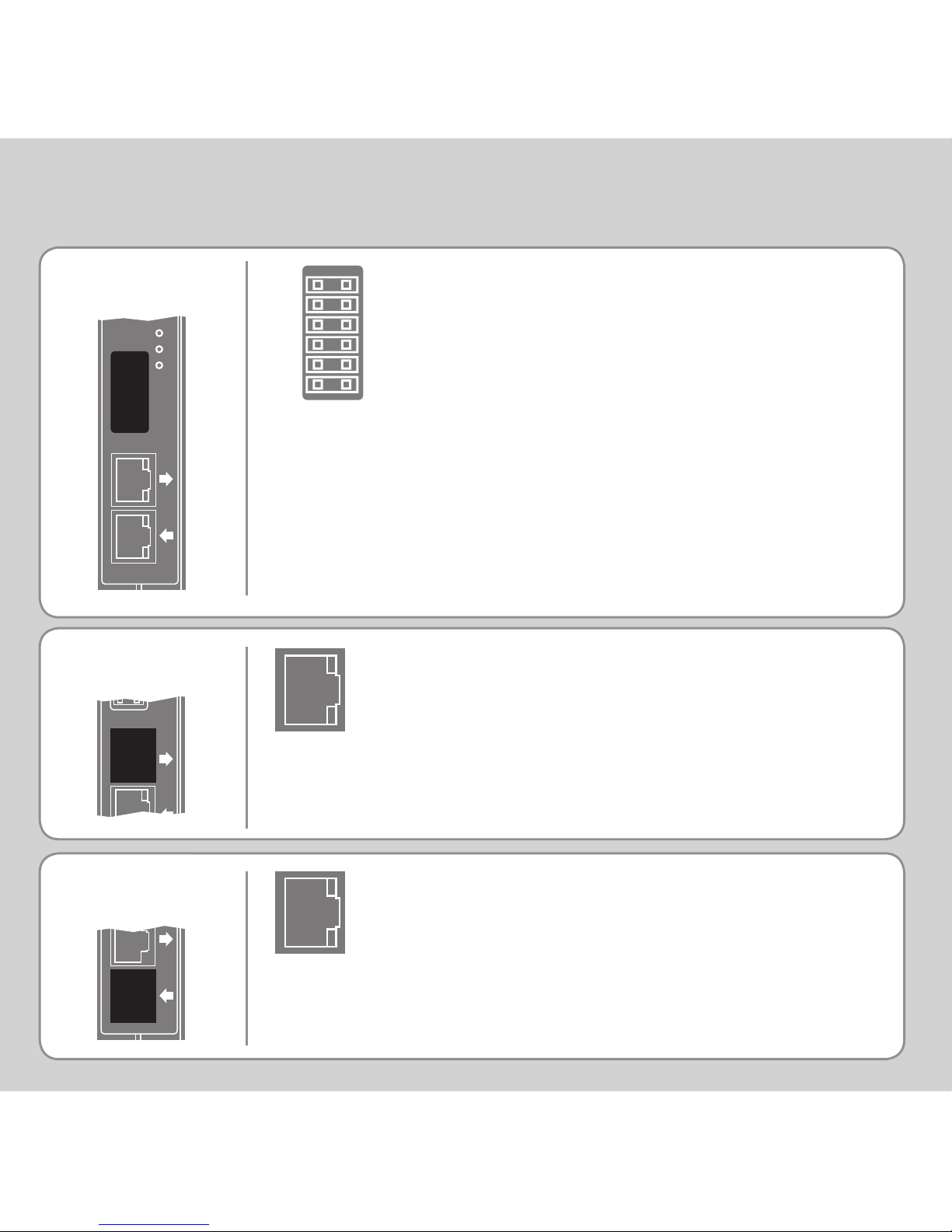
100Mbps Panasonic “Realtime Express”
receive – connect to transmit of last drive.
RJ45
CONNECTOR (TX)
REGISTRATION
CONNECTOR
100Mbps Panasonic “Realtime Express”
transmit – connect to receive of rst drive.
R0 - R7: registration inputs (24V).
R0V: registration common 0V return.
Registration inputs can be allocated to any
axis by software.
Note: This pin out applies to module serial
numbers P871-00011 and higher.
R0
R1
R2
R3
R0V
R0V
R4
R5
R6
R7
R0V
R0V
EXPANSION MODULE P871 - MC464 PANASONIC INTERFACE
RJ45
CONNECTOR ( RX)
Tx
Rx
Tx
Rx
Tx
Rx
ok
0
1
2
Page 9
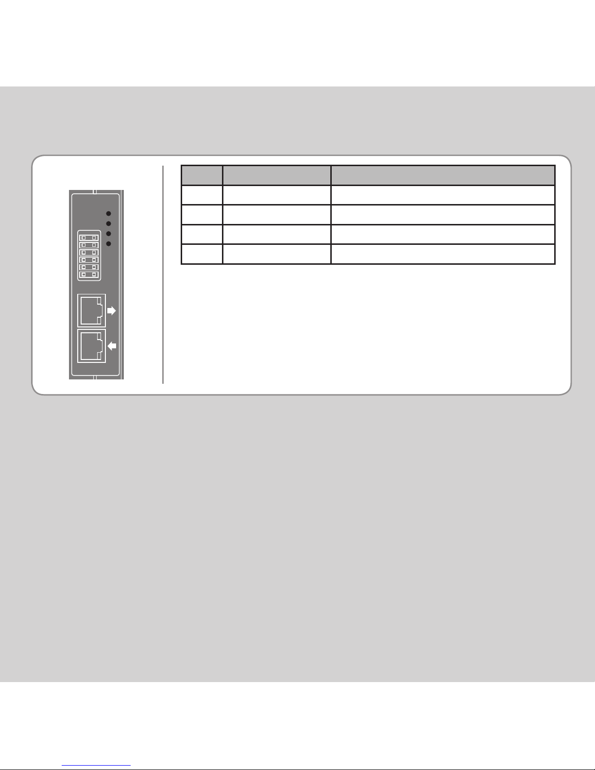
LED FUNCTIONS
LED LED Colour LED Function
ok Green ON=Module Initialised Okay
0 Red ON=Module Error
1 Yellow Status 1
2 Yellow Status 2
Tx
Rx
ok
0
1
2
Page 10
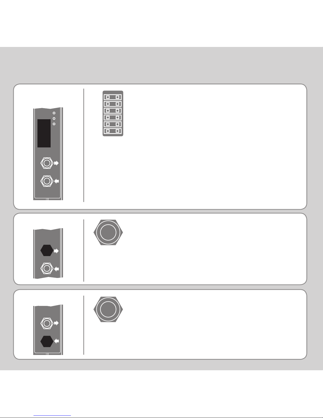
sercos bre-optic receive.
CONNECTOR (TX)
R0 - R7: registration inputs (24V).
0V: registration common 0V return.
Registration inputs can be allocated to any
axis by software.
REGISTRATION
CONNECTOR
sercos bre-optic transmit.
EXPANSION MODULE P872 - MC464 SERCOS INTERFACE
CONNECTOR ( RX)
R0
R1
R2
R3
R0V
R0V
R4
R5
R6
R7
R0V
R0V
9mm FSMA
9mm FSMA
Tx
Rx
ok
0
1
2
Tx
Rx
Tx
Rx
Page 11
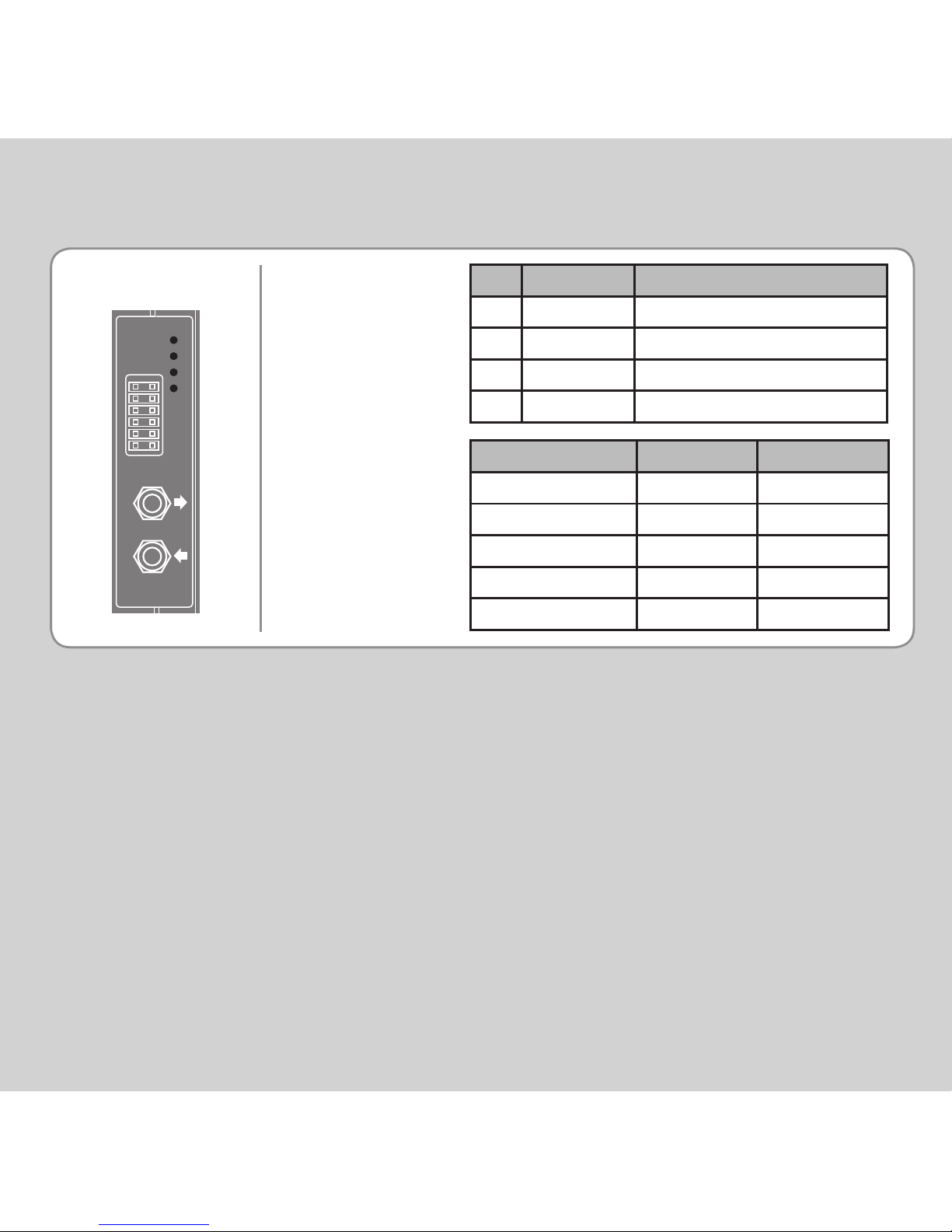
LED FUNCTIONS
LED LED Colour LED Function
ok Green ON=Module Initialised Okay
0 Red ON=Ring Open / Distorted
1 Yellow SERCOS Phase
2 Yellow SERCOS Phase
SERCOS PHASE LED 1 LED 2
0 OFF FLASH
1 OFF ON
2 FLASH OFF
3 ON OFF
4 ON ON
Tx
Rx
ok
0
1
2
Page 12
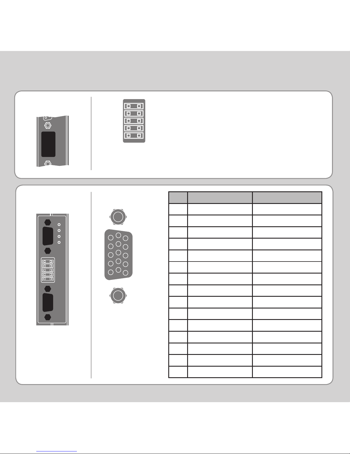
SLM CONNECTOR
REGISTRATION
CONNECTOR
EXPANSION MODULE P873 - MC464 SLM INTERFACE
15 Way D-Type
Pin Upper D-Type Lower D-Type
1 Com Axis 0 Com Axis 3
2 /Com Axis 0. /Com Axis 3
3 Hardware Enable Hardware Enable
4 0V Output 0V Output
5 24V Output 24V Output
6 Com Axis 1 Com Axis 4
7 /Com Axis 1 /Com Axis 4
8 No Connection No Connection
9 No Connection No Connection
10 No Connection No Connection
11 24V Output 24V Output
12 0V Output 0V Output
13 Com Axis 2 Com Axis 5
14 /Com Axis 2 /Com Axis 5
15 Earth / Shield Earth / Shield
R0 - R5: registration inputs (24V).
0VR: common 0V return.
0V PWR:
24V:
R0
R1
R2
R0V
0V PWR
R3
R4
R5
R0V
24V
6
10
1
5
11
15
ok
0
1
2
}
Power input for SLM system.
Page 13
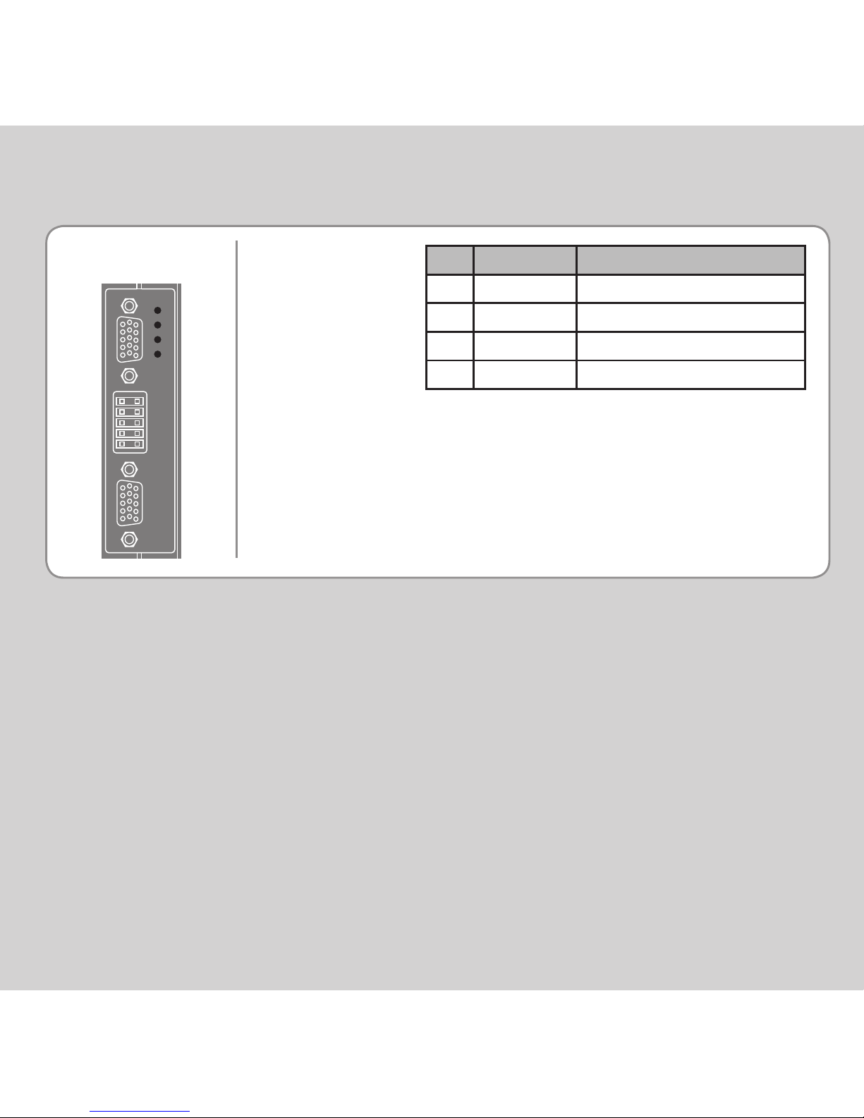
LED FUNCTIONS
ok
0
1
2
LED LED Colour LED Function
ok Green ON=Module Initialised Okay
0 Red ON=Module Error
1 Yellow Status 1
2 Yellow Status 2
Page 14
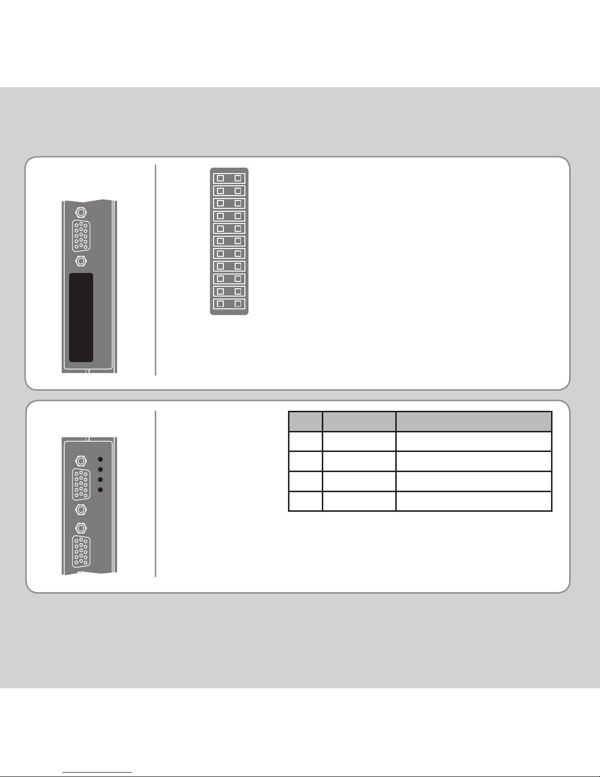
REGISTRATION
CONNECTOR
V0V
V0V
V0
V1
V2
V3
R0
R1
R2
R3
0V PWR
V0V
V0V
V4
V5
V6
V7
R4/PS4
R5/PS5
R6/PS6
R7/PS7
24V
LED FUNCTIONS
LED LED Colour LED Function
ok Green ON=Module Initialised Okay
0 Red ON=Module Error
1 Yellow Status 1
2 Yellow Status 2
EXPANSION MODULE P874 / P879 - MC464 FLEXIBLE AXIS INTERFACE
ok
0
1
2
V0 - V7: Voltage outputs
R4/PS4 - R7/PS7: Bidirectional registration
R0 - R3: Registration In
Inputs / 24V: PSwitch outputs
0V PWR: Power Input
24V: Power Input
V0V: DAC common 0V return
NOTE: 4 axis version uses voltage outputs
0 - 3 only.
Page 15
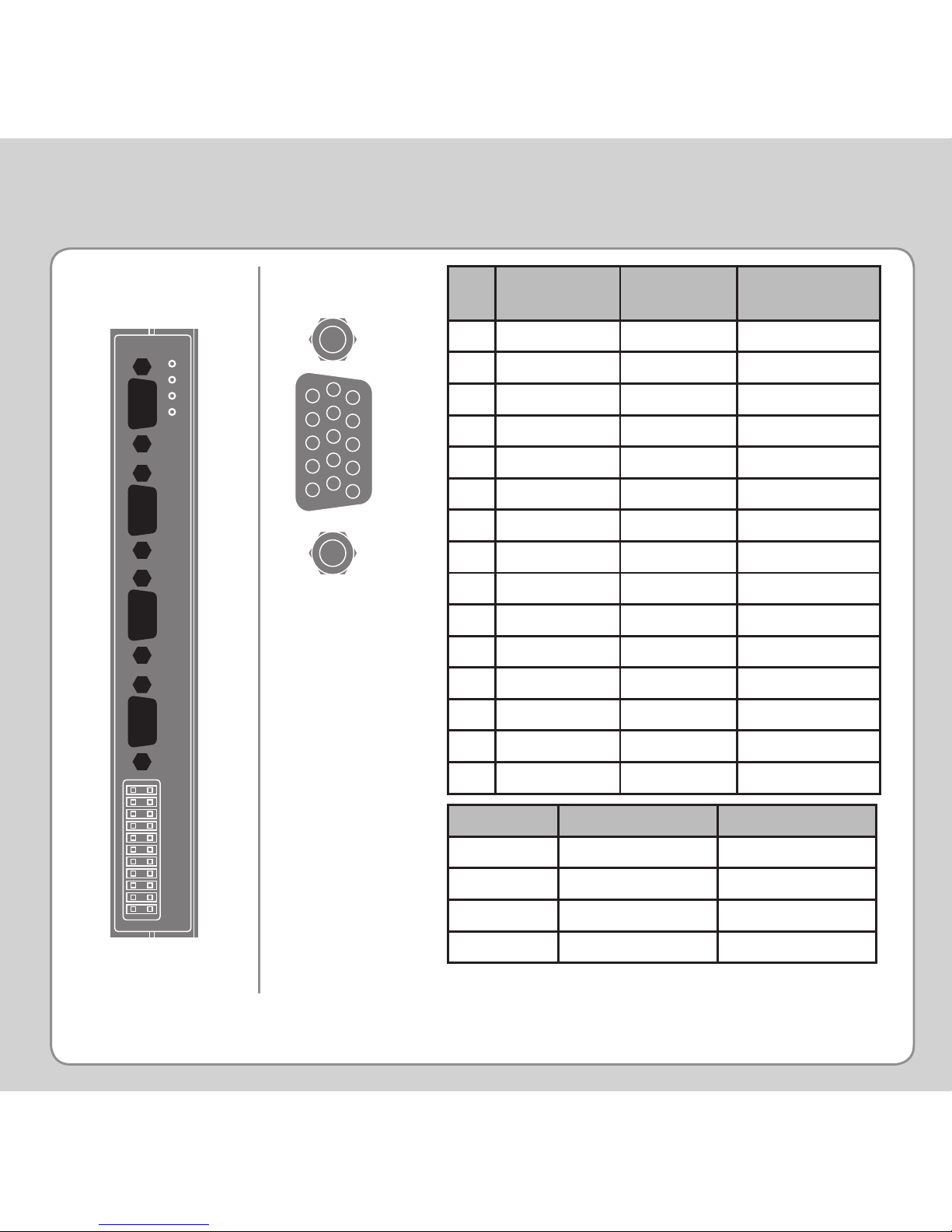
*5V supply is limited to 150mA per axis.
ENCODER
CONNECTOR
15 Way D-Type
Pin Incremental
Encoder
Absolute
Encoder
Pulse &
Direction
1 Enc. A n Clock n Step.+ n
2 Enc. /A n /Clock n Step.- n
3 Enc. B n -------- Direction+ n
4 Enc. /B n -------- Direction- n
5 0V Enc. 0V Enc. 0V Step.
6 Enc. Z n Data n Enable+ n
7 Enc. /Z n /Data n Enable- n
8 5V* 5V* 5V*
9 Enc. A n+4 Clock n+4 Step.+ n+4
10 Enc. /A n+4 /Clock n+4 Step.- n+4
11 Enc. B n+4 -------- Direction+ n+4
12 Enc. /B n+4 -------- Direction- n+4
13 Enc. Z n+4 Data n+4 Enable+ n+4
14 Enc. /Z n+4 /Data n+4 Enable- n+4
15 0V Enc. 0V Enc. 0V Enc.
6
10
1
5
11
15
ok
0
1
2
Connector 8 Axes (P874) 4 Axes (P879)
1 0 and 4 0
2 1 and 5 1
3 2 and 6 2
4 3 and 7 3
1
2
3
4
Absolute Encoder is only available on axes 4 - 7 on
P874 and 2 - 3 on P879.
Page 16
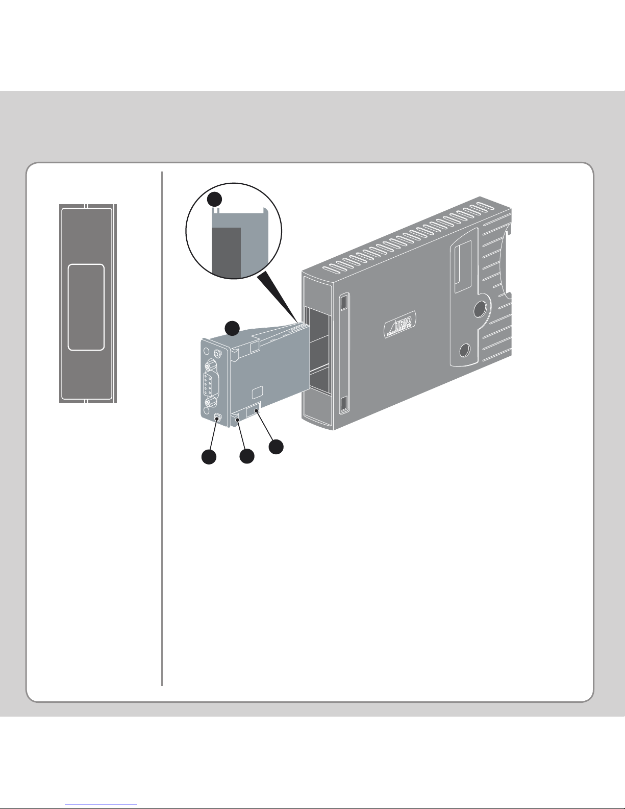
ANYBUS
®
FITTING
EXPANSION MODULE P875 - MC464 ANYBUS® INTERFACE
Push the Anybus® module (A) into the Trio Expansion Interface
taking care to keep its base in contact with the PCB and align guide
slots (B) with the connector rails inside. Ensure that the moulded
hooks (C) on the lower front edge of the Anybus® module locate
under the P875 PCB at the front.
When the module is ush with the face of the Trio Expansion
Interface, tighten the two “Torx” head screws (D) to locate the two
lugs (E) and secure the Anybus® module.
To remove the module, reverse this procedure.
C
D
A
B
E
Page 17
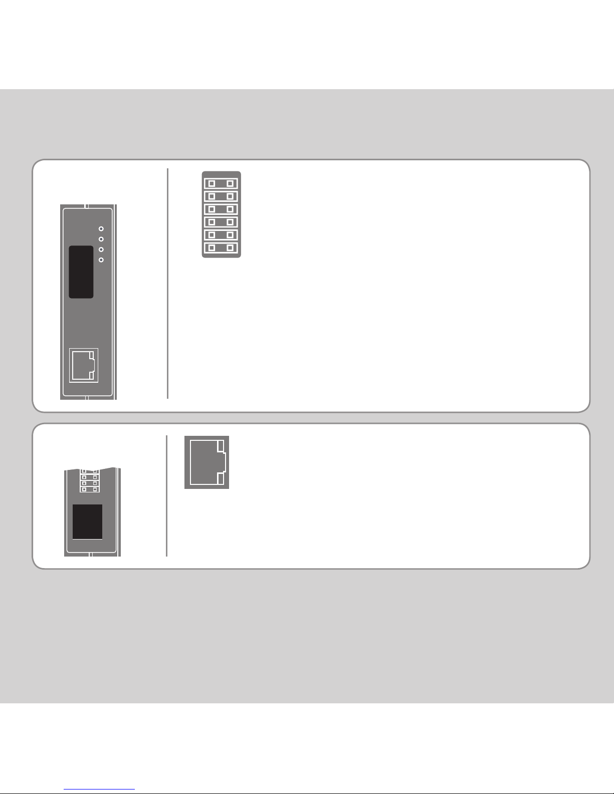
EXPANSION MODULE P876 - MC464 ETHERCAT INTERFACE
RJ45
CONNECTOR
R0 - R7: registration inputs (24V).
0V: registration common 0V return.
Registration inputs can be allocated to any
axis by software.
R0
R1
R2
R3
R0V
R0V
R4
R5
R6
R7
R0V
R0V
100 base-T Ethernet master. Connect to IN of
rst drive.
REGISTRATION
CONNECTOR
Page 18
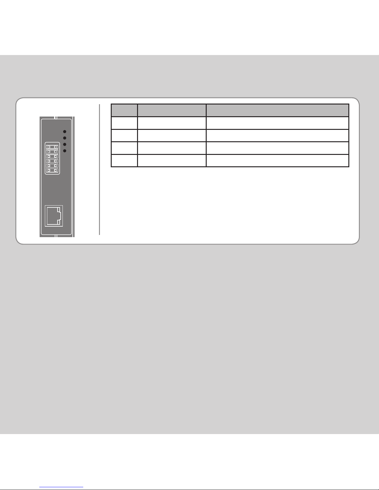
LED FUNCTIONS
LED LED Colour LED Function
ok Green ON=Module Initialised Okay
0 Red ON=Module Error
1 Yellow Status 1
2 Yellow Status 2
 Loading...