

Page 1
(Please refer to the Motion Coordinator Technical Reference Manual for Full Details)
MO T ION C OORDINAT OR
MC405
Quick Connection Guide
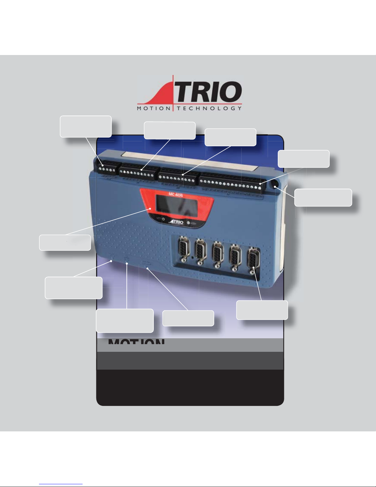
CAN PORT FOR T RIOCAN
I/O, DEVICENET SLAVE,
CANOPEN OR USER
PROGRAMMABLE
8 INPUTS INCLUDING
8 REGISTR ATION INPUTS
8 BI-DIRECT IONAL I/O
2 ANALOGUE INPUTS AND
4 ANALOGUE OUTPUTS,
WDOG RELAY
LED DISPLAY AND
STATUS LED’S
A
Y AND
5 ENCODER CO NNECTIONS
(6MHZ) OR DRIVE AS
STEPPER O UTPUT (2MH Z)
MICRO SD CARD
RS232 / RS485
MODBUS-RTU,
HOSTLINK OR USER
PROGRAMMABLE
ETHERNET
PROGRAMMING, MODBUS-
TCP, ETHERNET IP
PANEL MOUNT AND DIN
RAIL MOUNT
Page 2
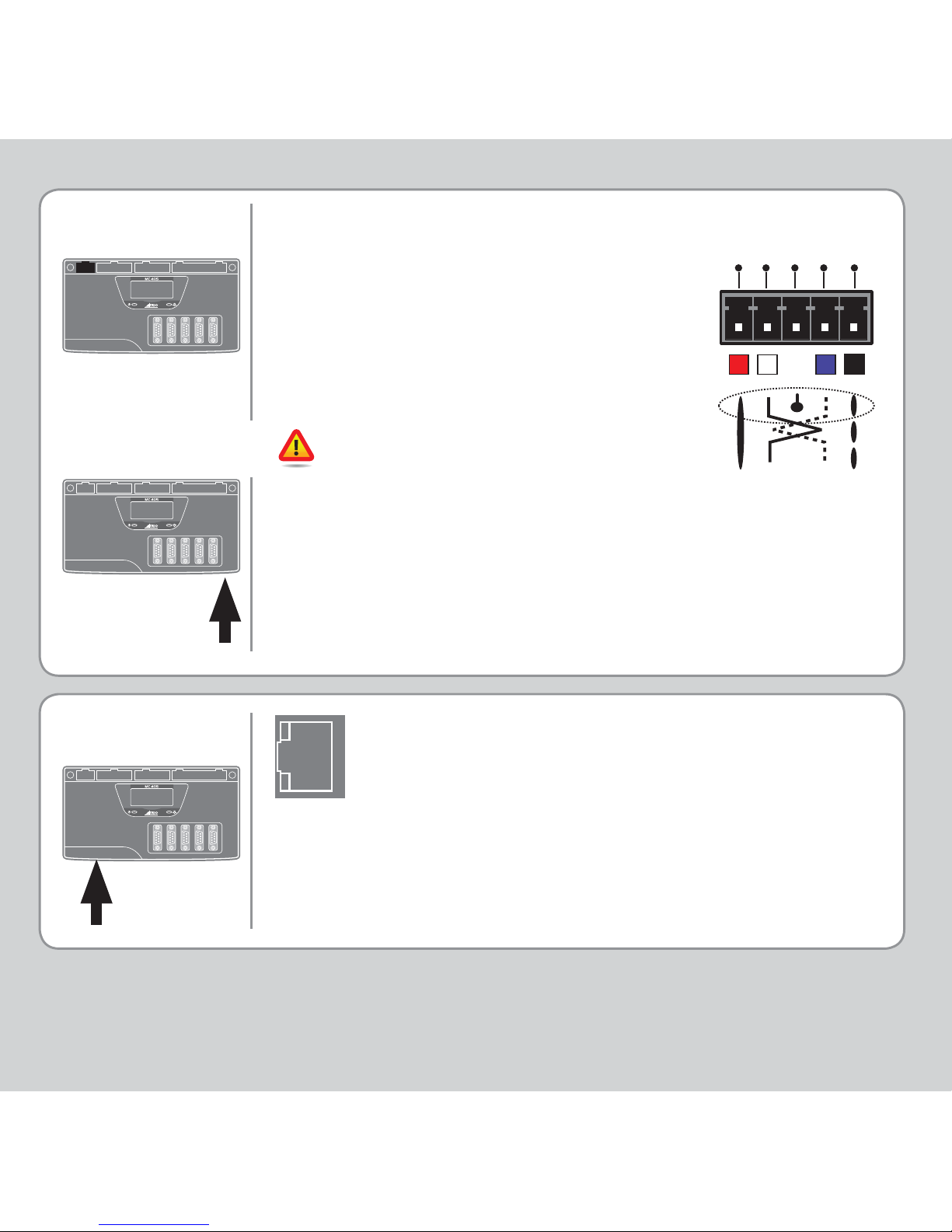
This is a 5 way 3.5mm pitch connector. The
connector is used both to provide the 24 Volt
power to the MC405 and provide connections
for I/O expansion via Trio’s CAN I/O expanders.
A 24V dc, Class 2 transformer or power source
must be provided as this powers the unit.
This 24 Volt input is internally isolated from the
I/O 24 Volts and the +/-10V voltage outputs.
The 24V (V+) and 0V (V-) MUST be connected
as they power the MC405. The MC405 is
grounded via the metal chassis. A screw is
provided on the chassis at the rear to allow
an earth strap connection if needed. It MUST
be installed on an unpainted metal plate or
DIN rail which is connected to earth. The CAN
connections are optional.
5-WA Y
CONNECTOR
V+
SHIELD
CAN
-
L
CAN
-
H
V-
A standard Ethernet connector is provided for use as
the primary programming interface.
The Trio programming software, Motion Perfect, must
be installed on a Windows based PC that is fi tted with
an Ethernet connection. The IP address is displayed on
the MC405 display for a few seconds after power-up or
when an Ethernet cable is plugged in.
Ethernet cable must be CAT 5 or better.
RJ45
CONNECTOR
Page 3
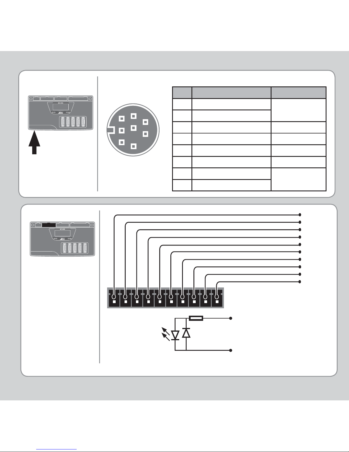
SERIAL
CONNECTIONS
Serial Connector
I/O C ONNE CTOR 1
I/O 0V
I/O 0V
Input 0
Input 1
Input 2
Input 3
Input 4
Input 5
Input 6
Input 7
Optical
Input
Signal
0V Pin
Input Pin
6k8
Pin Function Note
1 RS485 Data In A Rx+
Serial Port #2
2 RS485 Data In B Rx3 RS232 Transmit Serial Port #1
40V Serial
5 RS232 Receive Serial Port #1
65V
7 RS485 Data Out Z Tx-
Serial Port #2
8 RS485 Data Out Y Tx+
8
7
6
5
4
3
1
2
Any input, 0 - 7, may be mapped to any axis as a registration input.
Page 4
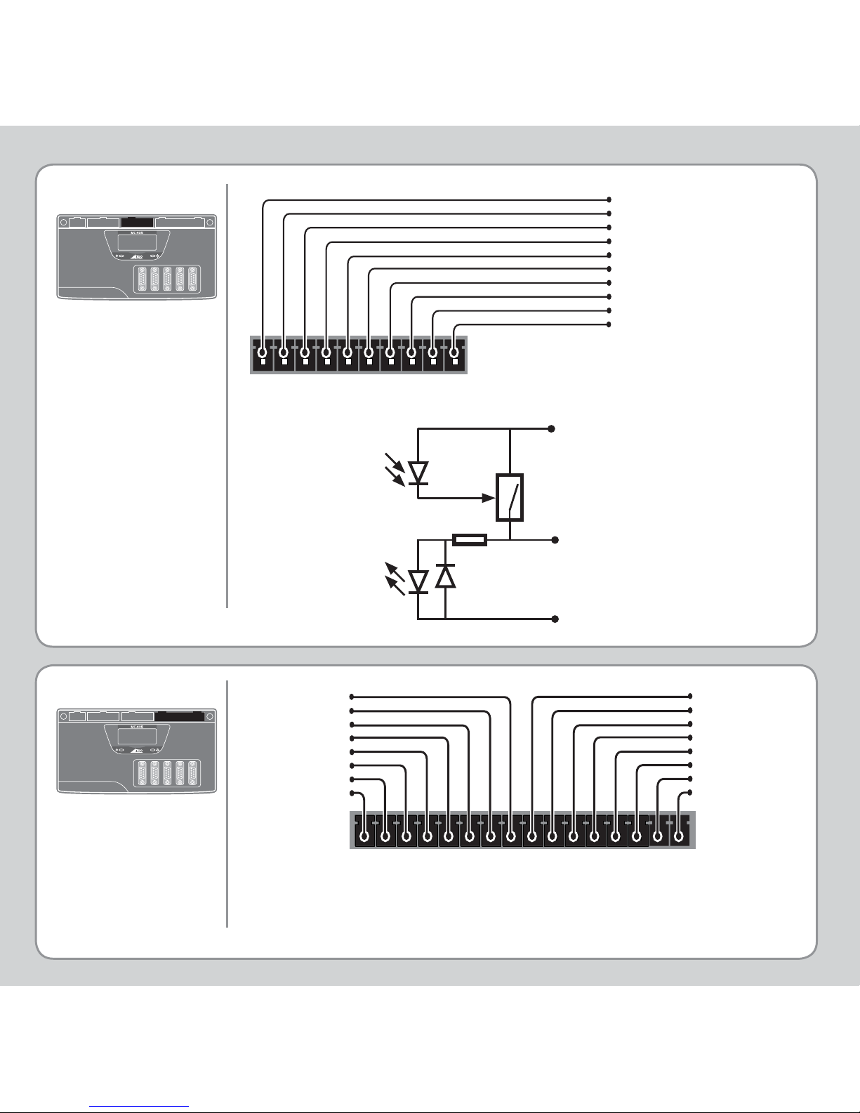
I/O 24V must be applied to power the voltage outputs.
I/O C ONNE CTOR 2
I/O C ONNE CTOR 3
I/O 0V
I/O 24V
Input / Output Channel 8
Input / Output Channel 9
Input / Output Channel
10
Input / Output Channel
11
Input / Output Channel
12
Input / Output Channel
13
Input / Output Channel
14
Input / Output Channel
15
24V Power / I/O 8-15
WDOG / Analogue Inputs / Analogue Outputs
Analogue Out Axis 3
Analogue Out Axis 2
Analogue 0V
N/C
N/C
Analogue 0V
N/C
N/C
Analogue Out Axis 1
Analogue 0V
Analogue Out Axis 0
Analogue Input 1
Analogue Input 0
Analogue 0V
WDOG
WDOG
Optical
Output
Control
Signal
Optical
Input
Signal
24V Pin
0V Pin
Protected
Switch
Input / Output Pin
6k8
Page 5
Aout
0V
100R
100nF
0V
D to A
CONVERTER
Ain
0V
22k
22k
30pF
A to D
CONVERTER
0V
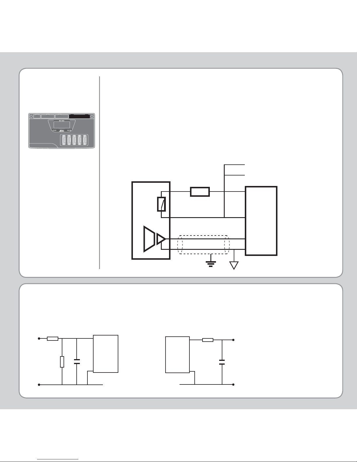
An internal relay is used to enable external amplifi ers when the
controller has powered up correctly and the system and application
software are ready. The amplifi er enable is a single pole solid state
relay with a normally open “contact”. The enable relay contact will
be open circuit if there is no power on the controller OR a following
error exists on a servo axis OR the user program sets it open with
the WDOG=OFF command.
ALL STEPPER AND SERVO AMPLIFIERS MUST BE INHIBITED WHEN
THE AMPLIFIER ENABLE OUTPUT IS OPEN CIRCUIT
ANALOGUE INPUT S
AIN0: 0 TO 10V
AIN1: 0 TO 10V
AMPLIFIER
ENABLE
(WATCHDOG)
RELAY OUTP UT
Amplifi er
Enable 1
Amplifi er
Enable 2
V+
V-
Trio Controller Servo Amplifi er
To other axis enables
24V 0V
0V
Enable
VIN +
VIN-
ANALOGUE OUTPUTS
AOUT 0 TO AOUT 3
Output: +/-10V at 5mA
Output impedance: 100 Ohms.
Common 0V return. Isolated from I/O & Encoders.
Page 6
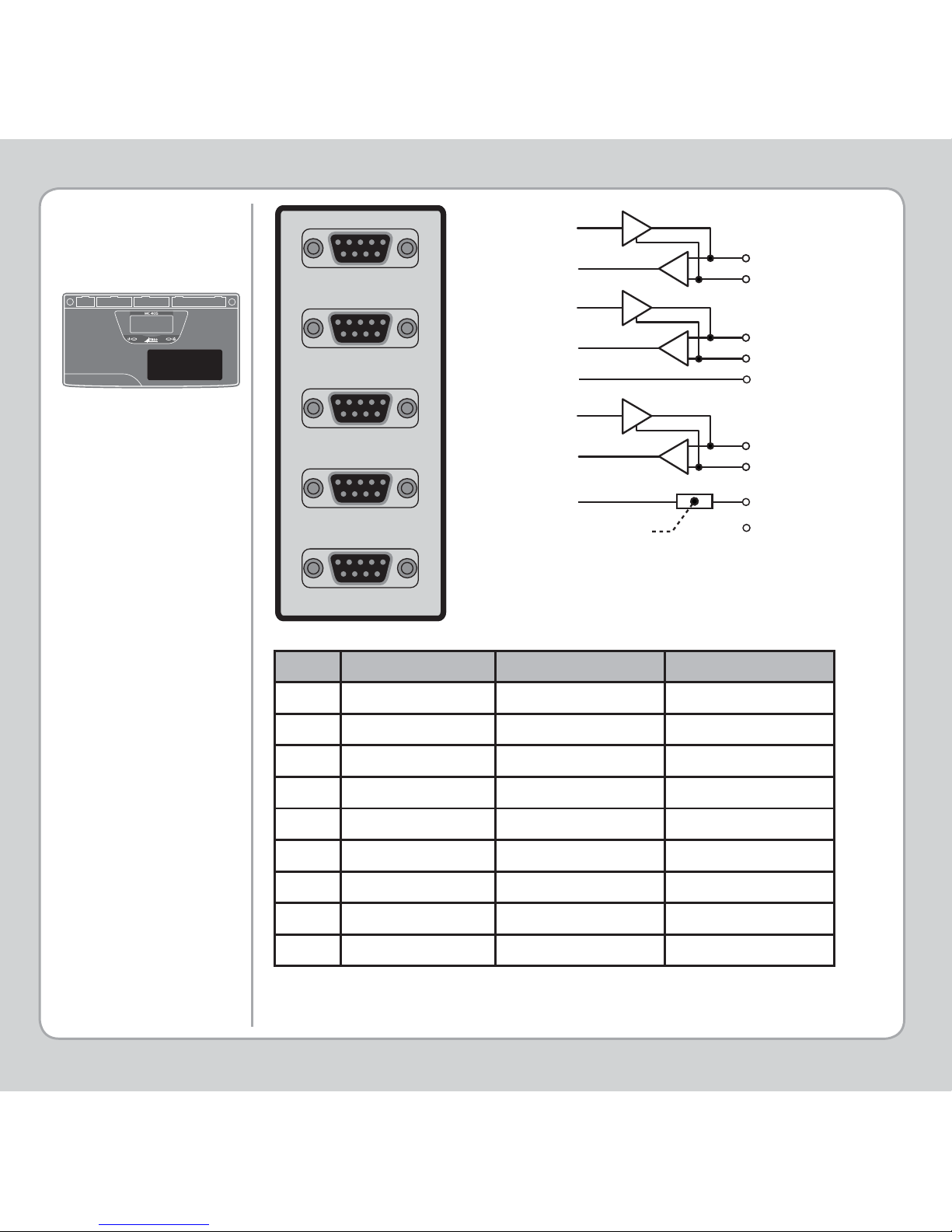
STEPPER
OUTPUTS /
ENCODER INPUTS
* Current limit is 150mA total, shared between all axes.
Pin Servo Axis Stepper Axis Absolute Encoder
1 Enc. A Step + Clock
2 Enc. /A Step - /Clock
3 Enc. B Direction + -------4 Enc. /B Direction - -------50V 0V 0V Enc.
6 Enc. Z Enable + Data
7 Enc. /Z Enable - /Data
8 5V* 5V* 5V*
9 Not Connected Not Connected Not Connected
1
2
A
STEP
3
4
B
DIRECTION
6
7
Z
ENABLE
5
0V
85V
9
NC
Current Limit
5 4 3 2 1
9 8 7 6
5 4 3 2 1
9 8 7 6
5 4 3 2 1
9 8 7 6
5 4 3 2 1
9 8 7 6
5 4 3 2 1
9 8 7 6
Page 7
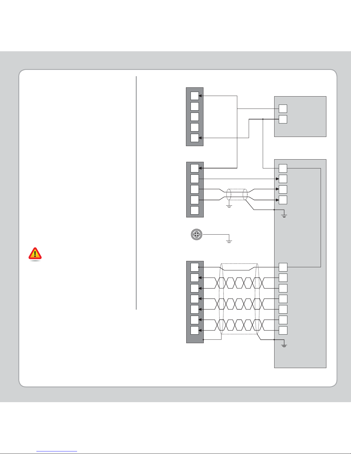
Ensure that:
1. The shield screw is grounded
as close to the MC405 as
possible.
2. 0V, V- and E- connections are
NOT used for terminating
screens.
3. Pin 5 of Encoder/Stepper
plug is connected to 0V on
drive.
4. Encoder cable screen is
clamped to 9 way D shell.
5. The MC405 24V supply has
common 0V with the drive(s).
When wiring MC405 Stepper
outputs to a differential input
stepper drive, use the 0V and
shield connections shown for
the encoder. The stepper
drive must have its common
0V connected to the MC405
24V return. (24V -)
GROUN DIN G AND
SHIELDING
1
2
3
4
5
1
2
8
6
7
5
1
2
3
4
6
7
0V
A+
A-
B+
B-
Z+
Z-
24
0
CONNECTOR SHELL
Enc 0V
Quadrature A
Quadrature B
Z Marker Pulse
Watchdog Relay
Watchdog Relay
Analogue Out 0V Common
Analogue Out Axis 0
Analogue Out Axis 1
SHIELD POINT
Power 24V+
CANbus (H)
SHEILD
CANbus (L)
24V Return (-)
Input Common 0V
Hardware Enable
Speed ref.
Ain -
Ain +
Sheild / Ground
24V POWER SUPPLY
SERVO DRIVE
POWER CONNECTOR
I/O CONNECTOR 3
ENCODER INPUT (9 WAY D-TYPE)
*
Watchdog Relay
Watchdog Relay
Analogue Out 0V Common
Analogue Out Axis 0
Analogue Out Axis 1
* Encoder input 0V MUST be connected to pin 5
Page 8
LCD DISPLA Y
0
1
2
3
4
5
6
7
8
9
10
11
12
13
14
15
0
1
2
3
4
5
6
7
8
9
10
11
12
13
14
15
ENABLE
Display at start-up
Display with WDOG on
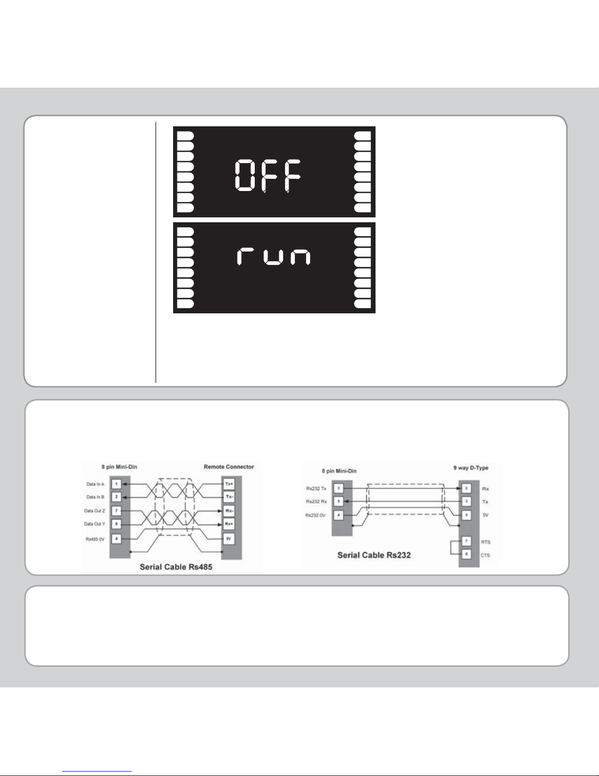
The IP address and subnet mask of the MC405 is shown on the LCD
display for a few seconds after power-up. The factory default IP
address is 192.168.0.250. This can be changed using the ETHERNET
or IP_ADDRESS commands via Motion Perfect.
quick start v2-July 2012
Good quality screened cables should be used for the serial ports. The serial ports and CANbus
port are not galvanically isolated, therefore the 0V return MUST be connected to all peripheral
devices. In addition, bond together the 0V (24V return) terminals of all system components so as
to minimise current fl owing in the serial cables.
Trio Motion Technology Ltd. Trio Motion Technology LLC Trio Shanghai Trio India
Website: www.triomotion.com
 Loading...