

Page 1
QUICK START GUIDE
ELECTROMAGNETIC COMPATIBILITY
ALL MODELS
Page 2

2
INTRODUCTION
Trio Motion Technology products are certied to comply with the requirements
of Annex I to the Directive 2014/30/EU on Electromagnetic disturbance and
Electromagnetic immunity. To achieve this compliance, certain requirements or best
engineering practices must be implemented by the corresponding system designer.
INTENDED CONDITIONS OF USE
Trio Motion Technology products are designed for operation in Industrial environments
with high noise levels that may induce currents or electrical potentials that are
damaging to microelectronics. Our products are nevertheless designed and tested to
withstand the level of electromagnetic disturbance common to these environments, on
the provision that the appropriate EMC guidelines have been employed by a qualied
competent system integrator.
The Trio Motion Technology product range is designed to be integrated, by the
customer, as a control system for industrial machines and auxiliary equipment.
PRODUCT SPECIFIC REQUIREMENTS
Trio Motion’s extensive product and application knowledge combined with product
testing reect that the best immunity is achieved by placing some constraint on the
system into which the product is being integrated. This information is recorded in the
Product Technical Manual (available at www.triomotion.com) and presented in this
document for the commissioning engineer.
Page 3

3
Product Specic Feature Requirements
ALL 0V wire (current
return)
1. Always connect ALL 0V current return wires
2. Do not use the screen for 0V current return
3. It is highly recommended to avoid connecting
0V across internal isolation barriers. If a
single 24V supply is used for the main power
and IO power then these two isolated 0V will
have to be connected but this should only be
done if the 24V supply is free from switching
noise
4. Do not join together 0V from high power and
/ or noisy sources with the 0V from signal
ports (incl. CAN bus DC input)
5. Do not use any controller 0V connection as a
current return for peripheral devices
ALL All 24V DC ports 1. It is highly recommended to use surge lters
on all DC supply and 0V return. If more
than one device is connected to the same
PSU then this is a requirement, (see Surge
Protection on page 6 and Product Technical
Manual)
ALL Cable routing 1. Maintain 150mm separation of parallel Class
I and Class II cable (IEC 61000-5-2:1997) (see
manual)
2. Unless otherwise specied, all cables must
be <30m in length
ALL Proximity to source
of disturbance
1. Place controllers and expansion modules
as far from mains cables, mains lters,
contactors, circuit breakers, drives,
transducers or other high power sources of
EM disturbance as physically possible within
the enclosure design
ALL Enclosure / Safety
Cabinet design
1. Trio’s products should always be installed
within a locked cabinet with access limited
to authorised personnel only
Page 4

4
Product Specic Feature Requirements
ALL Dierential Stepper
/ Encoder Signals
1. Screened, twisted pair cable
2. Connect screen to metal chassis at both ends
(See Cable Shields on page 11 and Product
Technical Manual)
3. 0V reference connected at both ends
ALL CAN bus 1. Screened, twisted pair cable with
characteristic impedance of 120 Ohm (±10
Ohm)
2. Connect screen to Chassis at every node
ALL Digital I/O 1. It is highly recommended to separate PSU
and 0V return (the I/O is internally isolated)
ALL ADC / DAC 1. Use DAC 0V reference pin not common 0V
ALL RS232 / RS422 /
RS485 Serial ports
1. Screened cable
2. Connect screen to Chassis at both ends
3. 0V reference connected at both ends
4. (See cable shields, page 11 and in Product
Technical Manual)
ALL Ethernet 1. Overall Foil Braided Shield / Unshielded
Twisted Pair, (Compliant with Industrial SF/
UTP and TIA Cat5e, minimum)
2. Cable ≤30m in length
ALL Ether C AT 1. Overall Foil Braided Shield / Unshielded
Twisted Pair, (Compliant with Industrial SF/
UTP and TIA Cat5e, minimum)
2. Connect screen to Chassis at both ends, this
is achieved by the shield connection built in
to the RJ45 socket
3. Cable ≤30m in length
Page 5

5
Product Specic Feature Requirements
Controllers
with metal
chassis or
metal back
panel
Protective Earth
Connection
1. Mount on bare metal backplane
2. Use a minimum 4mm wide but preferred
10mm wide, braided conductor to connect
Chassis to PE, as close to the Motion
Coordinator as possible
3. (See EMC Earth on page 9 and EMC Section in
the Product Technical Manual)
Flexslice
Coupler
Flex-6 Nano
Cable routing 1. Cable <100m in length
HMI Uniplay Chassis Ground 1. Connect between FG on the HMI power
terminal and machine chassis or local PE
2. At a minimum: #14 AWG Ground wire
3. Highly recommended: 10mm wide braided
conductor to connect FG to machine chassis
or PE, as close to the HMI as possible
MC4N SD Card Slot 1. Retain plastic slot protector when not in use
MC302X All Cables 1. Screened cable
2. Connect screen to Chassis at both ends
(See Cable Shields on page 11 and Product
Technical Manual)
3. 0V reference connected at both ends
MC4XX /
MC5XX /
MC6XX
Digital I/O 1. Screened cable or EMC Mesh, (due to high
speed inputs)
2. Connect screen to metal chassis at both ends
MC464 RS232 / RS485 1. <3m in length
PC-MCAT All Cables 1. <3m in length except for Ethernet and
Ethercat ports
Page 6
6
RECOMMENDED INSTALLATION
The following diagrams and information detail the typically required Surge Protection,
EMC Earth and Cable Shields however more comprehensive information can be found in
the corresponding Product Technical Manual (available at www.triomotion.com)
SURGE PROTECTION
SINGLE POWER SUPPLY
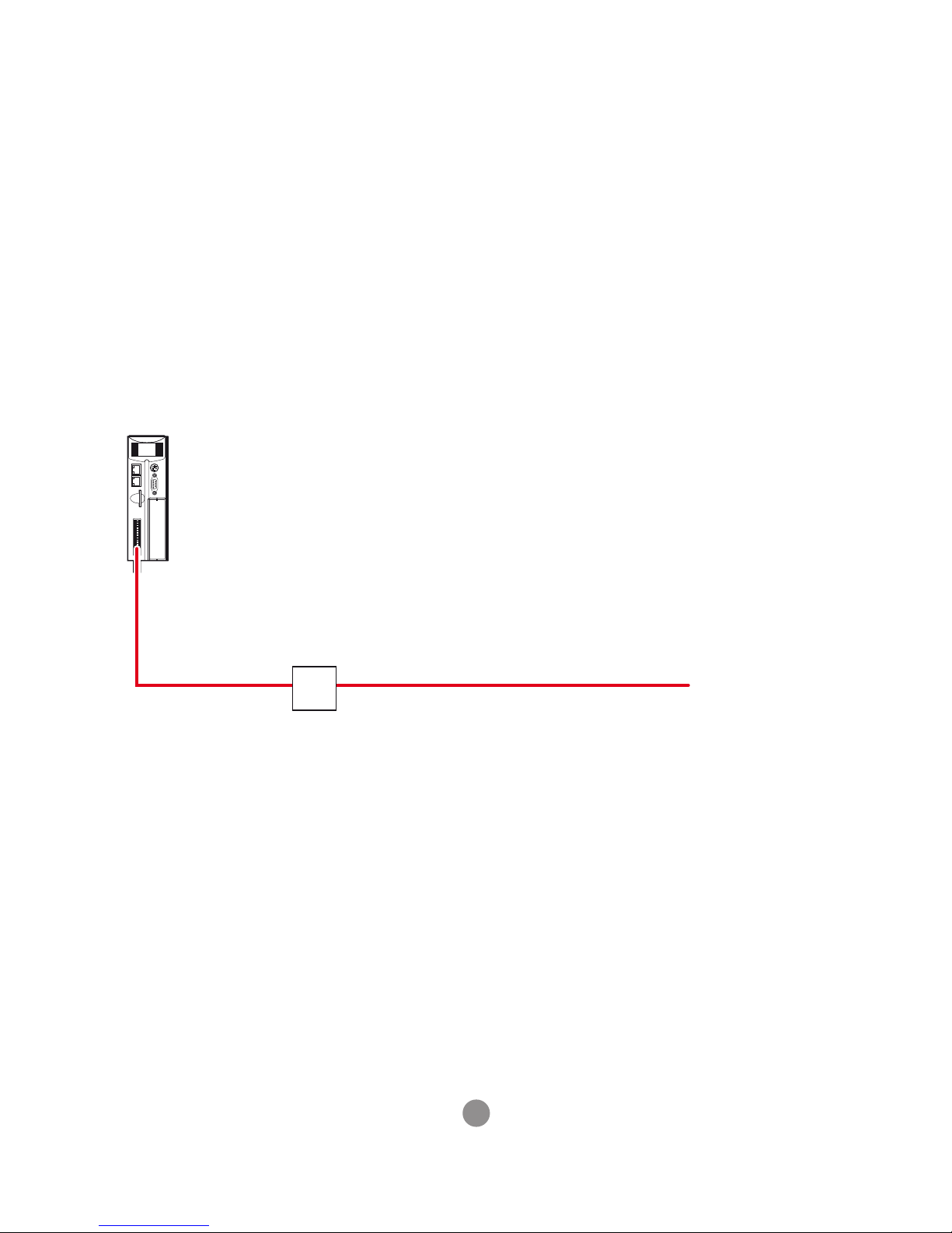
Where the device is supplied with 24V dc from one dedicated 24V power source and
the connecting cable is less than 3 metres, there is no need for a separate surge
protection device.
24V dc
POWER SUPPLY
AC
SUPPLY
< 3M LONG
Motion Coordinator
Motion Coordinator with dedicated power source
Page 7

7
DISTRIBUTED POWER SUPPLY
If the device is connected to a distributed power supply or the cable length between
the power source and the device is longer than 3 metres, then a surge protection
device must be tted to comply with the CE EMC directive.
I/O MODULES
24V dc
POWER SUPPLY
AC
SUPPLY
SURGE
PROTECTOR
SURGE
PROTECTOR
SURGE
PROTECTOR
SURGE
PROTECTOR
Distributed power supply with surge protection
MC664 / MC464 AND IO DEVICES
24V
0V
EARTH
24V
0V
EARTH
SURGE
PROTECTOR
MC464
MC664
Surge protection device
Page 8
8
MC403 / MC405
24V
0V
EARTH
24V
0V
EARTH
SURGE
PROTECTOR
MC464
MC664
24V
0V
EARTH
24V
0V
EARTH
SURGE
PROTECTOR
MC403
MC405
220uf
63V
220uf
63V
Surge protection device
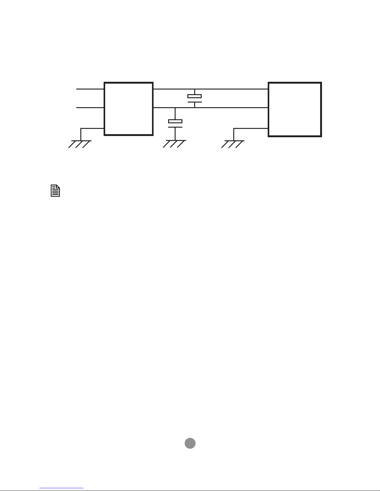
If the I/O power is from a dierent power source to the main device power,
then the I/O power must also have a surge protector tted.
Page 9
9
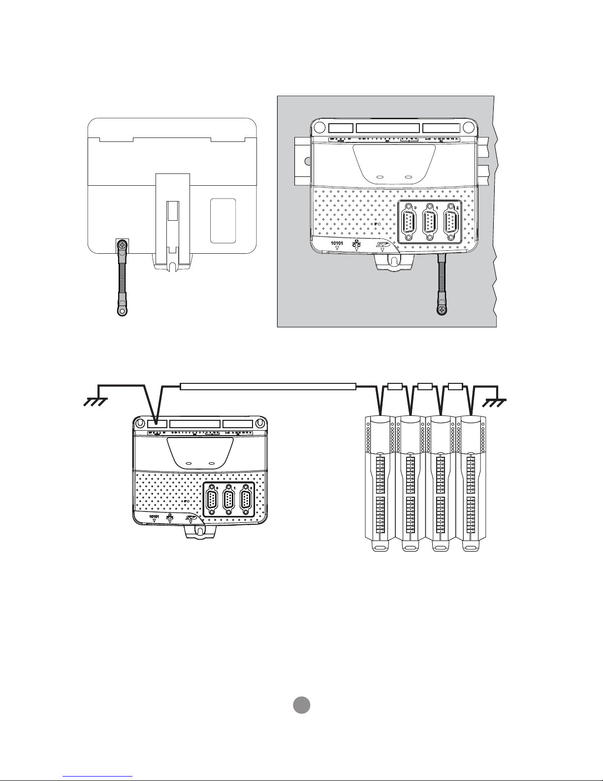
EMC EARTH
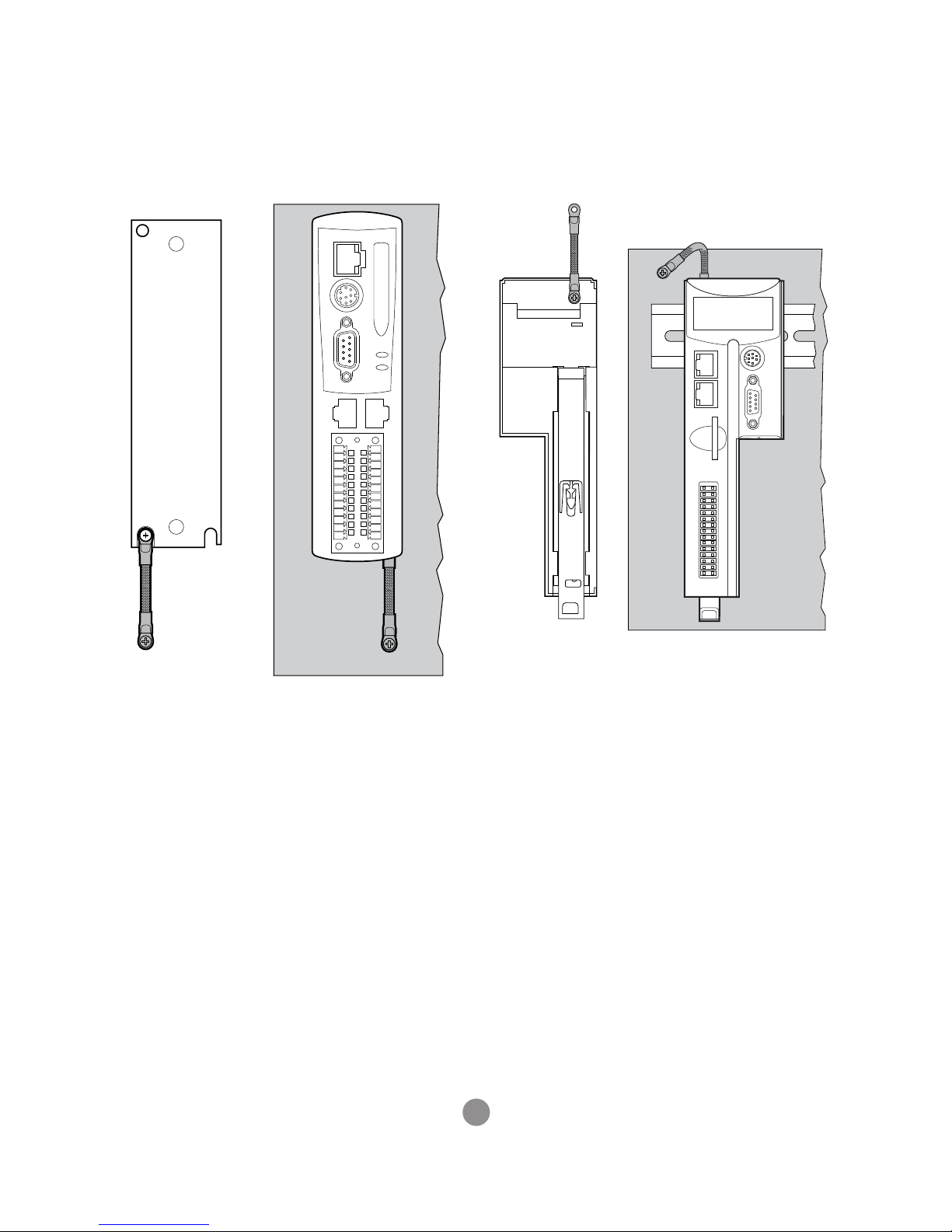
Typical additional earth attachment.
MC4N Earth Braid shown rear (left) and front
(right)
MC664 / MC464 Earth Braid shown rear (left) and
front (right)
Page 10
10
MC403 Earth Braid. MC508 / MC405 is Similar
MC403 and CAN I/O Modules
Page 11
11
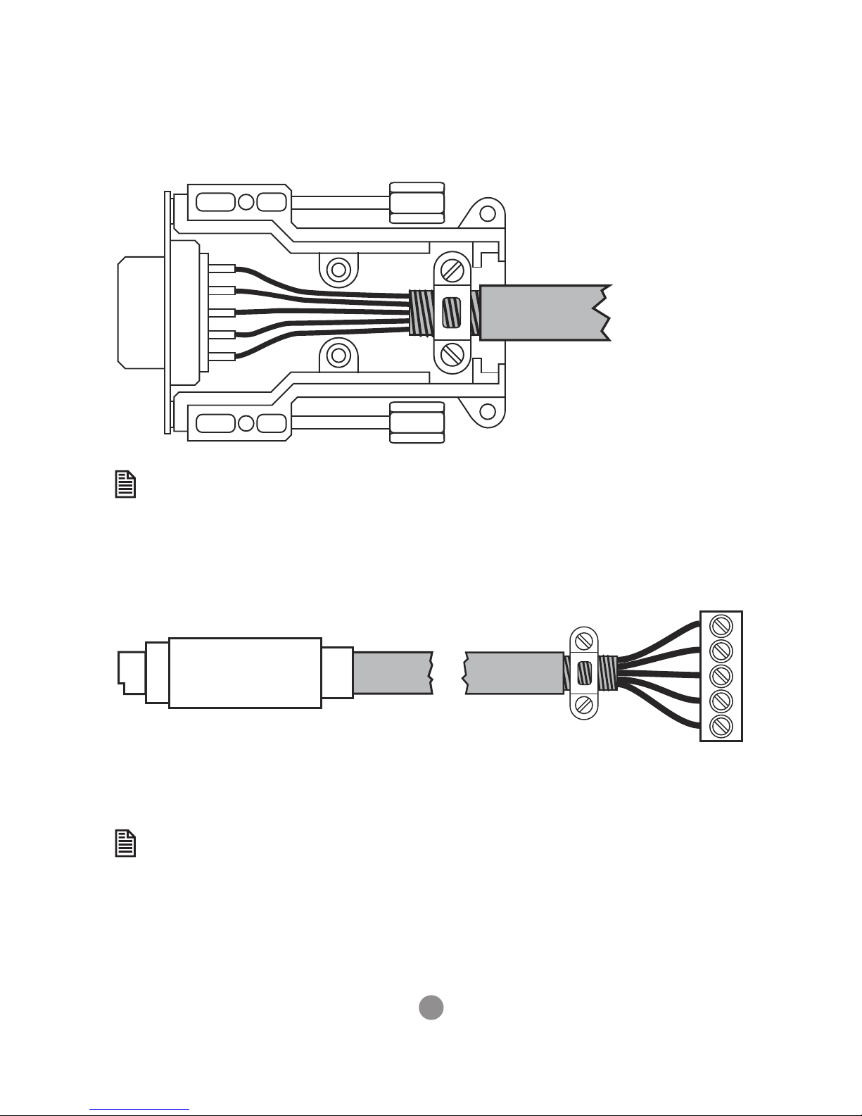
CABLE SHIELDS
Both ends of the encoder cable’s screen must be connected using a 360
degree contact and not a pig-tail connection.
The 0V must be connected separately from the screen. Make sure that
encoder cables are specied with one extra wire to carry the 0V.
SCREEN CONNECTED INTERNALLY
TO METAL SHIELD
SCREEN CLAMPED
TO EARTH
All serial cables must be terminated in an 8-pin mini-DIN connector. For best EMC
performance, clamp the screen of the serial cable where it enters the connector cover.
Do not make a “pig-tail” connection from the screen to the plug cover.
Both ends of the serial cable’s screen must be connected using a 360 degree
contact and not a pig-tail connection.
The 0V must be connected separately from the screen. Make sure that
serial cables are specied with one extra wire to carry the 0V.
This applies to RS422/RS485 serial connections as well as RS232.
Page 12

UK | USA | CHINA | INDIA
WWW.TRIOMOTION.COM
THE MOTION SPECIALIST
CAD data Drawings to aid packaging and mounting are available in various formats
from the Trio web site. Products should be wired by qualied persons.
Specications may change without notice. E & OE
Quick Start v4.0 February 2019
 Loading...