

Trio Flex-6 Nano P601, Flex-6 Nano P602, Flex-6 Nano P600, Flex-6 Nano P603, Flex-6 Nano P604 Quick Start Manual
...Page 1

QUICK START GUIDE
TECHNOLOGY
Flex-6 NaNo
P600 | P601 | P602 | P603 | P604 |P605
ETHERCAT PORT
ETHERNET PORT
STATUS LED’S
MICRO SD CARD
POWER
EBUS CONNECTOR
USER TAB
Page 2

2
Safety Warning
During the installation or use of control systems, users of Trio products must ensure
that there is no possibility of injury to any person or damage to machinery.
Control systems, especially during installation, can malfunction or behave
unexpectedly. Bearing this in mind, users must ensure that even in the event of a
malfunction or unexpected behaviour, the safety of an operator or programmer is
never compromised.
aSSembling the SyStem
One station consists of a P600 Flex-6 Nano and up to 16 Flexslice EtherCAT modules.
1. Align a Flexslice Module against the right hand side of the P600 Module.
2. Slide back the “click-to-lock” mechanism into position.
Removal of Flexslices is the opposite of this procedure.
The complete assembly can be DIN rail mounted.
1
2
Page 3

3
ConneCtorS
Power (24V) connector:
Note: Use ferrules on all wires for best connection.
1. Connection: Push wire into hole of connector. No tools are necessary.
2.
R
emoval: Push screwdriver against coloured button to release wire and pull wire
out.
1 2
Page 4

4
flex-6 nano (P600)
The P600 Flex-6 Nano is a high specication
programmable Motion Coordinator in a compact
format for DIN rail mounting. It is expandable
though the matching Flexslice range of Input, Output
and Axis modules which can be easily added by
clipping to the side of the Flex-6 Nano. In addition,
there is one EtherCAT port (RJ45) for connection of
EtherCAT slave devices including servo and stepper
drives, I/O and other functionality that conforms to
the EtherCAT standard.
A micro SD card slot is provided for memory
expansion, software updates and application use.
Programming and system commissioning is done by
connecting a PC running Motion Perfect v4 to the
upper Ethernet socket.
ConneCtionS
Power Supply
24V dc (±20%) Class 2
transformer or power supply,
0.8A min
Ethernet RJ45
EtherCAT RJ45
Recommended screened cable for EtherCAT;
Cat5 SF/UTP
24V
0V
Micro SD
Card Slot
EtherCAT
Ethernet
Status
LA
RN
Power
Page 5

5
leD’S
Status Red LED
Power Green power LED
RN Green “RUN” LED
O = Initial State
Quick ash = Pre-operational
Slow ash = Safe-Operational
Steady = Operational
LA Green EtherCAT Link/Act LED
rJ45 ethernet ConneCtor (toP)
A standard Ethernet connector is provided for use as the primary
programming interface.
The Trio programming software, Motion Perfect 4.3 or higher, must
be installed on a Windows based PC that is tted with an Ethernet
connection.
The Standard Ethernet connection may also be used for Ethernet-IP,
Modbus and other factory communications.
etherCat Port
The Flex-6 Nano acts as an EtherCAT master. EtherCAT drives and I/O
devices are normally connected in a chain.
Ethernet standard pin assignment:
Pin Signal Description
1 TD+ Transmission data +
2 TD- Transmission data -
3 RD+ Receive data +
6 RD- Receive data -
Straight through (patch) or cross-over cables can be used between EtherCAT devices.
Minimum CAT 5 shielded SF/UTPcable is recommended.
Page 6
6
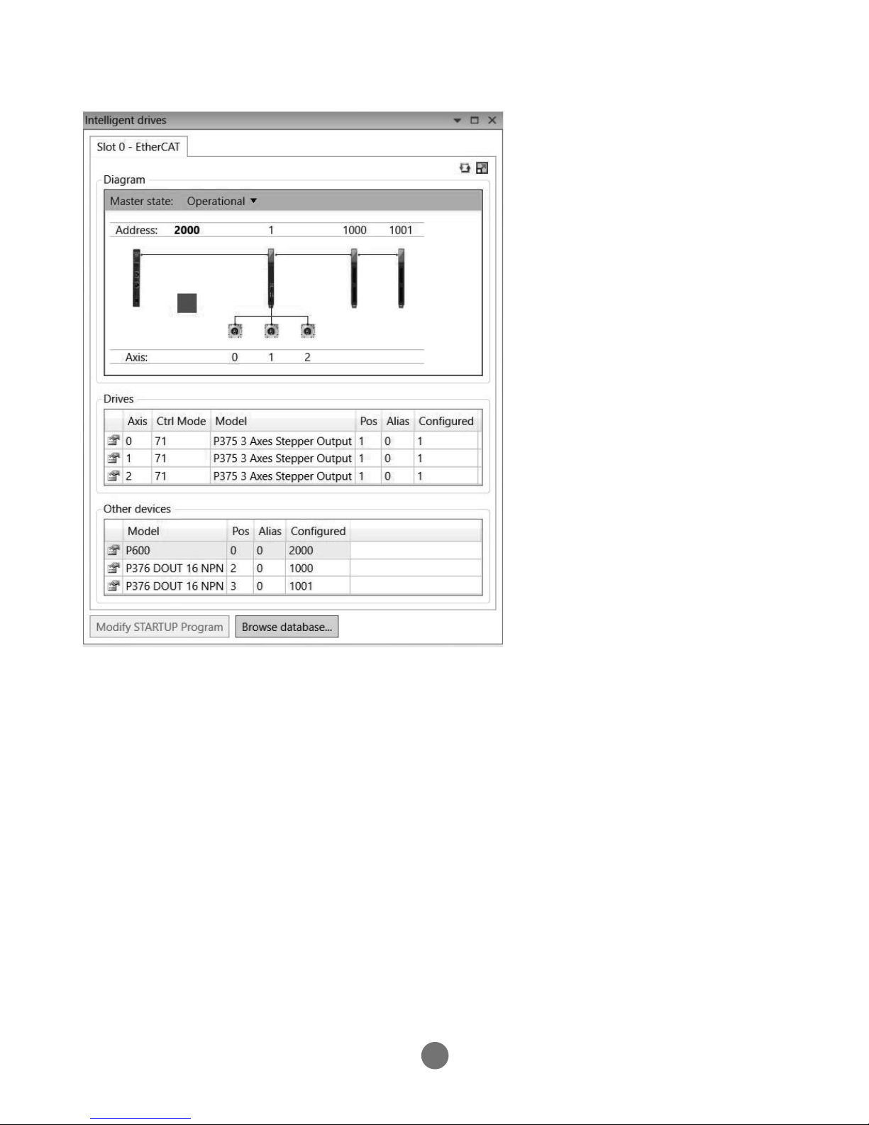
etherCat netWork DeteCtion
EtherCAT Intelegent drives Window in Motion Perfect.
Page 7

7
netWork SetuP
netWork ConneCtion
Set IP_ADDRESS in Flex-6 Nano to an available unused address. The default IP_ADDRESS
= 192.168.0.250. It muS
t m
atch the subnet in use. Set the PC to use DHCP server.
The Flex-6 Nano always has a xed IP address.
Point-to-Point or CloSeD netWork
(No DHCP server)
The PC MUST be set to a xed IP_ADDRESS.
The rst 3 “octets” MUST be the same as the Flex-6 Nano and the last MUST be
dierent, but not 000, 254 or 255.
SwitchPC Laptop Flex-6 Nano
DCHP Server
SwitchPC Laptop Flex-6 Nano
PC Laptop
DCHP Server
Example : 192.168.0.100 Example : 192.168.0.250
Flex-6 Nano
Page 8
8
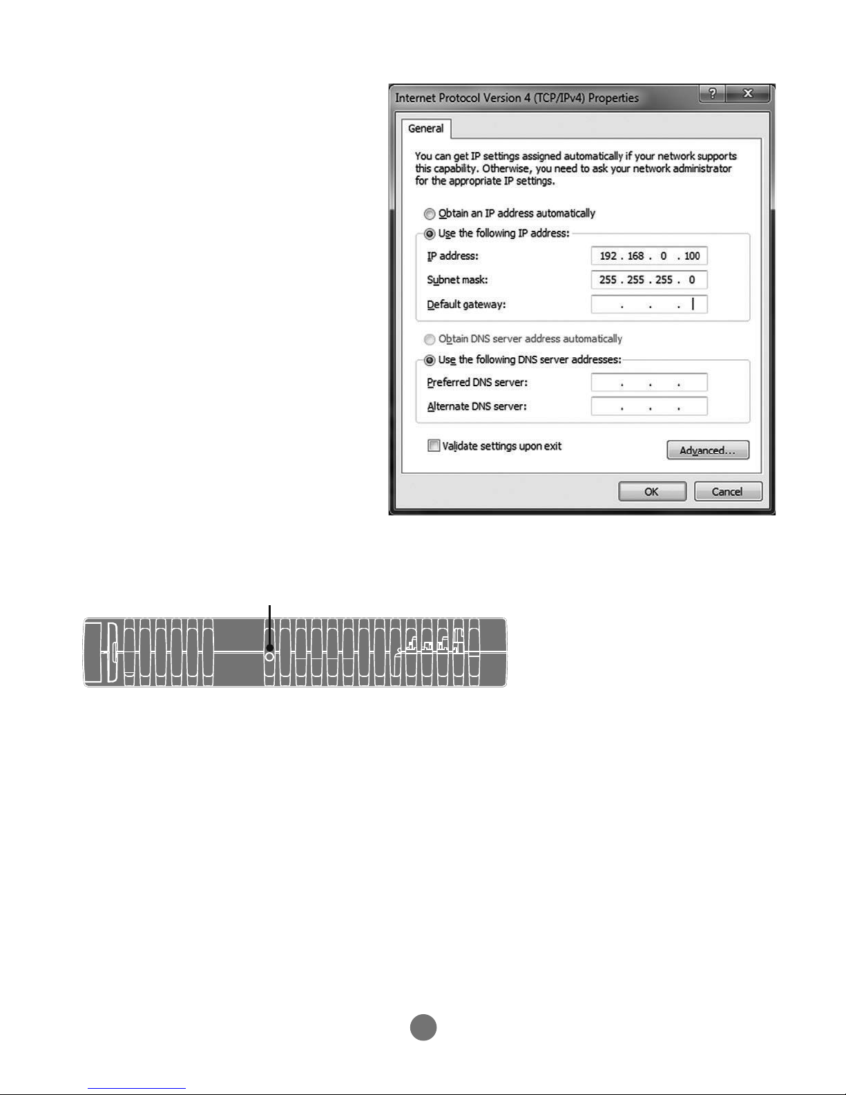
Setting a fixeD iP aDDreSS
I
n Windows 7. Open “Network
and Sharing Centre” then change
“Adapter Settings”. Select the
properties of the Local Area Network
and the IPv4 properties. The IP
Address is set to 192.168.0.100 with
subnet mask set to 255.255.255.0.
Assuming that the Flex-6 Nano has
IP_ADDRESS=192.168.0.250 or similar.
iP aDDreSS reSet
IP Address reset switch
Locate the reset button on the top of the module between the ventilation slots. Hold
down the button using a small screwdrive or similar, while at the same time powering
up the Flex-6 Nano. The IP Address will be set to 192.168.0.250.
Page 9

9
exPanDing the flexSliCe SyStem
The Flexslice system makes available a selection of digital and analogue I/O terminals
as well as motion modules with pulse + direction outputs designed for precise
positioning of stepper and servo motors via suitable drive technology. The digital
I/O modules have high-speed functionality and can sample each EtherCAT cycle, or
use distributed clocks for greater accuracy. In addition, analogue modules and axis
modules may be tted to make a superbly tailored system that can be placed remotely
from the master if needed.
All Flexslice modules support automatic addressing with the master able to
automatically detect and congure the modules on startup. The Flex-6 Nano supports
up to 16 input/output modules which have a positive mechanical lock and bus
connector, making a reliable “back-bone” style connection (EBUS). The complete
assembly can be DIN rail mounted.
Page 10

10
IntentIonally left blank
Page 11

11
IntentIonally left blank
Page 12

UK | USA | CHINA | INDIA
WWW.tRIoMotIon.CoM
THE MOTION SPECIALIST
CAD data Drawings to aid packaging and mounting are available in various formats
from the Trio web site. Products should be wired by qualied persons.
Specications may change without notice. E & OE
Quick Start v1 April 2018
107mm
147mm
15mm15mm15mm
17mm
17mm
DimenSionS
P600
 Loading...