

Page 1

Motion Coordinator Technical Reference Manual
Introduction 1-1
CHAPTER
CHAPTER 0INTRODUCTION
Page 2

1-2 Introduction
Trio Motion Technology
Page 3
Motion Coordinator Technical Reference Manual
Introduction 1-3
Trio Motion Technology’s range of Motion Coordinator products are designed to
enable the control of industrial machines with a minimum of external components. The products may be combined to build a control system capable of driving
a multi-axis machine and its auxiliary equipment. The Motion Coordinator system
described in this manual allows you to control up to 24 servo or stepper motors,
Digital I/O and additional equipment such as keypads and displays from a single
master. Up to fifteen masters can be networked together using the Trio fibre optic
network allowing up to 360 axes of control. The controller is programmed using
the Trio BASIC programming language. This may be used to build stand-alone pro-
grams or commands can be sent from an external computer.
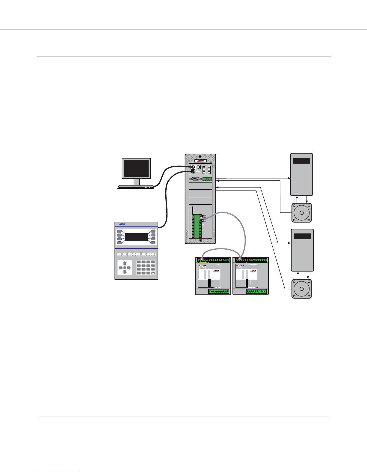
Typical System Configuration
The
Motion
Coordinator system is m odular, allowing the user to tailor the controller
to their specific needs, but also allowing t he flexibility to incorporate new m odules if
needs should change.
ENCODER
V+ V- R
0v
8
9
10
11
12
13
14
15
0
OK
A
B
STA
1
2
3
4
5
6
7
SERIAL
BAT
5 4 3 2 1
9 8 7 6
MOTION
TECHNOLOGY
IO8
IO9
IO10
IO11
IO12
IO13
IO14
IO15
I 0
I 1
I 2
I 3
I 4
I 5
I 6
I 7
24v
0v
A1
A0
A-
B
0
1
2
3
4
5
6
7
8
9
10
11
12
13
14
15
1
2
4
8
16
32
OFF
MS NS
PR
DR
10 11 12 13 14 15 24v Ov98
765432100v24v
NODE
ADDRESS
CAN16 -I/O
0
1
2
3
4
5
6
7
8
9
10
11
12
13
14
15
1
2
4
8
16
32
OFF
MS NS
PR
DR
10 11 12 13 14 15 24v Ov98
765432100v24v
NODE
ADDRESS
CAN16 -I/O
7
4
1
-
8
5
2
0
9
6
3
.
Y
N
CLR
PC for Programming
Operator Interface
Motion Coordinator
CAN I/O
Servo Drive
Servo Drive
Motor
Motor
MOTION
TECHNOLOGY
MOTION
TECHNOLOGY
MOTION
TECHNOLOGY
Page 4
1-4 Introduction
Setup and Programming
Trio Motion Technology
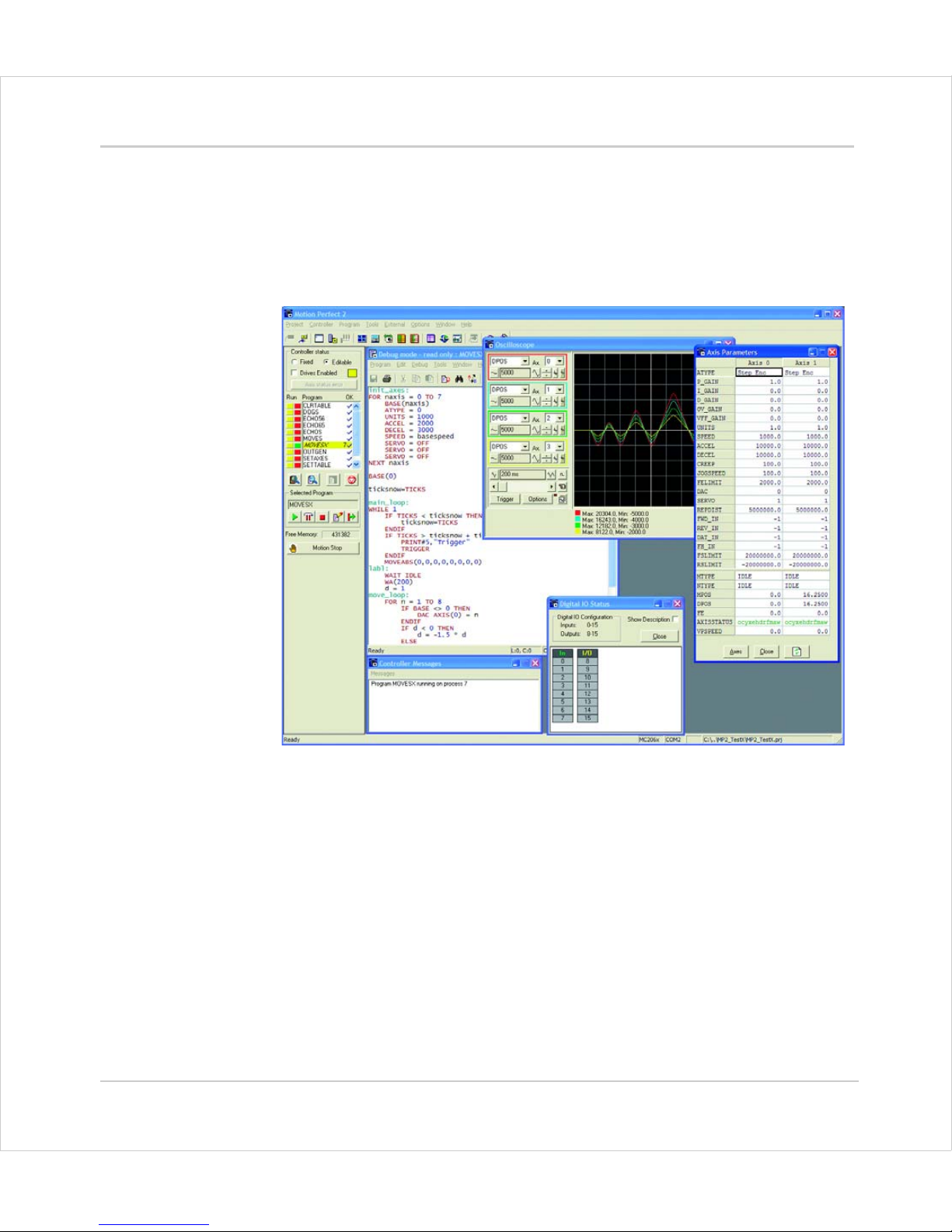
Setup and Programming
To program the
Motion
Coordinator a PC is connected via an RS-232, USB serial or
Ethernet link. The dedicated
Motion
Perfect program is normally used to provide a
wide range of programming facilities, on a PC running Microsoft Windows 2000, XP or
Vista 32bit versions.
Motion Perfect 2
Once connected to the
Motion
Coordinator, the user has direct access to
Trio
BASIC,
which provides an easy, rapid way to develop control programs. All the standard
program constructs are provided; variables, loops, input/output, maths and conditions. Extensions to this basic instruction set exist to permit a wide variety of motion
control facilities, such as single axis moves, synchronized multi axis moves and
unsynchronised multi axis moves as well as the control of the digital I/O.
The
Motion
Coordinator range described in this manual currently consists of the
MC302X, MC206X, Euro 205x, Euro209 an d MC224. The MC464 is not covered he re, but
will be described separately . These controllers feature multi-tasking BASIC. Multip le
Trio
BASIC programs can be constructed and run simultaneously to make program-
ming complex applications m uc h eas ier.
Page 5
Motion Coordinator Technical Reference Manual
Introduction 1-5
Products
Products
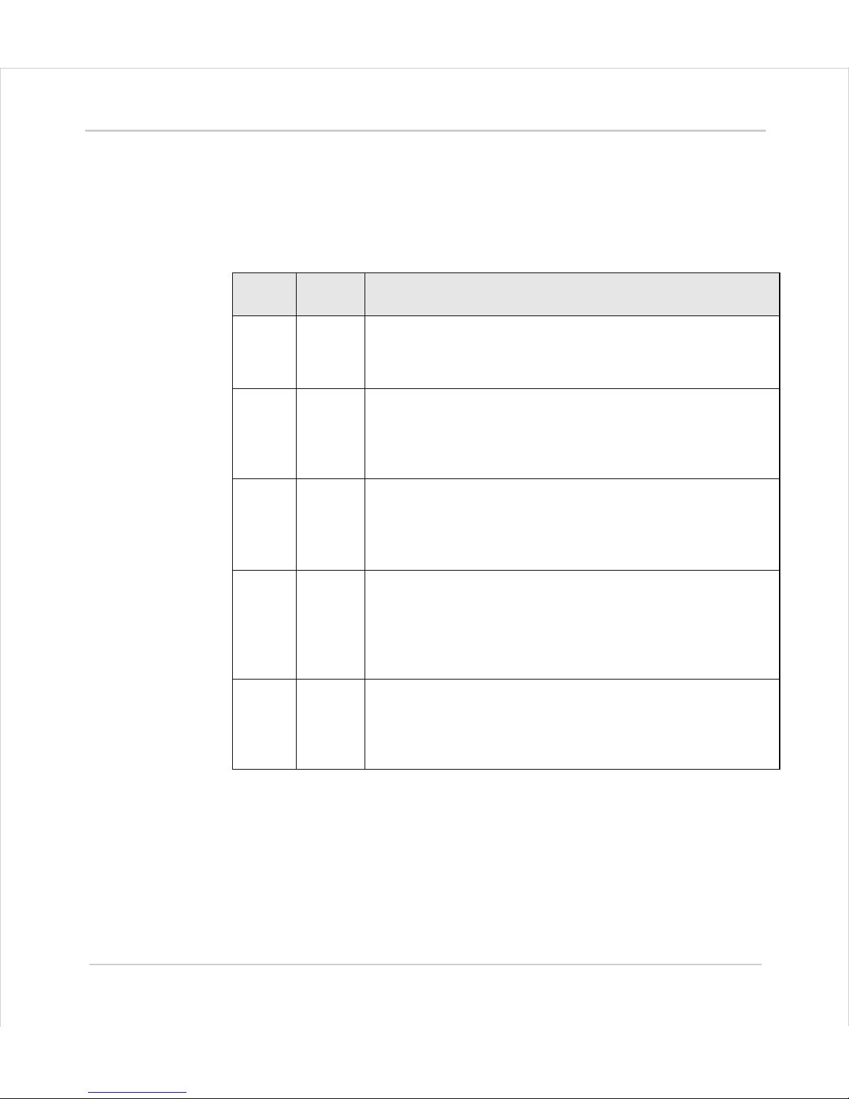
The range of Trio
Motion
Coordinator products covered by this manual:
Motion Coordinator Master Controllers
Product
Code
Name Description
P192 MC302X Compact, low cost DIN-rail mounting module features 1 1/2
servo or 2 stepper axes. 4 Opto-isolated Inputs and 4 Optoisolated I/O channels are built in user serial support RS232/
RS485. Multi-tasking Trio BASIC. I/O CANbus expansion.
P136 MC206X Low cost, high performance DIN-rail mounting controller for 1-8
axes with additional daughter board. 8 Opto-isolated Inputs
and 8 Opto-isolated Input/Output channels,1 Opto-isolated
analogue input, USB and memory stick socket are built in.
Multi-tasking Trio BASIC. I/O CANbus expansion.
P151 Euro
205x
For OEM applications, T rio offer a 3U Eurocard format controller
featuring 4 onboard axes plus the option for a further axis via a
standard Trio daughter board. 16 Opto-isolated Inputs and 8
Opto-isolated Output channels are built in. Multi-tasking Trio
BASIC. I/O CANbus expansion.
P159 Euro 209
For OEM applications, T rio offer a 3U Eurocard format controller
featuring 8 onboard axes plus the option for a further axis via a
standard Trio daughter board. 16 Opto-isolated Inputs and 8
Opto-isolated Output channels are built in. Multi-tasking Trio
BASIC. I/O CANbus expansion. Motion Perfect programming via
Ethernet ports.
P170 MC224 Flexible high performance master controller for 1-24 axes. 8
Opto-isolated Inputs and 8 Opto-isolated Input/Output
channels, 2 Opto-isolated analogue inputs, USB and memory
stick socket are built in. Multi-tasking Trio BASIC. I/O CANbus
expansion.
Page 6
1-6 Introduction
Products
Trio Motion Technology
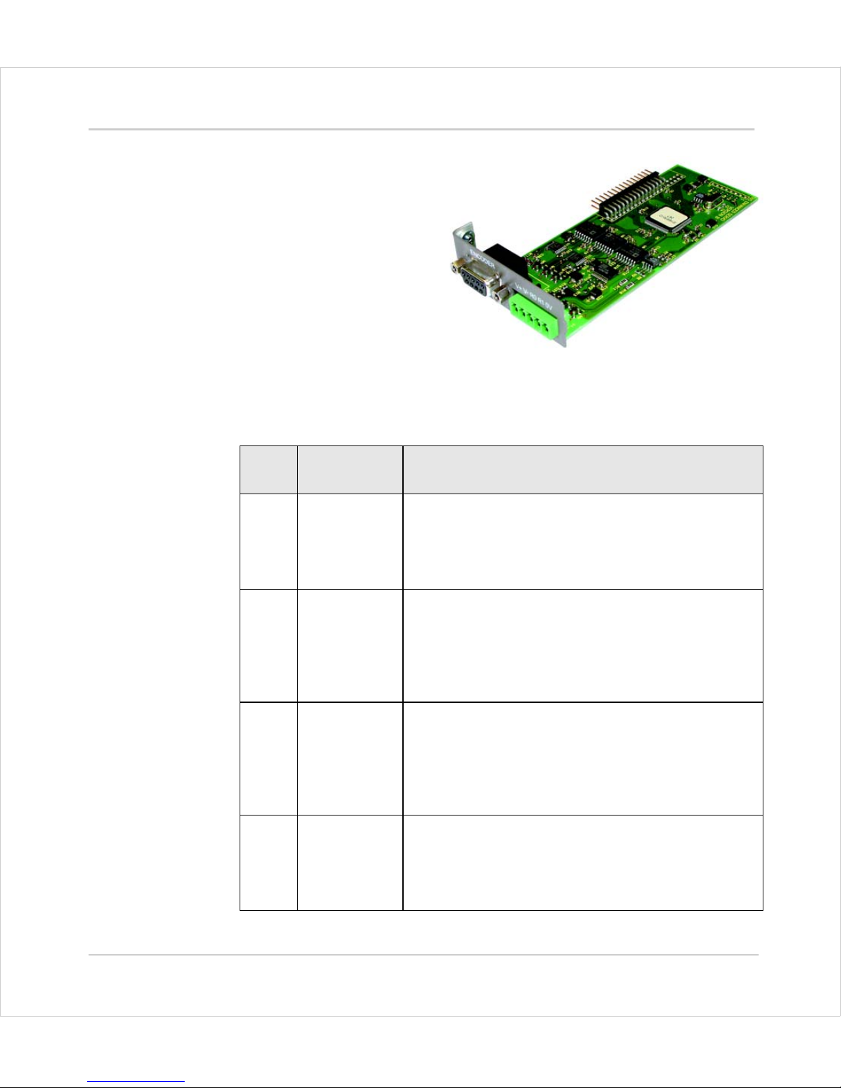
Daughter Boards
The Daughter Board concept is a
one of the key features which
give the
Motion
Coordinator
system enormous flexibility in its
configuration.
The Daughter Boards provide the
interface to many types of S ervo
or Stepper Axes, plus a number
of advanced communications
options as well.
There are 19 types of daughter boards currently available:
Product
Code:
Name Description
P200 /
P201
Servo Encoder +/- 10v Output, Differential Encoder Input
plus Hardware Registration Input
The Servo Encoder daughter board provides the interface to a DC or Brushless servo motor fitted with an
encoder or encoder emulation.
P210 Servo Resolver +/- 10v Output, Resolver Input
plus Hardware Registration Input
The Servo Resolver daughter board provides the interface to a DC or Brushless servo motor fitted with a
resolver. The resolver port provides absolute position
feedback within one motor turn.
P220 Reference
Encoder
Differential Encoder Input
plus Hardware Registration Input
The Encoder daughter board provides an encoder input
without any servo feedback facility for measurement,
registration and synchronization functions on conveyors, drums, flying shears, etc.
P225 Analog Inputs 8 x 0 to 10 Volt Analogue Inputs
The Analog Inputs daughter board has 8 x 16 bit inputs
for use as general analog input channels or as feedback
for up to 8 axes. When used for feedback, the A to D is
synchronised to the SERVO_PERIOD .
Page 7
Motion Coordinator Technical Reference Manual
Introduction 1-7
Products
P230 Stepper Open-collector Step, Direction, Boost and Enable out-
puts
The Stepper daughter board generates pulses to drive
an external stepper motor amplifier. Single step, half
step and micro-stepping drives can be used with the
board.
P240 Stepper
Encoder
Open-collector Step, Direction, Boost and Enable outputs plus Differential Encoder Input.
The Stepper Encoder daughter board with position verification has all the features of the simpler stepper
daughter board. Position verification is added to a
stepper axis by providing encoder feedback to check
the position of the motor.
P242 Hardware
Pswitch
Differential Encoder Input
plus Hardware Position Switch Outputs
The Hardware PSWITCH daughter board allows 4 opencollector outputs to be switched ON and OFF at programmed positions. This function is similar to the
PWITCH command which is implemented in the system
software and allows outputs to be switched ON a nd OFF
over defined position sectors. The Hardware PSWITCH
daughter board performs the position comparison in
electronic hardware on the daughter board. This allows
the pulses generated to be very accurately timed.
P260 Analogue Out-
put
+/- 10v Output with direct DAC control
The Analogue Output daughter board provides a 12 bit
+/-10v voltage output for driving inverters and other
devices. The board is a simplified servo daughter board
and the connections are similar.
P270 SSI Absolute
Servo
+/- 10v Output, Differential Encoder Input
plus Hardware Registration Input
The SSI daughter board provides the interface to a DC
or Brushless servo motor fitted axis with an absolute
encoder using the Synchronous Serial Interface (SSI).
Product
Code:
Name Description
Page 8
1-8 Introduction
Products
Trio Motion Technology
P280 Differential
Stepper
Differential Line Driver outputs for Step, Direction,
Boost and Enable, plus Hardware Registration Input
The Differential Stepper daughter board is a stepper
daughter board with the output signals provided as differential 5 volt signals on a 15 way 'D' connector. The
daughter board does not feature an encoder port for
position verification, but does have a registration input
to allow for capture of the number of step pulses when
a registration signals arrives.
P290 /
P293
CAN Digital Link to CANBus drives
The CAN daughter board provides synchronous control
of up to four axes using the CanOpen protocol. Alternatively, it can be set up as a DeviceNet slave node, or
may use the can directly from Trio Basic.
P291 SERCOS Digital Link to SERCOS drives
The SERCOS daughter board provids digital control to
appropriate servo drives via a Fibre Optic loop. Up to 8
axes can be connected to each P291, which allows the
MC224 to control up to 24 axes.
P292 SLM Digital Link to SLM drives
The SLM daughter board is aimed at providing digital
control channels for servo drives utilising the SLM protocol.
P295 USB Interface Universal Serial bus interface for high-speed PC
communications
The USB daughter board provides a high speed i nterface
between the Euro205x and Euro 209 and a host PC fitted
with a USB port. Support for this high speed interface is
included in Trio's MotionPerfect 2 application and software libraries allow developers to support the interface
within their own programs.
Product
Code:
Name Description
Page 9
Motion Coordinator Technical Reference Manual
Introduction 1-9
Products
Custom Daughter Boards
Trio can produce custom daughter boards for specific customer applications where
required.
P296 Ethernet 10 base-T Ethernet interface for TCP/IP networks
The Ethernet daughter board provides a very high speed
interface between the Motion Coordinator and a host
PC fitted with an Ethernet port. Support for Ethernet is
included in Trio's MotionPerfect 2 applic ation and software libraries allow developers to support the interface
within their own programs. In addition to this, support
for Modbus TCP is included on the board..
P297 Profibus Profibus Fieldbus Interface
With the Profibus Daughter Board and appropriate software on the Motion Coordinator, it is possible to connect to external devices using the Profibus protocol.
P298 Ethernet IP Ethernet IP interface
Adds 1 channel of Ethernet IP server for connection to
PLC’s and other devices supporting Ethernet Common
Industries Protocol (CIP).
Product
Code:
Name Description
Page 10
1-10 Introduction
Products
Trio Motion Technology
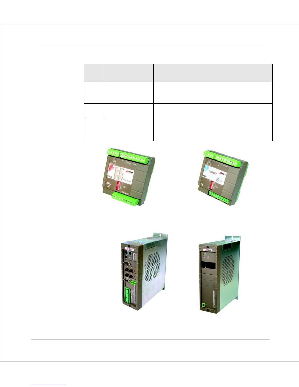
I/O Expansion options
MC224 and the P301 Axis Expander
Prod.
Code
Name Description
P316 CAN 16 IO DIN Rail mounted 24v I/O expander module pro-
vides 16 opto-isolated channels each of which may
be used as an Input or an Output.
P325 CAN Analog Inputs DIN Rail mounted +/- 10v Analog Input module pro-
vides 8 opto-isolated channels.
P301 Axis Expander Expansion module provides housing for up to 4
additional axis daughter boards. Up to 3 connect to
the MC224 and MC224.
P316 - CAN-16 I/O
P325 - CAN-8 Analog Inputs
Page 11
Motion Coordinator Technical Reference Manual
Introduction 1-11
Products
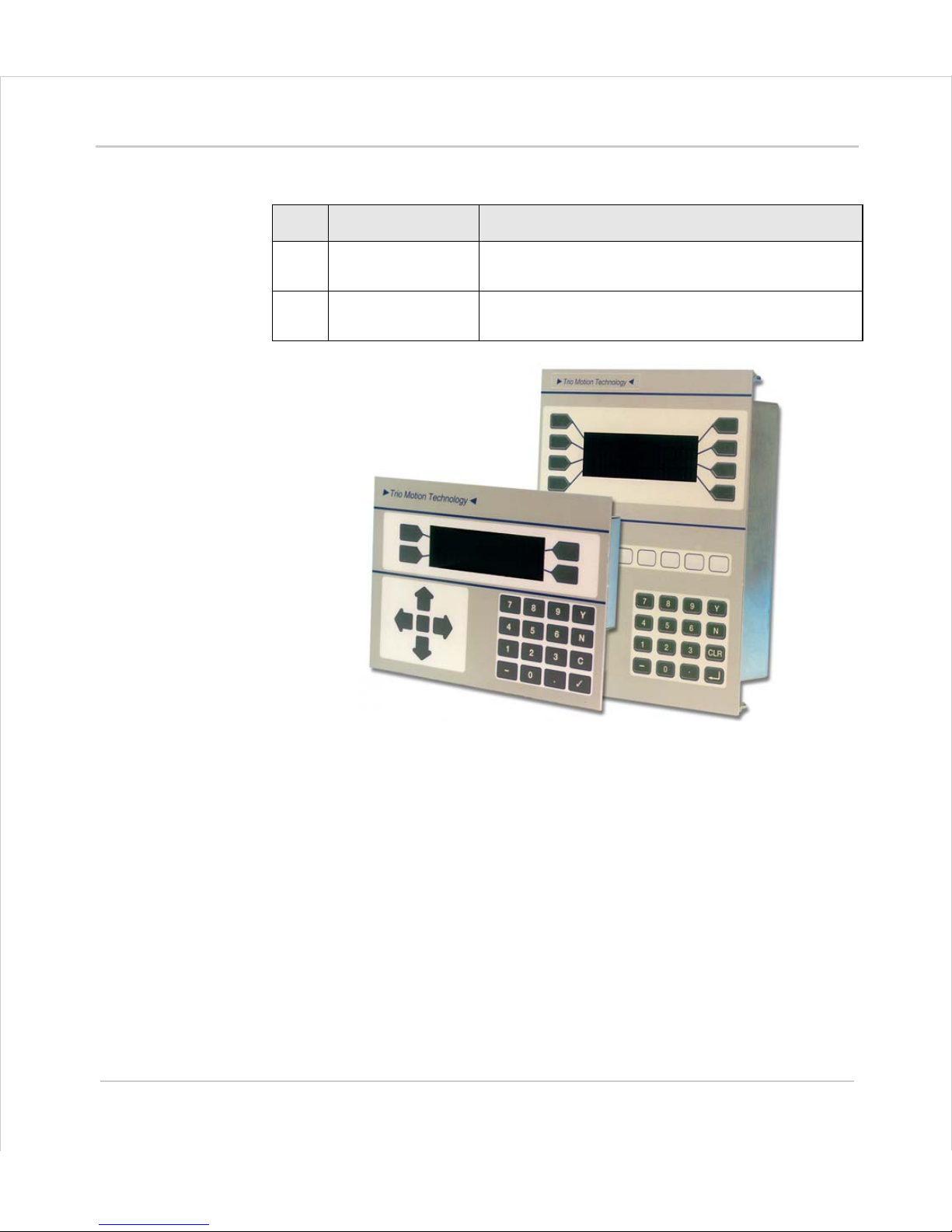
Operator Interfaces
Name Name Description
P502 Mini-Membrane
Keypad
Compact operator keypad/display
P503 Membrane Keypad High performance general purpose operator key-
pad/display
Page 12
1-12 Introduction
System Building
Trio Motion Technology
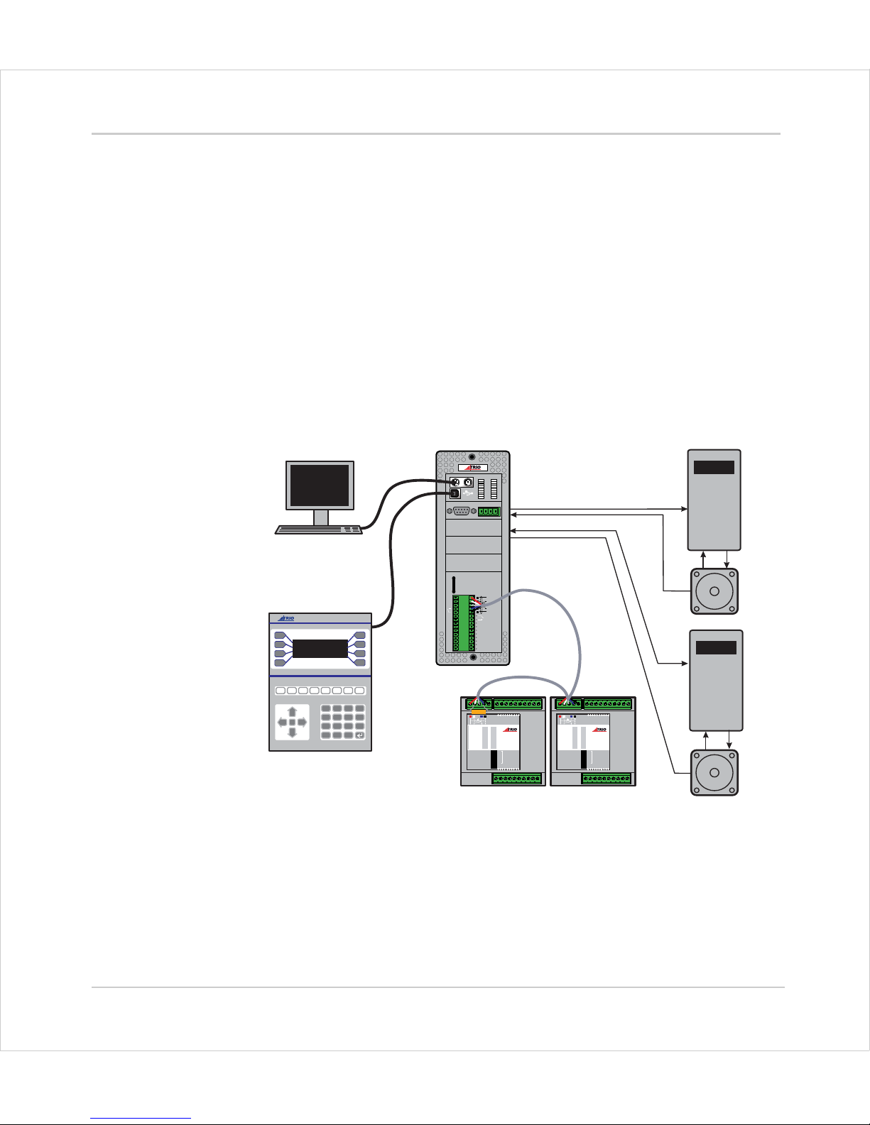
System Building
The modules and boards may be mixed within the system rules:
1) Every system must start with one Motion Coordinator master unit as this contains
the processor and logic power supply for the system.
2) The MC224 master unit can house up to 4 daughter boards. The Euro 205x, Euro
209 and MC206X will accept a single daughter board. These can be of any type.
3) The MC224 can have up to 3 axis expander modules added to house up to 16
daughter boards. 4 being housed in the Master and 4 in each of the axis expanders.
4) Up to 16 CAN-16 I/O and 4 CAN Analog Input modules can be connected to any
Motion Coordinator.
Typical System Configuration
ENCODER
V+ V- R
0v
8
9
10
11
12
13
14
15
0
OK
A
B
STA
1
2
3
4
5
6
7
SERIAL
BAT
5 4 3 2 1
9 8 7 6
MOTION
TECHNOLOGY
IO8
IO9
IO10
IO11
IO12
IO13
IO14
IO15
I 0
I 1
I 2
I 3
I 4
I 5
I 6
I 7
24v
0v
A1
A0
A-
B
0
1
2
3
4
5
6
7
8
9
10
11
12
13
14
15
1
2
4
8
16
32
OFF
MS NS
PR
DR
10 11 12 13 14 15 24v Ov98
765432100v24v
NODE
ADDRESS
CAN16 -I/O
0
1
2
3
4
5
6
7
8
9
10
11
12
13
14
15
1
2
4
8
16
32
OFF
MS NS
PR
DR
10 11 12 13 14 15 24v Ov98
765432100v24v
NODE
ADDRESS
CAN16 -I/O
7
4
1
-
8
5
2
0
9
6
3
.
Y
N
CLR
PC for Programming
Operator Interface
Motion Coordinator
CAN I/O
Servo Drive
Servo Drive
Motor
Motor
MOTION
TECHNOLOGY
MOTION
TECHNOLOGY
MOTION
TECHNOLOGY
Page 13
Motion Coordinator Technical Reference Manual
Introduction 1-13
System Building
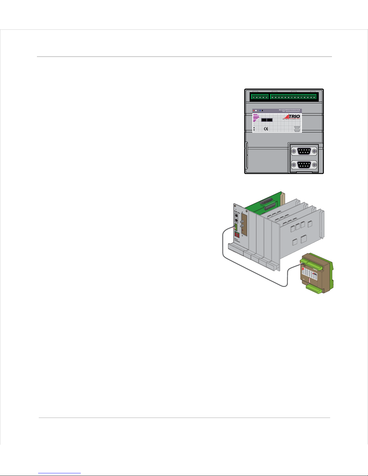
System Examples
Example 1
Simplest Possible System - Single MC302X
• 1½ Axis Servo (Servo + reference encoder)
or 2 Axis Stepper
• 8 Channels of 24v I/O on board
- 4 Inputs
- 4 I/O
Example 2
Euro205x, 5 Axis Rack mounted System
The Euro 205x controller provides a
compact rack-mounted controller ideal
for volume OEM applications.
The four internal axes are configured
as stepper axes and connected via the
backplane to third party stepper
drives.
An optional P200 Servo Daughter Board
provides a fifth axis connected to a
servo drive.
•5 servo axes
• 40 Channels of 24v I/O
- 16 in + 8 out on Euro205x, plus
- 16 I/O on CAN-16 I/O expander
P192
012389101124v0vV+V-
AXIS 0
AXIS 1
SERIAL A
SERIAL B
MC302X
OK STATUS
P
3
1
5
7
6
5
4
3
2
1
0
2
4
v
0
v
C
A
N
1
6-I/
O
M
S
EURO205
CAN-16 I/O
Page 14
1-14 Introduction
System Building
Trio Motion Technology
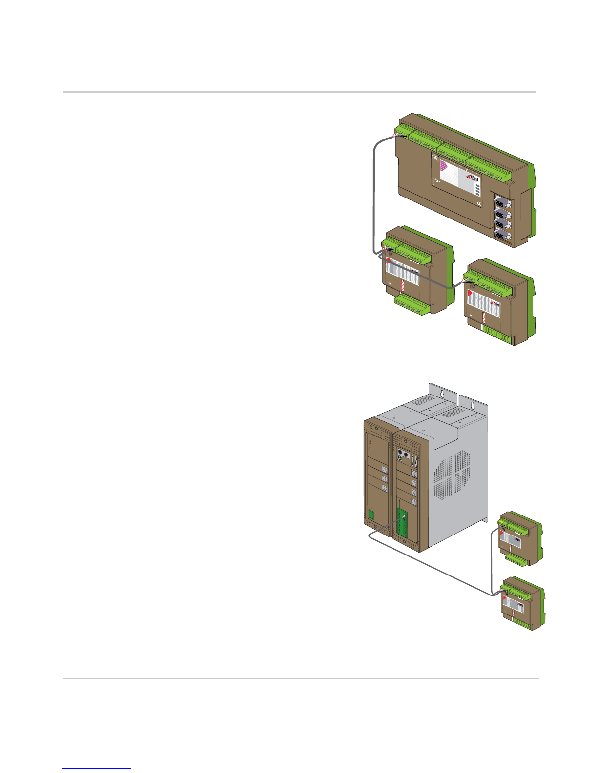
Example 3
MC206X - 5½ Axis Servo System
Utilising the four internal axis as servo
axes, an optional servo daughter board
and the reference encoder input to
provide a total of 5 servo axes plus the
reference (master) encoder.
The MC206X has 16 channels of 24v I/O as
standard, this is expanded up to 32
channels with the addition of a CAN-16 I/O
module. 8 Analog Inputs (+/- 10v) are
provided by the CAN Analog Inputs
module.
• 5 servo / stepper axes
• 32 Channels of 24v I/O
- 8 in + 8 I/O on MC206, plus
- 16 I/O on CAN-16 I/O expander
• 8 Analogue Input Channels
Example 4
MC224 - 7 Axis System
The system comprises an MC224 Master
with and additional three axes in the
optional Axis Expander module. The
axes can be any combination of servo
and stepper drives determined by the
daughter boards used.
The MC224 has 16 channels of 24 v Digital
I/O as standard, this is expanded up to
32 with the addition of a CAN-16 I/O
module. 8 Analog Inputs (+/- 10v) are
provided by the CAN Analog Inputs
module.
•7 axes
- 4 on MC2224 Master, plus
- 3 on Axis Expander
• 32 Channels of 24v I/O
- 8 in + 8 I/O on MC204, plus - 16 I/
O on CAN-16 I/O expander
• 8 Analogue Input Channels
P325
7
6
5
4
3
2
1
0
2
4
v
0
v
C
A
N
A
N
A
L
O
G
IN
P
U
T
S
MS
NS
P
3
1
5
7
6
5
4
3
2
1
0
2
4
v
0
v
CAN 16-I/O
M
S
CAN-16 I/O
Axis 0
Axis 1
Axis 2
Axis 3
S
T
A
T
U
S
O
K
0
1
2
3
4
5
6
7
MC206X
Motion
Coordinator
P
1
3
6
0
v
A
0
1
2
3
4
5
6
70
v
2
4v 89
10
11 12 13
14
15
E-
A
/A
B
/
B
Z
/Z
V-
V0
V1V2 V3
SER
I
AL
A
S
ERI
A
L B
CAN-Analog Inputs
MC206X + Daughter Board
P
3
2
5
7
6
5
4
3
2
1
0
2
4
v
0
v
CAN
ANALOG
INPUTS
M
S
N
S
P
31
5
7
6
5
4
3
2
1
0
24v0v
C
A
N
1
6
I
/
O
M
S
CAN-16 I/O
Axis Expander
MC224 Motion Coordinator
CAN-Analog Inputs
Page 15
Motion Coordinator Technical Reference Manual
Introduction 1-15
System Building
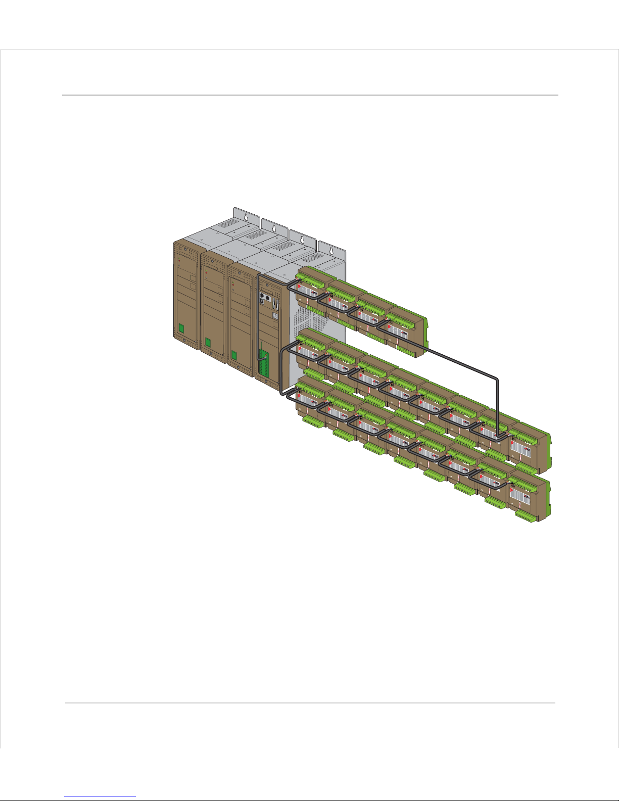
Example 5
MC224 - 16 axis system with maximum I/O expansion
The example system illustrated below shows an MC224 controller with the maximum
possible I/O expansion. Applications for a system of t his c omplexity might include
collating or packaging machinery where there are multiple operations performed on a
product and many I/O are used for sensors etc.
•16 Axes (Any type)
• 272 Channels of 24v I/O
- 8 in + 8 I/O on MC224, plus
- 256 I/O (16 * 16) on the 16 CAN-16 I/O modules
• 32 Analogue Input Channels (8 per module)
P325
7
6
5
4
3
2 1
0
2
4v
0v
CAN
ANALOG
INPUTS
MS
NS
P325
7
6
5
4
32
1
0
24v
0
v
CAN
ANALOG
INPUTS
MS
NS
P325
7
65
4
3
2 1
0
2
4
v
0v
CAN
ANALOG
INPUTS
MS
NS
P325
7
6
5
4
32
1
0
24
v
0v
CAN
ANALOG
INPUTS
MS
NS
P315
7
6
5
4
3
2
1
0
24v
0v
CAN 16-I/O
MS
P315
7
6
5
4
3
2
1
0
24v
0v
CAN 16-I/O
MS
P315
7
6
5
4
3
2
1
0
24v
0v
CAN 16-I/O
MS
P315
7
6
5
4
3
2
1
0
24
v
0v
CAN 16-I/O
MS
P315
7
65
4
3
2
1
0
2
4v
0v
CAN 16-I/O
MS
P315
7
6
5
4
3
2
1
0
24v
0v
CAN 16-I/O
MS
P315
7
6
5
4
3
2
1
0
24v0v
CAN 16-I/O
MS
P315
7
6
5
4
3
2
1
0
24v
0v
CAN 16-I/O
MS
P315
7
65
4
3
2
1
0
24
v
0v
CAN 16-I/O
MS
P315
7
65
4
3
2
1 0
24v
0v
CAN 16-I/O
MS
P315
7
6
5
4
3
2
1
0
2
4
v
0
v
CAN 16-I/O
MS
P315
7
6
5
4
3
2
1
0
24v
0v
CAN 16-I/O
MS
P315
7
65
4
3
2
1
024v
0v
CAN 16-I/O
MS
P315
7
6
5
4
32
1
0
2
4
v0v
CAN 16-I/O
MS
P315
7
6
5
4
3
2
1
0
24v0v
CAN 16-I/O
MS
P315
7
65
4
3
2
1
0
2
4v
0v
CAN 16-I/O
MS
CAN-16 I/O
Axis Expanders
MC224 Motion Coordinator
CAN-Analog Inputs
Page 16

1-16 Introduction
System Building
Trio Motion Technology
F eatures and Typical Applications
Trio
BASIC contains accurate motion control functions for the generation of complex
movements of various types, including:
• Linear interpolation of up to 24 axes
• Circular and helical interpolation
• Variable speed and acceleration profiles
•Electronic gearboxes
• Electronic cam profiles
The operator interface may be achieved by any combination of the followin g:
• Dedicated host computer (connected via USB, Ethernet or RS-232 serial port)
• Membrane Keypad with Vacuum Fluorescent Display
• Dedicated Operator Panel using the’Modbus’ serial protocol.
• Switches / Thumbwheels
•Status lamps
The system is able to control a wide range of mechanisms and equipment including:
• Brushless servo motors
•Stepper motors
• Brushed DC servo motors
• Hydraulic servo valves
• Hydraulic proportional valves
• Pneumatic/hydraulic solenoids
•Relays/contactors
Typical applications:
• Cut to length • Coil winding • Automotive welding
• Flying shears • Laser guidance • Spark erosion
• Glue laying • Electronic assembly • Drilling
• Web control • Printing • Milling
• Tension control • Collating
• Pick & Place • Packaging • YOUR application
Page 17
Motion Coordinator Technical Reference Manual
Introduction 1-17
System Building
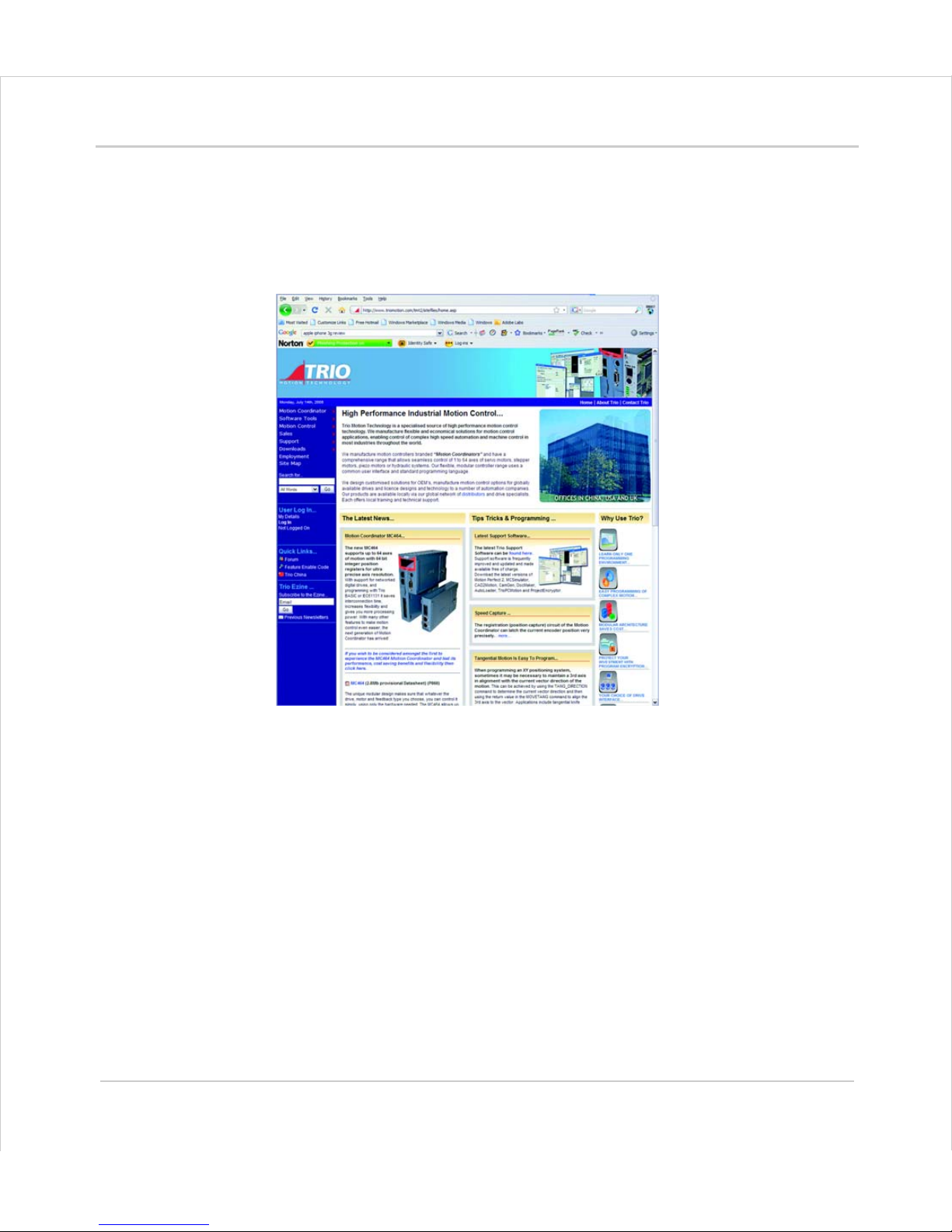
The Trio Motion Technology Website
The Trio website contains up to the minute news, information and support for the
Motion
Coordinator product range.
Website Features
•Latest News
•Product Information
• Manuals
• Support Software
• System Software Updates
• Technical Support
• User’s Forum
• Application Examples
• Employment Opportunities
WWW.TRIOMOTION.COM
Page 18

1-18 Introduction
System Building
Trio Motion Technology
 Loading...