

Page 1
• WARRANTY SERVICE CARD
WARRANTY CARD
PRODUCT NAME Wireless Transceiver System PERIOD
MODEL NAME CCR24GEN
PURCHASE DATE . . 200_
WARRANTY PERIOD . . 200_
CUSTOMER’S ADDRESS : NAME :
TEL :
AGENT’S ADDRESS : NAME :
TEL :
* Be sure to fill in blanks when the unit is sold
We grant 1 year warranty on the product commencing on the
date of purchase. Within the warranty period, the manufacturer
will correct, free of charge, any defect in the unit resul t ingfrom
faults in materials or workmanship, either by repairing or
replacing the entire unit as manufacturer may choose.
This warranty does not cover: damages due to improper use,
normal wear and tear, or defects that have a negligible effect on
the value or operation of the unit. The warranty is void if repairs
are undertaken by unauthorized persons and if original Trinus
parts are not used.
To obtain service within the warranty period, bring in or ship the
complete unit with your purchase invoice to a Trinus Customer
Service Center.
1 YEAR
From the
date of
purchase.
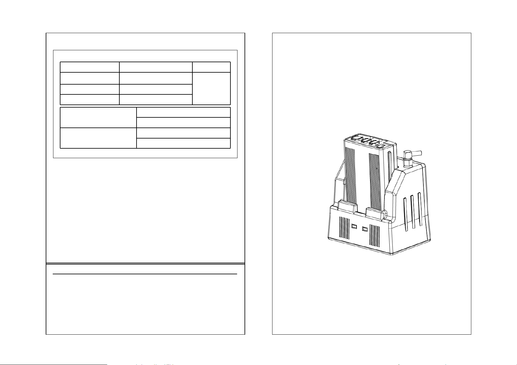
CCR24T
CCR24R
WIRELESS TRANSMITTER SYSTEM
User’s Guide
● Read this user’s guide carefully for safe operation and proper
use of the product .
Page 2
WARNING
* Please turn off the power before connecting or
disconnecting any cables.
- Do not immerse in water or keep in humid areas
- Do not place near TV, speakers, or other electronic devices
- Before installation, check power supply and voltage to avoid
hazards
- Do not apply force or shock to the unit
- Do not disassemble the unit
TECHNICAL SPECIFICATIONS
Operating Voltage TX: 3.7VDC RX: 12VDC
Frequency Range 2401.056 MHz ~ 2478.816 MHz
MEMO
Operating Range Up to 1500 feet at the open field
Operating Temperature 10 ~ 110 °F
LED Indicators TX: low battery warning, Out of Range,
Jacks 8 pin RJ-45 for power, audio out, and
Battery Capacity: Lithium-Li-Polymer 3.7V
* Note : Operating Range can be different
according to the environment
Talk On, Mute
RX: Charging indicator, Talk On
trigger out
DC/1400mA
Charging time: 3 hours
Talk Time: Max. 13 Hours
Page 3
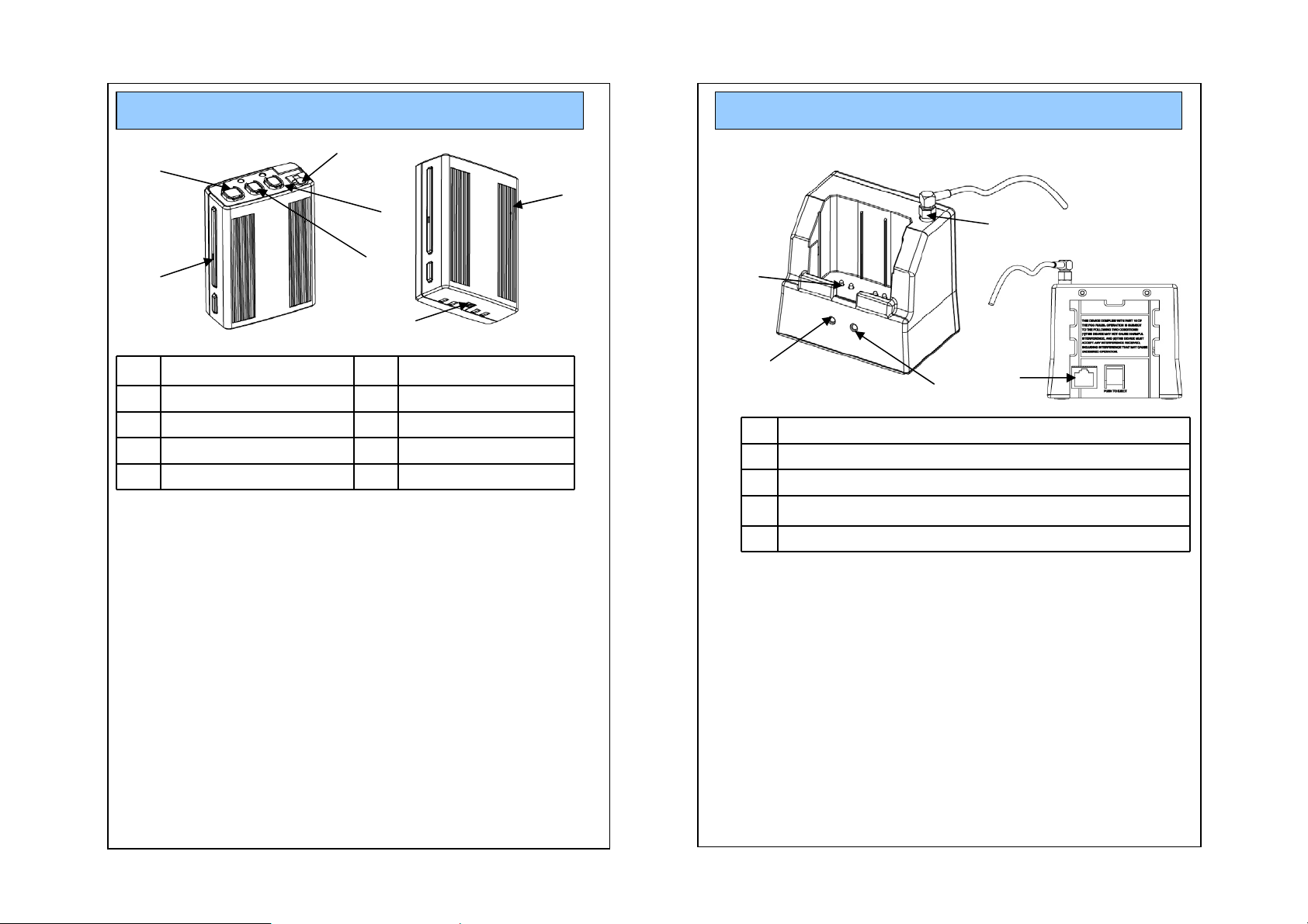
OPERATION (TX)
1
OPERATION (Cradle)
5
6
4
1
3
2
7
1
REC,TALK On/Off
2 BEEP 7 Power On/Off
3MODE
4MUTE ON/FF
5 Microphone Jack
6 Internal MIC
1. REC On/Off button
* LED : REC & Talk On/Off – Green LED On/Off
Mute On – Green LED blinking
Low Battery – Red LED blinking
Out of Range – Red LED steady On
2. Beep: Beep Tone
3. Mode: Beep > Vibration > Beep + Vibration > NO action
Every time you push the button, mode will be automatically
changed in order. (This Function operate only at St-by mode)
4. Mute On/Off:
When user want to mute the voice in the Communication.
Press the button to mute and press the button again to not-mute.
5. Microphone Jack (* Lapel MIC is optional)
6. Internal MIC
7. Power On/Off: Turn on/off the power of unit. When this is turned
off, Unit will not work.
4
2
3
1 Antenna connection (external Antenna)
2 LED : Recording ON/OFF, ID Matching
3 LED : Battery Charging Status
4Charging PIN
5 RJ-45 Jack
5
1. Antenna Connection
2. LED : REC & TALK On/Off – Green LED On/Off
ID Matching On – Green LED blinking
3. LED : Battery Charging – Red LED on
Battery is fully charged – Green LED on
4. Charging Pin
5. RJ45 Jack for the cable
Page 4
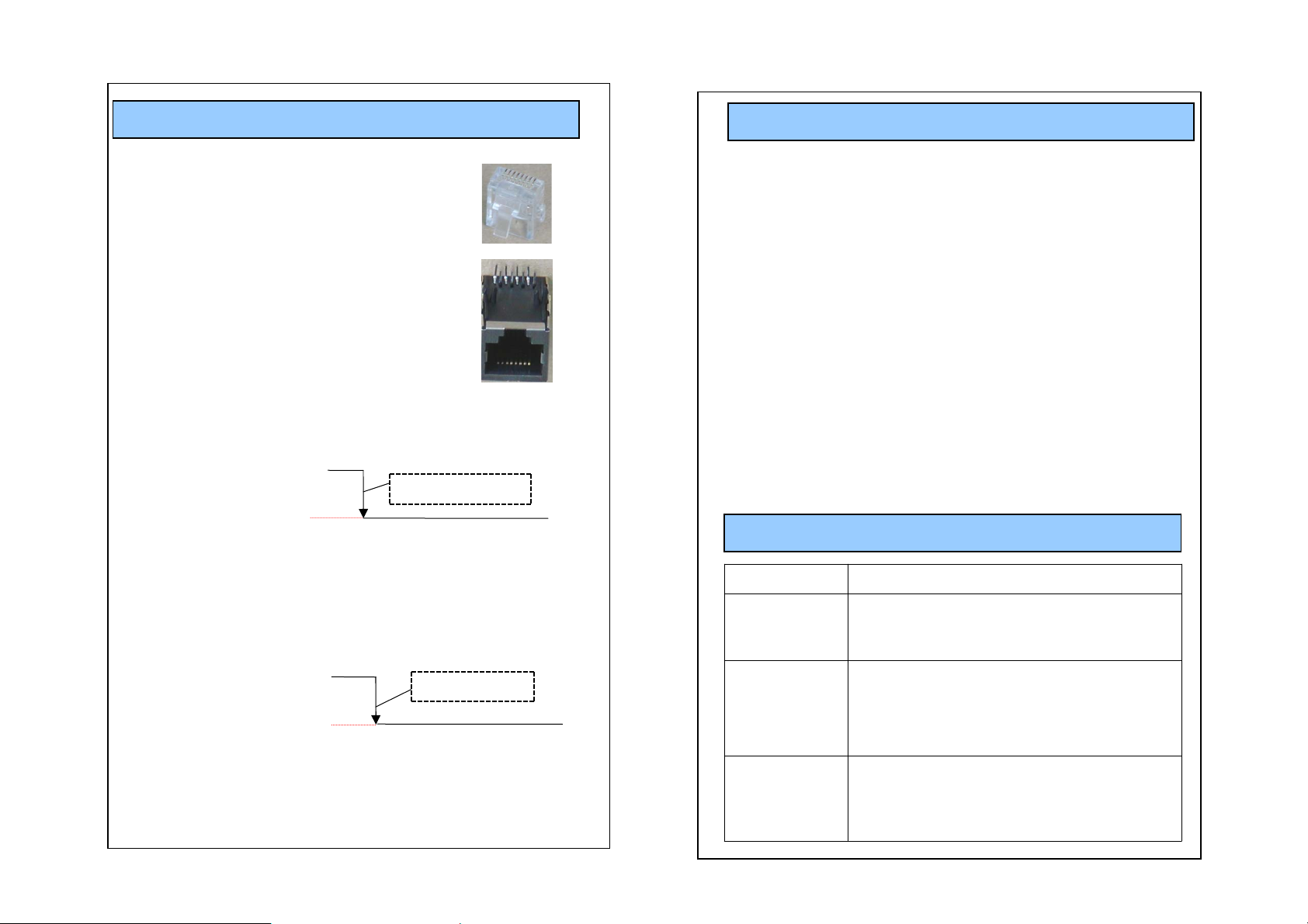
PIN DESCRIPTION
FUNCTIONS
RJ-45 Connector Pin Description
Pin# 1: VCC, DC power (10V ~ 16VDC)
Pin# 2: GND
Pin# 3: Audio Signal
Pin# 4: Audio Signal GND
Pin# 5: GND
Pin# 6: 2.8V out when the unit is on. Short this pin
to GND to remotely turn on TX.
Normal “H” 5.0V
Recording starts
0V
Pin# 7 : 0V when TX is ON, 5V when TX is OFF.
Use this pin for recording trigger (Recording Trig ger)
8
1
18
- 95 Channel Possible in the 2400~2483MHz Bandwidth
- Transmission Range up to 1500 feet in open field
- Audible and LED indicator out of range warning.
- Better voice quality.
- 40 bits security code combination.
- Charger Status Indicator
- Mute function On/Off Key (Transmitter)
- Auto link (When the system On/Off is On mode)
- Recorder On/Off Switch
- Transmitter Power On/Off switch
- Low Battery Indicator (Transmitter)
- Link LED indicator (Receiver & Transmitter)
- Beep Mode and Vibration Mode Selectable for user’s convenience
TROUBLESHOOTING
Problems Check Points
- Check the battery status
No reception
- Check the connection and cables
- Check the communication range
Normal “H” 5.0V
0V
Pin# 8 : FULL UP 5V 470 OHM
TX unit is on
Poor reception,
static, noise
Unit does not
respond
- Change the location of RX Set
- Check the communication range
- Check to see if unit is placed near TV,
speakers, or other electronic devices
- Check the battery status
- Check the power switch on the bottom of
the unit
- Check the connection and cables
Page 5

Safety Approval
- FCC ID: R OYCCR24R / ROYCCR24T
This device complies with Part15 of the FCC Rules.
Operation is subject to the following two conditions :
- Reorient or relocate the receiving antenna.
- Increase the separation between the equipment and receiver.
- Connect the equipment into an outlet on a circuit different
from that to which the receiver is connected.
(1) This device may not cause harmful interference, and
(2) This device must accept any interference received, including
interference that may cause undesired operation.
CAUTION : Changes or modifications not expressly approved by the
party responsible for compliance could void the user s authority to
operate this device.
This equipment has been tested and found to comply with the limits
for a Class B digital device, pursuant to part 15 of the FCC Rules.
These limits are designed to provide reasonable protection against
harmful interference in a residential
installation. This equipment generates, uses and can radiate radio
frequency energy, and, if not installed and used in accordance with
the instructions, may cause harmful interference to radio
communications. However, there is no guarantee that interference
will not occur in a particular installation. If this equipment does cause
harmful interference to radio or television reception, which can be
determined by turning the equipment off and on, the user is
encouraged to try to correct the interference by one or more of the
following measures:
- Consult the dealer or an experienced radio/TV technician for
help.
FCC RF Radiation Exposure Sta tement
This equipment complies with FCC RF radiation exposure limits
set forth for an uncontrolled environment. This equipment
should be installed and operated with a minimum distance of 20
centimeters between the radiator and your body .
This transmitter must not be co-located or operated in
conjunction with any other antenna or transmitter.
 Loading...