

Page 1
WIRELESS TRANSCEIVER SYSTEM
User Guide :: CCR24PNA
User Guide:CCR24PNA
---------------------------------------------------------
•Read this user guide carefully for safe operation and proper use of the product.
•Features and specifications are subject to change without notification.
1
Page 2

Safety Approval
FCC ID: ROYCCR24PNAR
ROYCCR24PNAT
This device complies with Part 15 of the FCC Rules.
Operation is subject to the following two conditions :
(1) This device may not cause harmful interference, and
(2) This device must accept any interference received, including interference that
may cause undesired operation.
CAUTION : Changes or modifications not expressly approved by the party
responsible for compliance could void the user s authority to operate this
device.
This equipment has been tested and found to comply with the limits for a Class B
digital device, pursuant to part 15 of the FCC Rules. These limits are designed
to provide reasonable protection against harmful interference in a residential
installation. This equipment generates, uses and can radiate radio frequency
energy, and, if not installed and used in accordance with the instructions, may
cause harmful interference to radio communications. However, there is no
guarantee that interference will not occur in a particular installation. If this
equipment does cause harmful interference to radio or television reception,
which can be determined by turning the equipment off and on, theuser is
encouraged to try to correct the interference by one or more of the following
measures:
- Reorient or relocate the receiving antenna.
- Increase the separation between the equipment and receiver.
- Connect the equipment into an outlet on a circuit different from that to which the
receiver is connected.
- Consult the dealer or an experienced radio/TV technician for help.
FCC RF Radiation Exposure Statement
This equipment complies with FCC RF radiation exposure limits set forth for an
uncontrolled environment. This equipment should be installed and operated
with a minimum distance of 20 centimeters between the radiator and your
body. This transmitter must not be co-located or operated in conjunction with
any other antenna or transmitter.
14
Page 3

Safety Approval
Industry Canada
IC ID: 5479A-CCR24PNAR
5479A-CCR24PNAT
Operation is subject to the following two conditions:
(1) This device may not cause interference and
(2) This device must accept any interference, including interference that may cause
undesired operation of the device.
The term “IC:” before the certification/registration number only signifies that registration
was performed based on a Declaration of Conformity indicating that Industry Canada
technical specifications were met.
It does not imply that Industry Canada approved the equipment.
15
Page 4

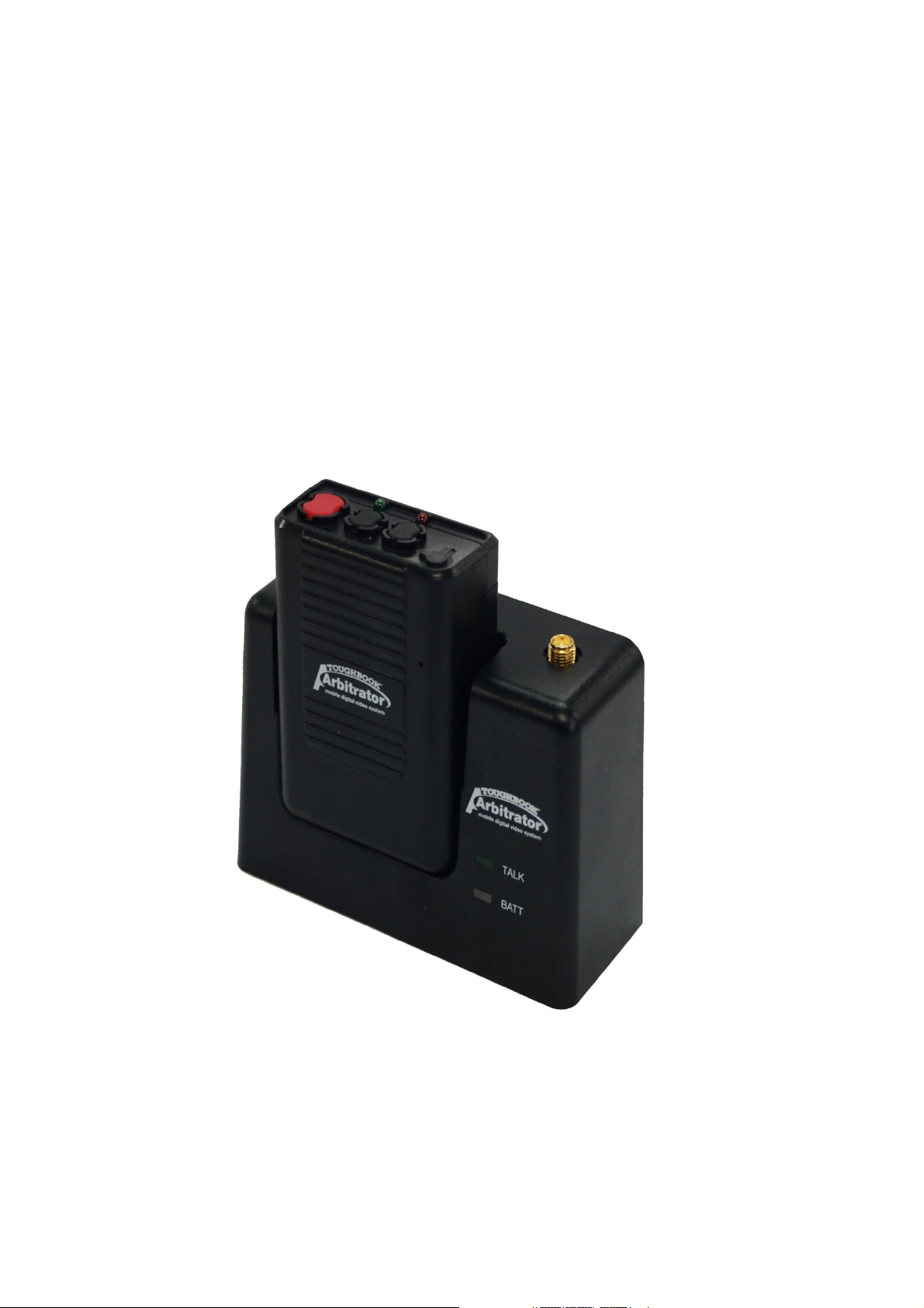
BOX CONTENTS
• 1. Transmitter (TX)
• 2. Receiver (RX)
• 3. Plug-In Microphone (MONO)
• 4. Mounting Bracket for Receiver with
screws
• 5. Rechargeable Li-Ion Polymer
Battery
• 6. Leather Pouch
• 7. External antenna
• 8. Desktop charger for transmitter
• 9. AC Power supply for desktop
charger
• 10. Charger Stand for Desktop Charger
• 11. RF Main Cable
• 12. In-car MIC
• 13. User Guide
2
Page 5
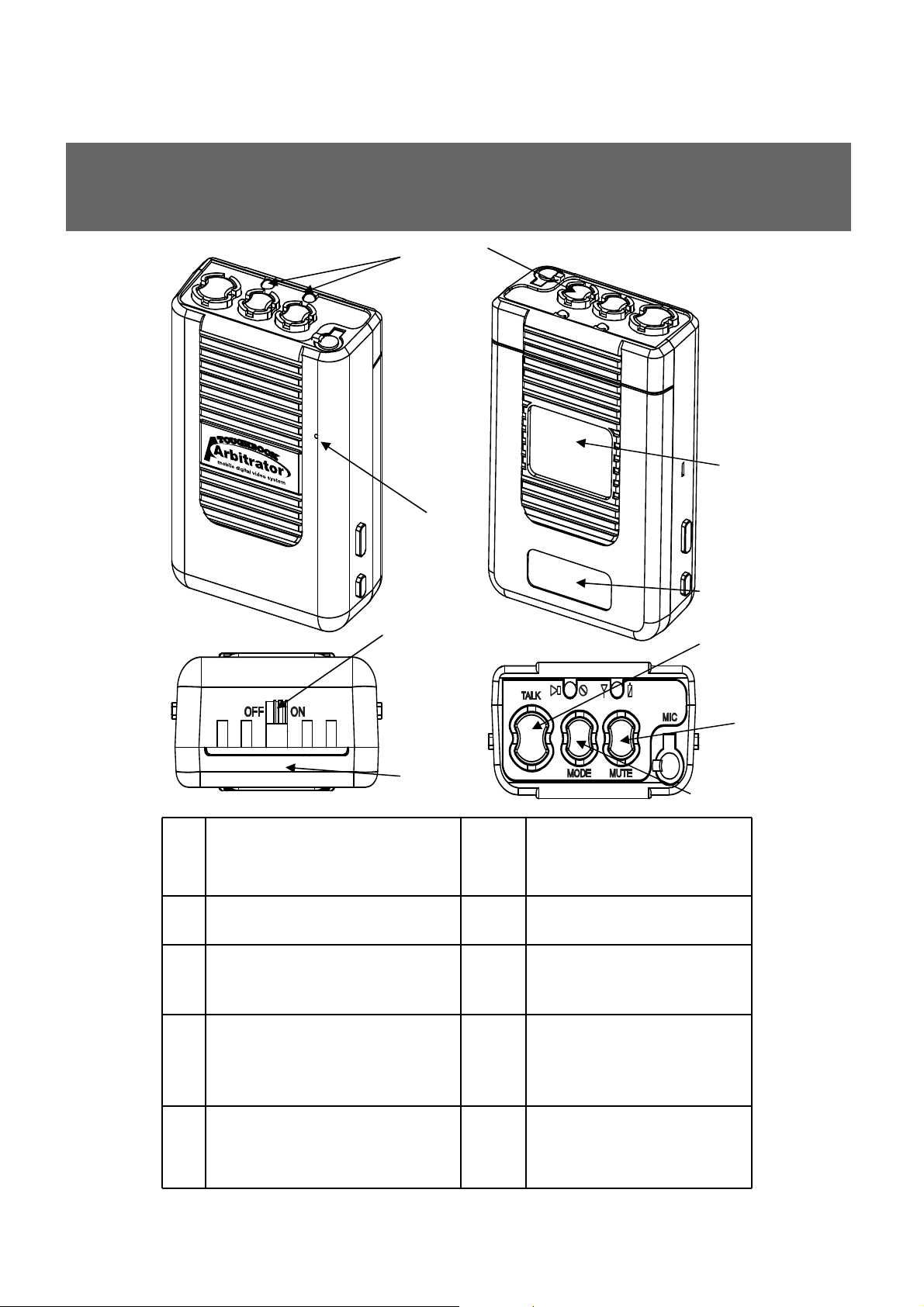
DESCRIPTION - Transmitter
6
1
3
4
2
5
9
7
10
1 LED Indication 6 TX Power
On/Off
2 Built in MIC 7 Battery Cover
3 Microphone Jack 8 Mute Button
4 FCC , IC , cULus
9 Talk Button
Labels
5 Serial Number
Label
10 Mode Selection
Button
8
3
Page 6
DESCRIPTION - Receiver
4
1
6
2
3
5
1 Antenna connection 5 Serial Number Label
2 Talk On (Green LED) 6 Main Cable Connection
3 Battery Charger Status
7 FCC , cULus , IC Labels
(Green + Red LED)
4 Charging PIN/Matching
ID
#2 Talk On LED
#3 Charging Status
7
When TX triggers the
recording of the system ,
Green LED light on
Red LED-In Charging
4
Green LED-Fully charged
Page 7

DESCRIPTION – Receiver LED function
When TX is docked in RX
If completed ID setting – RX “TALK” L
ED once blinking
If uncompleted ID setting –LED
blinking at TX,RX TALK LED
After ID setting , turn off RX “TALK”
LED
When TX is docked in RX
RX LED indicate TX’s power status.
GREEN LED on RX “TALK” LED
blinking- TX off status, in charging
GREEN LED off on RX “TALK” LEDTX power on
AUDIO recording indication
RX “TALK” LED OFF- none AUDIO
recording
RX “TALK” LED GREEN – AUDIO
recording.
BATTERY charging indication
RX “BATT” LED RED- in charging
RX “BATT” LED GREEN- fully charged
If indicate GREEN LED on RX “BATT”
LED, it prevents overcharging by
removing current.
5
Page 8

DESCRIPTION – Control Reference Guide
Transmitter (TX) with
Receiver (RX)
Top of Transmitter(TX)
Internal
Mic
TALK Button
Press for REC
“REC”, “Mute”
Indication Green
LED
MODE
Selection
Button
“Low Battery”, “Out of
Range”,
“Mute” indication Red
LED
Lapel
Mute
Button
Mic
Input
[TALK]
Green LED ON/OFF: REC ON/OFF
Green LED Blinking: ID Matching
(Synch) ON
[BATT]
Red: In Charging
Green: Fully charged
Bottom of Transmitter(TX)
Power
ON/OFF
Button
6
Page 9

OPERATION
- Install the mounting bracket by using the screws
- Slide RX Set onto the Bracket
- Connect the main cable to RX Set
- Connect external antenna to the RX Set.
- Assemble the battery pack into TX Set
- How to change battery pack
-Separate battery cover as shown next picture.
- Separate battery pack with connector.
- Assemble the new battery pack into TX set.
-Assemble battery cover as initial.
- Before using, battery cover should be assembled completely.
- Charge TX set in the RX set for at least 3 hours (when turn off)
- Switch the power ON (located on the bottom of TX unit)
- Place TX on RX to sync the code
7
Page 10

OPERATION
• Indication of LED Button
Mode
LED+
Vibration
Vibration
TALK REC
V(1 time
only)
Green
On
Green
Blink
V(1 time
LED
OFF
only)
LED OFF
Low
Battery
V(1 time
per
second)
Red Blink Red On
V (1 time
per second)
LED OFF
Out of
Range
V(2 times
per
3seconds)
V (2 times
per 3
seconds)
TALK (REC
OFF):
Green ON
REC:
Green Blink
LED OFF
Mute
V(1 time per
5seconds
TALK: Green
ON & Red
Fast Blink
REC: Green
Blink & Red
Fast Blink
V (1 time per 5
seconds)
LED OFF
No
Vibration
No
LED OFF (Green OFF , Red OFF)
No Vibration
LED
Note:1. LED ON: this mode as initial when Power on .
2. After synchronized, the mode goes back to the last.
3. When TX is Off and inserted to RX, there will be no
synchronization.
8
Page 11

DESCRIPTION – Main Cable
1A In-Line fuse
To Receiver
# Important
-These three ground wires have to be all connected together
- Power ground wire from CCR24PNA, Trigger ground wire from CCR24PNA,and Ground
wire of the Recorder GPIO.
Connection with the system
- Power DC12V (Red), Power GND (Black): Power Cables to engine battery.
- Audio Out (RCA Connector) : Connects to “AUDIO IN” port in the back of
recorder.
- Trigger REC (Brown): Connect to GPIO cable.
- Trigger GND (Black): Connect to GPIO black
cable.
9
Page 12

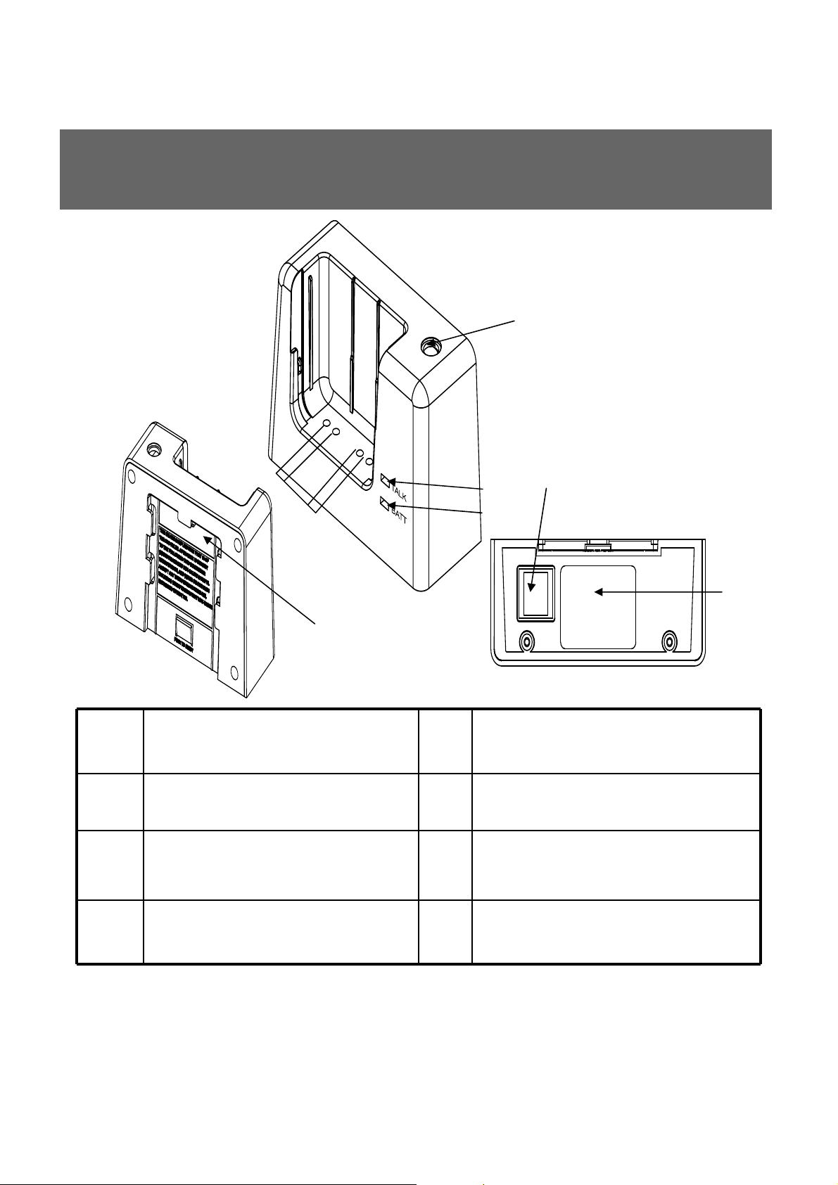
DESCRIPTION – Desktop Charger
* Battery LED : In Charging – Red LED
Fully Charged – Green LED (4V ~ 4.2V)
(Note) Place TX on the charger at least 4.5sec for the
initializing.
Installation for Charger Stand
Charger Stand
TIP1 How to undock TX from RX and Home Charger
To prevent units from being broken by the
improper use, undock TX unit from RX unit
as the drawing described on the right
picture.
10
Page 13

RECOMMENDATIONS
- Prior to use, charge TX at least 3 hours
- Disconnect the battery or switch the power OFF. when TX Set is not in
use for long periods
- Charge TX Set when not in use for short periods
TROUBLESHOOTING
Problems Check points
No reception, - Check the battery status
- Check the connection and cables
- Check the communication range
Poor
reception,
static, noise
Unit does
not respond
TIP2 Preserving the Batteries
To maintain the optimum capacity of the pack, the unit has to be fully
discharged (by using) approximately every 6 months. Then recharge the
battery to full capacity again.
- Change the location of RX Set
- Check the communication range
- Check to see if unit is placed near TV, speakers, or
other electronic devices
- Check the battery status
- Check the power switch on the bottom of the unit
- Check the connection and cables
11
Page 14

SPECIFICATION
Power DC 12V for RX
Frequency
(MHz)
Number of
Channel
Channel Space 864 KHz
Speech Coder 32Kbps ADPCM with Parity
Type of
Modulation
Data Rate 576Kbps Time Division Duplex
Receiver
Sensitivity
Power
consumption
2.4GHz FHSS with 2,401.056 ~ 2,478.816MHz
91Channels
GFSK MODULATION / DEMODULATION
Min : -90 dBm
Typ.: -92 dBm to -94 dBm @BER = 0.001
Max : -96 dBm
TX docks with RX: Nor 550mA , Max 610mA
RX under communication w/TX : Max 120mA
TX under communication w/RX : Max 150mA
Battery Talking Time : 12Hours
Charging Time : 3Hours
Battery Capacity Lithium-ion Polymer 3.7V DC/1300mA (only for Piloting
lot)
TX Power Levels Less than 260 mW
Temperature
Range
Dimensions
(WxDxH)
0°C ~ 50°C
TX : 53mm x 25mm x 72.5mm
RX : 100.5mm x 38.5mm x 67.5mm
12
Page 15

SPECIFICATION
SC14435 2G4HZ Frequency hopping
The number of used frequencies (NUF) in the hopping algorithm is 95.
In base and handset a Primary Hopping lndex Number (PHIN) exist.
This number is incremented modulo NUF in the end of the normal downlink
half-frame. It is broadcast in Q0 message instead of PSCN.
To a simplex or established duplex bearer a Hopping Index Offset (HIO) is
assigned, which is an analogue to the used RF carrier in a FDMA system. This
value is broadcast in place of CN in Q0 message. In the base in all unable
slots in up-link direction the receiver is scanning with HIO=0. the receiver is
scanning with doesn’t exclude RF-carriers.
Different base use different hopping sequences. The different sequences are
derived from the hopping table by adding an offset, SeQuenceCode(SQC).
A hopping table maps an index I to a carrier number: CN = f(I)
The physical RF carrier is calculated by the formula:
CN = (f ((PHIN+HIO) mod NUF) +SQC )mod NUF for 10.368000 MHz crystal
frequencies are derived as: Frequency : 2401.056 MHz + CN*0.864000 MHz
Fast Frequency Hopping : (DCT 2G4) , up to 800 hops/sec
This equipment is made for report by two-way radio in place of business.
13
Page 16

CAUTION
• Li-Ion Battery Safety Precautions (sample document)
• 1. When Using the Battery
• Danger
• (1) Misusing the battery may cause the battery to get hot, explode,
or ignite and cause DANGER serious injury.
• Be sure to follow the safety rules listed below:
• . Do not place the battery in fire or heat the battery.
• . Do not install the battery backwards so that the polarity is reverse
d.
• . Do not connect the positive terminal and the negative terminal of
the battery to each other with any metal object (such as wire).
• . Do not carry or store the batteries together with necklaces, hairpi
ns, or other metal objects.
• . Do not penetrate the battery with nails, strike the battery with a ha
mmer, step on the battery, or otherwise subject it to strong impacts
or shocks.
• . Do not solder directly onto the battery.
• . Do not expose the battery to water or salt water, or allow the batt
ery to get wet.
• (2) Do not disassemble or modify the battery. The battery contains
safety and protection devices which, if damaged, may cause the b
attery to generate heat, explode or ignite.
• (3) Do not place the battery on or near fires, stoves, or other hightemperature locations. Do not place the battery in direct sunshine,
or use or store the battery inside cars in hot weather. Doing somay
cause the battery to generate heat, explode, or ignite. Using the ba
ttery in this manner may also result in a loss of performance and a
shortened life expectancy.
• (4) Do not insert the battery into equipment designed to be hermeti
cally sealed. In some cases hydrogen or oxygen may be discharge
d from the cell which may result in rupture, fire or explosion.
• Warning
• (1) Immediately discontinue use of the battery if, while using, charg
ing, or storing the battery, the battery emits an unusual smell,feels
hot, changes color, changes shape
14
Page 17

CAUTION
• or appears abnormal in any other way. Contact your sales location
or Panasonic if any of these problems are observed.
• (2) Do not place the batteries in microwave ovens, high-pressure c
ontainers, or on induction cookware.
• (3) In the event that the battery leaks and the fluid gets into one’s e
ye, do not rub the eye. Rinse well with water and immediately seek
medical care. If left untreated the battery fluid could cause damage
to the eye.
• Caution
• (1) If the device is to be used by small children, the caregiver shoul
d explain the contents of the user’s manual to the children. The car
egiver should provide adequate supervision to insure that the devic
e is being used as explained in the user’s manual.
• (2) When the battery is worn out, insulate the terminals with adhesi
ve tape or similar materials before disposal.
•Danger
• Be sure to follow the rules listed below while charging the battery.
Failure to do so may cause the battery to become hot, explode, or
ignite and cause serious injury.
•·When charging the battery, either use a specified battery charger
or otherwise insure that the battery charging conditions specified b
y Panasonic are met.
•·Do not attach the batteries to a power supply plug or directly to a
car's cigarette lighter.
•·Do not place the batteries in or near fire, or into direct sunlight. W
hen the battery becomes hot, the built-in safety equipment is activ
ated, preventing the battery from charging further, and heating the
battery can destroy the safety equipment and can cause additional
heating, breaking, or ignition of the battery.
• Warning
• Do not continue charging the battery if it does not recharge within t
he specified charging time. Doing so may cause the battery to bec
ome hot, explode, or ignite.
• Risk of explosion if battery is replaced by an incorrect type.
• Dispose of used batteries according to the instructions.
15
Page 18

CAUTION
• 2. While Charging
• Caution
• The temperature range over which the battery can be charged is 10
°C to 45°C. Charging the battery at temperatures outside of this ran
ge may cause the battery to become hot or to break. Charging the
battery outside of this temperature range may also harm the perfor
mance of the battery or reduce the battery’s expectancy.
• 3. When Discharging the Battery
• Danger
• Do not discharge the battery using any device except for the specif
ied device. When the battery is used in devices aside from the spe
cified device it may damage the performance of the battery or redu
ce its life expectancy, and if the device causes an abnormal curren
t to flow, it may cause the battery to become hot, explode, or ignit
e and cause serious injury.
• Caution
• The temperature range over which the battery can be discharged is
-10°C to 60°C. Use of the battery outside of this temperature range
may damage the performance of the battery or may reduce its lifee
xpectancy.
16
 Loading...