

Page 1

I
Operation Manual
LCR Meter
TX7410
DAE KWANG T&M CO.,LTD
http://www.kdk.co.kr
TEL :02)2617-0787
Page 2

II
Content
CHAPTER 1 GENERAL INTRODUCTION ...................................................................................... 1
1.1 FOREWORD ...................................................................................................................................... 1
1.2 OPER ATIN G CONDITIONS ................................................................................................................. 2
1.2.1 Power requirements ..................................................................................................... 2
1.2.2 Opearing temperature and hum idity .......................................................................... 2
1.2.3 Warm-up time ................................................................................................................ 3
1.2.4 Notices ............................................................................................................................ 3
1.3 DIMENSIONS & WEIGHT .................................................................................................................. 3
1.4 SAFETY SUMMARY .......................................................................................................................... 3
1.5 ELECTROMAGNETIC COMPATIBILITY ............................................................................................... 4
1.6 SYMBOLS AND ABBREVIATIONS ...................................................................................................... 4
CHAPTER 2 BASIC SPECIFICATIONS ............................................................................................ 7
2.1 MEASUREMENT FUNCTIONS ............................................................................................................ 7
2.1.1 Measurement parameters ........................................................................................... 7
2.1.2 Combinations of measurement parameters .............................................................. 7
2.1.3 Equivalent mode ........................................................................................................... 7
2.1.4 Range ............................................................................................................................. 8
2.1.5 Trigger mode.................................................................................................................. 8
2.1.6 Measuremetn delay ...................................................................................................... 8
2.1.7 Measurement terminal mode ...................................................................................... 9
2.1.8 Measurement speed ..................................................................................................... 9
2.1.9 Filtering depth ................................................................................................................ 9
2.1.10 Basic accuracy .............................................................................................................. 9
2.2 TEST SIGNAL ................................................................................................................................... 9
2.2.1 Test singal frequency ................................................................................................... 9
2.2.2 Test signal level ............................................................................................................. 9
2.2.3 Output impedance ...................................................................................................... 10
2.2.4 Measurement display range ...................................................................................... 10
2.3 FUNCTION ..................................................................................................................................... 10
2.3.1 Correction..................................................................................................................... 10
2.3.2 Comparator .................................................................................................................. 10
2.3.3 Parameter display ....................................................................................................... 11
2.3.4 Automatic LCZ ............................................................................................................. 11
2.3.5 Discharging test .......................................................................................................... 11
2.3.6 Memory ........................................................................................................................ 12
2.3.7 Interface ....................................................................................................................... 12
CHAPTER 3 PANEL INTRODUCTIONS......................................................................................... 13
3.1 A TOUR OF FRONT PANEL .............................................................................................................. 13
3.2 A TOUR OF REAR PANEL ................................................................................................................ 15
3.3 DISPLAY DESCRIPTION .................................................................................................................. 16
Page 3

III
CHAPTER 4 OPERATION INSTRUCTIONS.................................................................................. 18
4.1 TURNING ON THE INSTRUMENT ..................................................................................................... 18
4.2 FUNCTION OPERATIONS ................................................................................................................. 18
4.2.1 Primray parameter setup ........................................................................................... 18
4.2.2 Secondary parameter setup ...................................................................................... 18
4.2.3 Frequency setup ......................................................................................................... 19
4.2.4 Signal voltage .............................................................................................................. 19
4.2.5 Measurement speed ................................................................................................... 19
4.2.6 Trigger........................................................................................................................... 19
4.2.7 Range setup ................................................................................................................ 19
4.2.8 Open correction ........................................................................................................... 20
4.2.9 Short correction ........................................................................................................... 21
4.2.10 Display mode ............................................................................................................... 21
4.2.11 Comparator .................................................................................................................. 22
4.2.12 Measurement setup .................................................................................................... 22
4.2.13 Limit list setup .............................................................................................................. 26
4.2.15 File operation function ................................................................................................ 30
4.2.16 System function setup ................................................................................................ 31
CHAPTER 5 REMOTE CONTROL .................................................................................................. 37
5.1 RS232C INTERFACE INTRODUCTION ............................................................................................. 37
5.1.1 RS232C connection.................................................................................................... 37
5.1.2 Communication with a computer .............................................................................. 38
5.2 GPIB INTERFACE INTRODUCTION ........................................................................................... 43
5.2.1 GPIB connection ......................................................................................................... 43
5.2.2 GPIB interface functions ............................................................................................ 45
5.2.3 GPIB addressing ......................................................................................................... 45
5.2.4 GPIB bus function ....................................................................................................... 45
5.2.5 Data format .................................................................................................................. 46
CHAPTER 6 HANDLER INTERFACE............................................................................................. 47
6.1 GENERAL INFORMATION ................................................................................................................ 47
6.2 SIGNAL’S DEFINITION .................................................................................................................... 47
6.3 ELECTRICAL CHARACTERISTICS .................................................................................................... 50
6.3.1 DC Isolated Outputs ................................................................................................... 50
6.3.2 DC Isolated Input ........................................................................................................ 53
CHAPTER 7 PACKING & WARRANTY.......................................................................................... 54
7.1 PACKING ........................................................................................................................................ 54
7.2 WARRANTY ................................................................................................................................... 54
Page 4

TX7410 Operation Manual
1
Chapter 1 General Introduction
Thank you for purchasing our product. T he cont ents of the shi pment sh ould be as l isted i n
the packing list. If the contents are i ncomplete, if there is mechanical damage or defect, or
if the instrument does not pass the power-on self tests, please no tify our comp any.
1.1 Foreword
TX7410 is a precision LC R meter with high a ccuracy, good stability , and wide m easurement
range. Controlled by a 16 bits MPU, TX7410 can be used for evaluating LCR components,
materials and semiconductor devices over a wide range of frequencies (50 Hz to 100 kHz)
and test signal levels (0.1V, 0.3V, 1V). With its powerful function, excellent performance,
perspicuous LCD display and easy menu operation, TX7410 is suitable for high speed
measurement need on product line and high accuracy and stability measurement need in
laboratory. By using the Handler interface, IEEE488 interface (optional), and RS232C
interface, TX7410 can easily be used for automatic test system and computer remote
control.
The instrument provides variable test conditions, typical conditions are as follows:
Test signal frequency
10 typical frequency points available from 50 Hz to 100 kHz: 50Hz, 60Hz, 100Hz,
120Hz, 1kHz, 10kHz, 20kHz, 40kHz, 50kHz, 100kHz.
Test signal level
Programmable signal level from 0.01 V to 2.00 V i n 0.01 V resolu tion.
Measurement speed
Fast, Medium a nd Slow measureme nt speed can be selected. Using the avera ging rate
(from 1 to 255 programmable) function, you can get more stable measurement
results.
Constant selectable source resistance
30 Ω or 100Ω
Correction function
The OPEN, SHORT correction for correcting the stray admittance, the residual
impedance, and the other errors can be performed. The correction function has two
kinds of correction methods. In one method the open and short correction can be
performed at all of the frequency points, and in the other method the open, short
correction can be performed at the frequency points you specify.
Page 5

TX7410 Operation Manual
2
TX7410 provide s 3 display modes and 2 kinds of sorting modes:
Direct:
The actual measurement results are displayed.
Absolute deviation (ΔABS):
The difference between the m easured value of the
DUT and a previously stored reference value are displayed.
Percentage deviation (Δ%):
The difference between the measured value of the
DUT and a previously stored reference value are displayed as a percentage of the
reference value.
Component sorting:
Two comparison modes, absolute deviation and percent
deviation can be used.
4-bin sorting:
3 PASS bins, 1 FAIL bin, and 1 AUXiliary B IN.
TX7410 provides several communication interfaces which make it easy to output the
measurement results to other equipments (f or exam ple com puters), or build a n automatic
test system.
RS232C interface:
RS232C interface makes it easy to communicate with other
quipments. You can set the measurement fun ctions and in put the para meters t hrough
RS232C interface instead of keyboard on front panel.
IEEE488 interface (optional):
IEEE488 interface helps instrument to build an
automatic test system with computer and other measurement instruments.
Command of RS232C and IEEE488 interfaces are programmed in the format of
common SCPI.
HAN DLER interfa ce:
By using the handler interface, the instrument can easily be
combined with a component handler, and a system controller to fully automate
component testing, sorting, and quality control data processing.
TX7410 has the file function to store the set parameters, limit parameters and list s weep
parameters as a file in the internal nonvolatile memory, so that the setups can be easily
reloaded, and the defult file will be automatically reloaded when TX7410 is turned on.
1.2 Operating Conditions
1.2.1 Power requirements
Vltage: 220V (1±10%)
Frequency: 50Hz/60Hz (1±5%)
Power: <50VA
1.2.2 Opearing temperature and humidity
Temperature: 0°C~40°C
Humidity: <90%RH
Page 6

TX7410 Operation Manual
3
1.2.3 Warm-up time
More than 20 minutes after the instrument is turned on.
1.2.4 Notices
Please do not ope r at e the instrument in the place that is vib r at iv e , dusty, under di rect
sunlight, or where there is corrosive air.
Althoug h th e instrument has been specially designed for reducing the noise cased by
ac power, a place with low noise is still recommended. If this cannot be arranged,
please make sure to use power filter for the instrument.
Please store the instrume nt in the place where temperature is between 5℃ and 40℃,
humidity is less then 85% RH. If the instrument will not be put in use for a time,
please have it properly packed with its original box or a similar box for storing.
Don’t frequently turn on and off the instrument, doing so will lead to the loss of t he
calibrated data and the data saved by users.
1.3 Dimensions & Weight
Dimensions: 270×120×380 (mm3)
Weight: approx. 3kg
1.4 Safety Summary
The following general saf et y p recautions must be ob served during all phases of operation,
service, and repair of this instrument.
Ground the instrument
To avoid electric s hock haz ard, t he ins trument chassi s an d ca binet must be connected to a
safety earth ground by the supplied power cable with earth blade.
DO NOT operate in an explosive atmosphere
Do not operate the instrument in the presence of flammable gasses or fumes. Operation of
any electrical instrument in such an environment constitutes a definite safety hazard.
Keep the instrument away from live circuits
Operator can not remove instrument’s cover. Component replacement and internal
adjustments must be made by qualified maintenance personnel. Do not replace
components with the power cable connected. Under certain conditions, dangerous
voltages may exist even with the power cable removed. To avoid injuries, always
disconnect power and discharge circuits before touching them.
Page 7

TX7410 Operation Manual
4
DO NOT attempt service or adjustment alone
Do not attempt internal se rvice or a djustment unle ss an other person, capable of rendering
first aid and resuscitation, is present.
DO NOT substitute part s o r modify instrument
Because of the danger of introducing additional hazards, do not install substitute parts or
perform unaut horized modifications to the instrument . Return the instrument to our Sales
and Service Office for service and rep air to en sure that safety features are maintained.
1.5 Electromagnetic Compatibility
This product has been designed and tested to the requirements of the Electromagnetic
Compatibility (EMC) Directive. To use a prope rly shiel ded cable or shie lde d coax ial cable t o
connect each of the ports to their respective controllers, peripherals, equipments or
devices may ensure to meet the requirements.
1.6 Symbols and Abbreviations
ABS absolute
ADDR address
ALCZ auto LCZ
ASCII American Standard Code for Information Interchange
AUX auxailiary
BIASM bias mode
BINn bin number
COMP compare
Cs equivalent serial capacitance
Cp equivalent parallel capacitance
D dissipation factor
DCL device clear
DCHR discharge
DCR DC resistance
DELIM delimiter
DIR direct
DUT the d evice under test
EXT external
EOM end of measurement
EOI end or identify
ESR equivalent serial resistance
Page 8

TX7410 Operation Manual
5
FREQ frequency
GTL go to local
GET group execution trigger
GPIB general-purpose interface Bus
HDL Handler interface
IDX index
IFC interface clea r
INT internal
KBEEP kep beep
KLOCK key lock
L2A primary inductance by 2 -wire meas urement
L2B secondary inductance by 2-wi re meas urement
LCD liquid crystal display
LCR inductance, capacitance, resistance
LCZ inductance, capacitance, impedance
Lk leakage inductance
Lp equivalent parallel inductance
Ls equivalent serial inductance
M mutual inductance
MAN manual
N turns ratio
NOM nominal value
PARA A parameter A
PARA B paramete r B
PER percentage
PHI prim ary high
PLO primary low
Q quality factor
R resistance, real part of impedance
R2 DC resistance by 2-wire measurement
RMT remote control
Rs equivalent serial resistance
RS recommandation standard
Rp equivalent parallel resistance
SCPI standard co mm and o f programmable instruments
SDC selected device clear
SEC secondary parameter
SMD surface mount devices
Page 9

TX7410 Operation Manual
6
SREJ secondary reject
SRES source res i s t or
TRGEG trigger edge
TRIG trigger
X reactance, imaginary part of impedance
Z impedance
θ phase angle
4TP 4-terminal pair
Page 10
TX7410 Operation Manual
7
Chapter 2 Basic Specifications
2.1 Measurement Functions
2.1.1 Measurement parameters
L: inductance C: capacitance R: resistance
Z: impedance X: reactance
D: dissipation θ: phase angle Q: quality factor
2.1.2 Combinations of measurement parameters
Primary paratmeter Secondary parameters
L
θ° (angle), θr (radian), R, X, Q, D
C
θ° (angle), θr (radian), R, X, Q, D
R
θ° (angle), θr (radian), R, X, Q, D
Z
θ° (angle), θr (radian), R, X, Q, D
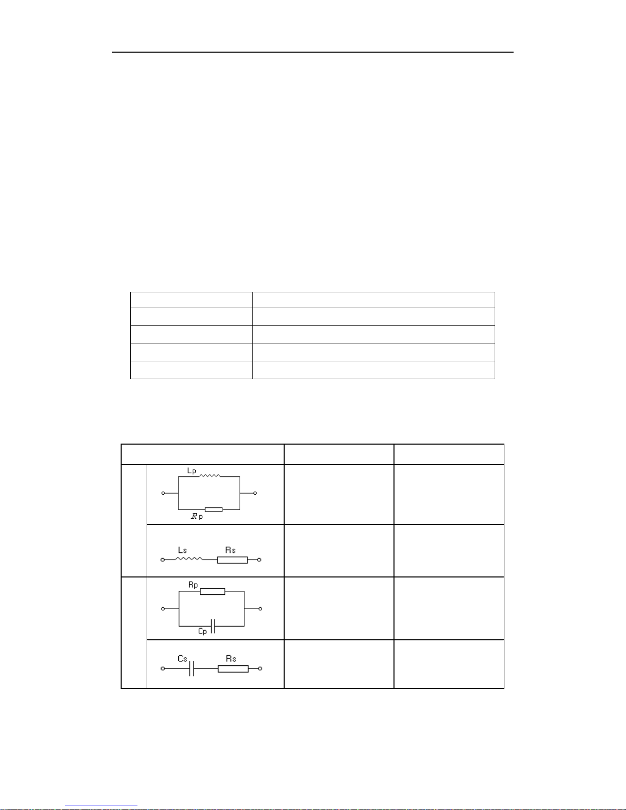
Note: Suffix “s” means series; suff ix “p” means parallel.
2.1.3 Equivalent mode
Series and parallel
Circuit mode Dissipation Conversion
L
D=2πFLp/Rp=1/Q
Ls=Lp/(1+D
2
)
Rs=RpD
2
/(1+D2)
D=Rs/2πFLs=1/Q
Lp=(1+D
2
)Ls
Rp=(1+D
2
)Rs/D2
C
D=1/2πFCpRp=1/Q
Cs=(1+D
2
)Cp
Rs=RpD
2
/(1+D2)
D=2πFCsRs=1/Q
Cp=Cs/(1+D
2
)
Rp=Rs(1+D
2
)/D2
Q=Xs/Rs, D=Rs/Xs, Xs=1/2πFCs=2πFLs
Note: Suffix “s” means series; suffix “p” means parallel.
Page 11

TX7410 Operation Manual
8
The real-world capacitor, resistor and inductor are not ideal, but component of complex
impedance in the form of serial connection or parallel connection. The instrument
calculates necessary values according to equivalent circuit connected in series or parallel.
And different result will be obtained in different circuits, differing in different components.
Two equivalent modes can be conversed through some formulas, and Q and D don’t
change in different modes, as shown in the above figure.
Generally speaking, component with low impedance (such as large capacitor and small
inductor) is usually measured in series mode, and component with high impedance (such
as small capacitor and large inductor) is usually measured in parallel mode. And the
equivalent mode can be decided according to the application of component. If a capacitor
is used for power filtering, series mode is the best choice, and if it’s used fo r LC oscillat
circuit, parallel mode should be selected.
2.1.4 Range
Auto, Manual
9 ranges for LCR measurement
2.1.5 Trigger mode
Internal, External, Manual, Bus
Internal:
When the trigger mode is set to INTernal trigger mode, the instrument
continuously repeats measurements.
External:
When the trigger mode is set to EXTernal, the instrument perform s a single
measurement every time a low-to-high transition TTL level signal is applied to
the Handler interface on the rear panel.
BUS:
When the trigger mode is set to BUS trigger mode, the instrument performs a
single measurement every t ime the *TRG c ommon com mand is sent to TX7410
via GPIB. The BUS trigger mode cannot be set on the front panel. Send the
TRIGger:SOUR ce BUS c omman d via GP IB or RS 232C to s et the t rigger mode t o
the BUS trigger mode.
Manual:
When the trigger mode is set to MANual trigger mode, the instrument performs
a single measurement every time when TRIGGER key on the front panel is
pressed.
2.1.6 Measuremetn delay
Waiting time after measurement completes. If HANDLER interface clear has been set,
signal on HANDLER interface will be cancelled after delay.
Page 12

TX7410 Operation Manual
9
2.1.7 Measurement terminal mode
Common measurement: 4-term inal pair
Hcur: high current (abbreaviation: Hc) Lcur: low current (abbreaviation: Lc)
Hpot: high potential (abbreaviation: Hp) Lpot: low potential (abbreaviation: Lp)
Transformer measurement: 2-terminal
Hpot---Lpot: transformer’s primary (winding A)
Hcur---Lcur: transformer’s secondary (winding B)
Note: Make sure shielding terminals of Hcur and Lcur are reliably short with low impe dance
when the test fixtures or cables used don’t come standard with the instrument.
2.1.8 Measurement speed
Measurement speed can be affected by test frequency , integral time, value of component,
display mode, range mode, average ti mes a nd c omparator. And the following parameters
are evaluated at the status of frequency of 10kHz, range hold, comparator off, no
communication interface, which is possibly maximum values:
FAST: about 20meas/sec
MED: about 10meas/sec
SLOW: about 2meas/sec
At the frequency of being lower than 1kHz, measurement speed will slow down. And
transformer parameter measurement at the same conditions, especially resistance
measurement, will have lower speed.
2.1.9 Filtering depth
1~99, programmable
2.1.10 Basic accuracy
0.1%
2.2 Test Signal
2.2.1 Test singal frequency
10 typical frequencies: 50Hz, 60Hz, 100Hz, 120Hz, 1kHz, 10kHz, 20kHz, 40kHz, 50kHz,
100kHz.
Frequency accuracy: 0.02%
2.2.2 Test signal level
3 test levels: 0.1V, 0.3V, 1V
Page 13

TX7410 Operation Manual
10
Accuracy: ±(10%×set value+2mV)
2.2.3 Output impedance
30Ω±5%, 100±5% (fixed at 100Ω source impedance at bias mode)
2.2.4 Measurement display range
Parameter Display range
L
0.001μH~99.999kH
C
0.001pF~9999.9μF
R, X, Z
0.0001Ω~99.999MΩ
D
0.0001~9.9999
Q
0.0001~9999.9
θ
Angle: -179.99°~179.99°
Radian: -3.1415~3.1415
%
-99.999%~999.99%
If non-percentage data is out of display range, it will be displayed as 99999.
2.3 Function
2.3.1 Correction
Open correction:
to eliminate measurement errors due to parasitic stray admittance (C,
G) of the test fi x tur e.
Short correction:
to eliminate measurement errors d ue t o parasitic residual impedances
(L, R) of the test fi x t ure.
Cable length c ali bratio n:
0m: to measure with terminal fixture;
1m: to measure with 1m cable of TX7000,7001
CUST: to calibrate with cable of required length. And the shipped instrument hasn’t been
performed calibration.
Correction function can be turned off.
2.3.2 Comparator
The instrument can perform multi-bin sorting and support signal output of HANDLER
interface.
BIN1 t o B IN 3 :
Both primary and secondary measurement paramet ers a re wi thin limits.
OU T B I N:
P rimary parameter is not within limits. Or primary parameter is within limits,
secondary parameter is not within limits, and AUX bin is off.
Page 14

TX7410 Operation Manual
11
AUX BIN:
Primary parameter is within limits, but whose secondary parameter
measurement result is not within limits.
Sorting mode:
ABS (absolute deviation):
absolute deviation between measured result and nominal
value is compared with bin limit.
PER (percentage deviation):
percentage deviation between measured result and
nominal value is compared with bin limit.
2.3.3 Parameter display
Direct:
The actual measured values will be displayed.
⊿:
Absolute devation between measured result and nominal value is displayed.
⊿%:
Percentage deviation between measured result and nominal value is displayed.
2.3.4 Automatic LCZ
The instrument automatically selects L, C, Z and e q uivalent mode according to impedance
characteristics of the device under test, to automatically recogonize unkown and mixing
components.
At AUTO mode, primary and secondary parameters are selected according to impedance
angle:
Impedance angle Primary and secondary parameters
θ>5
o
L-Q
θ<-5o C-D
others Z-θ
Equivalent mode is selected according to impedance:
Impedance Equivalent mode
Z>1kΩ parallel
Z<1kΩ series
Keep the original pa ramet er at simila r status of sho rt ci rcuit or o pen circuit. If primary and
secondary parameters are modified, automatic LCZ function will be cancelled.
2.3.5 Discharging test
The instrument is operated with external bias, and generally external bias source has DC
isolated circuit. When discharging function is turned on, the instrument will perform
low-impedance discharge on sampling path to reduce the effect on test accuracy and
speed caused by charge on isolated capacitance. Low impedance lasts for 10 to 20ms.
Page 15

TX7410 Operation Manual
12
2.3.6 Memory
The instrument’s measurement parameter, such as frequency and level, measurement
setups, comparator ’s limit data can be stored in nonvolatile storage in the form of files.
When they’re needed, they can be loaded directly from file menu to save time. And the
latest saved and loaded file will be automatically loaded when the instrument i s turned on
next time.
2.3.7 Interface
IEEE4 88 i nterfa ce:
also called GPIB interface and equal to IEC625 interface, but
having different linker. Communication command is in the format of SCPI and all
commands and data on BUS are sent in ASCII code. The interface supports automatic
FETCH, and has the functions of SH1, AH1, T5, L4 , RL1 , DC1 , D T1 , C0, and E 1. It has
the compatibility of IEEE488.1 and IEEE488.2.
RS232C interface:
It uses standard minimum subclass of RS232C and doesn’t
support hardware connecti on. The interf ace has tra nsfer baud rat e: 4800bps, 9600b ps,
11520bps, 12800bps, 14400bps, 19200bps, 28800bps, and 38400bps, signal logic
level of ±8V and m ax im um t rans fe r d is ta nc e o f 15m . The communication command
is in the format of SCPI, and all commands and data on BUS are sent in ASCII code.
The interface supports automatic FETCH, and ending symbol supports LF, CR, CR+LF.
HANDLER interface:
It receives trigger si gnal and output sorting comparison res ult
signal and outputs synchronous signal of measurement (IDX, EOM). Low level is valid
for logic level. It has internal pull-up resistance and external power is defautly used.
Trigger edge has two options of rising or falling. And measurement output signal is
optional to be cleared after measurement delay.
Page 16
TX7410 Operation Manual
13
Chapter 3 Panel Introductions
3.1 A Tour of Front Panel
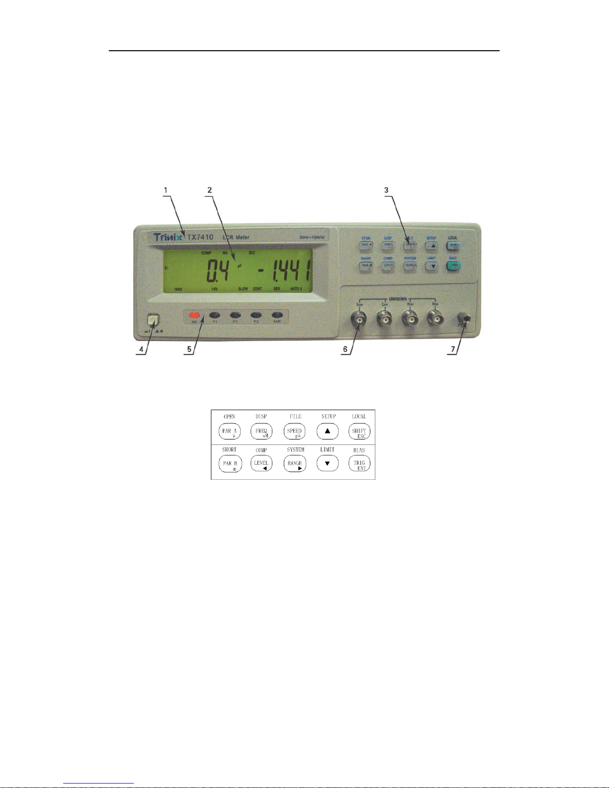
Figure 3-1 Front panel overview
Figure 3-2
Softkeys
1) Brand and Model
The registered brand of our company and model of t he instru ment a re printed .
2) LCD
240×64 dot-matrix Liquid Crystal Display (LCD) displays measurement results, test
conditions, etc.
3) Sorting indicators
It indicates sorting result: NG—not good
P1—pass BIN1
P2—pass BIN2
P3—pass BIN3
AUX—auxiliray bin
Page 17
TX7410 Operation Manual
14
4) Power on/off
Power on/off switch. In the “I” position all oper ating voltages are applied to the instrument .
In the “O” position NO operating voltages are applied to the instrument.
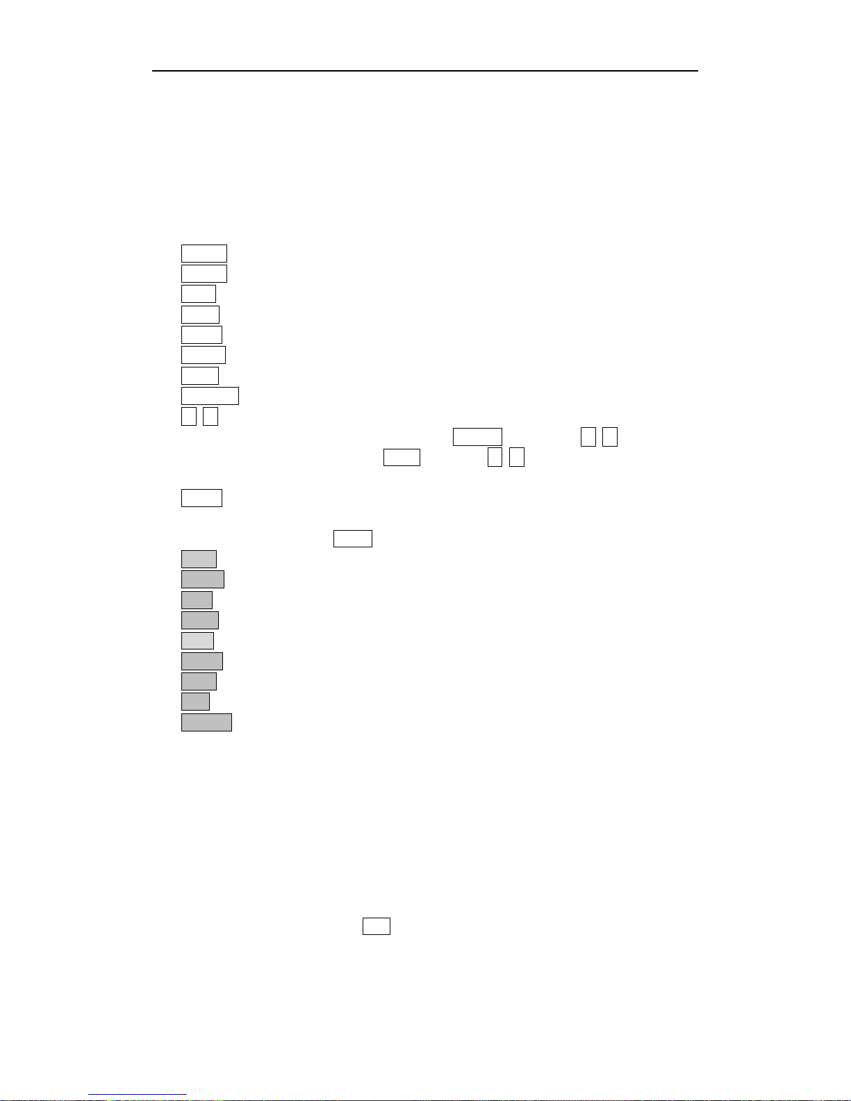
5) Softkeys
They have functions of three levels:
a) Functions by directly pressing softkeys
PARA A: to select primary parameters
PARA B: to select secondary parameters
FREQ: to set frequency
LEVEL: to select level
SPEED: to select measurement speed
RANGE: to set range HOLD/AUTO
SHIFT: to shift to second function
TRIGGER: to trigger single measurement
▲ ▼ is used to select select PAR, PAR B, FREQ, LEVEL, SPEED or RANGE,the object
is determined by the formal press. If pressPARA A firstly, then ▲ ▼ corresponds
with parameter selection;pressFREQ key,then ▲ ▼ corresponds wit h frequen cy
selection.
LOCAL: to enter local operation at remote control mode (RMT status)
b) Functions by pressing SHIFT softkey
OPEN: to perform open correction
SHORT: to perform short correction
DISP: to select parame t er display mode
COMP: to turn on or off comparator
BIAS Bias function turn on or off
SETUP: to enter measurement setup menu
LIMIT: to enter list sweep setup menu
FILE: to enter file management function menu
SYSTEM: to enter system setup menu
c) Only the following menu keys are valid after entering menu:
【ESC】
【ENTER】
【▲】: to select option or add 1
【▼】: to select option or minus 1
【
▲
】: to select option
【
▼
】: to select option
【m】、【 μ 】、【 n】 、【 M】 、【 p】 、【 k】 in limit set menu,when modifying limit data, p ress
unit rate directly to replace ENT key.
Unit rate:【 p】means×10
-12
,【 n】means×10-9,【μ】means×10-6,【 m】means×
10
-3
,【 k】means×103,【 M】means×106.
Page 18
TX7410 Operation Manual
15
6) UNKNOWN terminals !
These are the UNKNOWN Terminals used to connect a four-terminal pair test fixture or test
leads for measuring the device under test.
HD(H
CUR
): High current drive
HS(H
POT
): High potential sense
LS(L
POT
): Low potential sense
LD(L
CUR
): Low current drive
Note: Make sure shielding t erminals of Hcur and Lcur are reliably short with low impedance
when the test fixtures or cables used don’t come standard with the instrument.
7) Frame terminal
!
This is the FRAME Terminal which is tied to the instrument's chassis and whi ch can be use d
for measurements that require guarding.
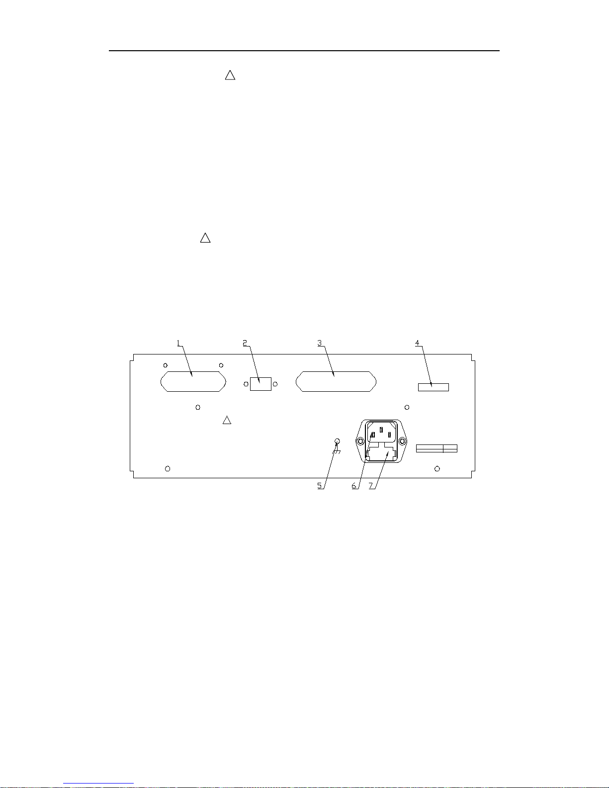
3.2 A Tour of Rear Panel
GPI B
RS-232C
HANDL ER
WARNI NG
!
NO USER SERVICEABLE PARTS CONTAI NED,
DO NOT RE MOVE C OVE RS . HA ZA RD OUS VOL T A GE S P R ES E NT .
REFER SERVI CE TO QUALI FI ED PERSONNEL.
DO NOT CONNEC T A NY DC/ A C CUR RENT / V OLT AGE SOUR CE
TO TEST OR MONITOR TERMI NAL.
~
LI NE V OLT AGE
FUS E
220V/50Hz
250V T1AL
Figure 3-3 Rear panel overview
1) IEEE488 (GPIB) interface connector (Optional)
This is the IEEE488 interface connector used when operating on the General Purpose
Interface Bus.
2) RS232C interface connector
This is the RS232C interface connector used when operating on the serial interface.
3) HANDLER interface connector
This is the HANDLER interface connector used when operation with a component handler
to fully automate component testing, sorting, and quality control data processing.
4) Name plate
Name plate is used to provide the information of date, model, lot number and
Page 19
TX7410 Operation Manual
16
manufacturer etc.
5) Grounding
If the power cord doesn’t ground or isn’t reliably grounding, please connect grounding line!
6)LINE input receptacle
AC power cord receptacle.
7) Fuse holder
Fuse holder for TX7410 line fuse, 220Vac, 1A.
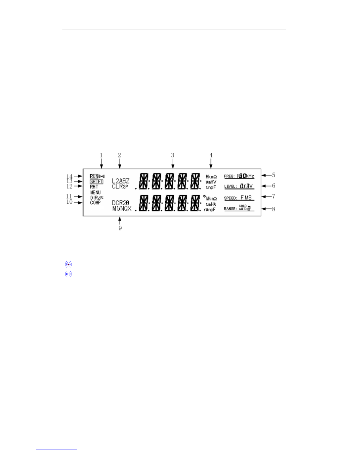
3.3 Display Description
Figure 3-4 Display area
1) Alarm display
“
”on: to turn on alarm
“
” off: to turn off alarm
2) Primary parameter indicator
It indicates primary parameters of the currently measured component.
TX7410 has the following primary parameters: L
S
, LP, CS, CP, RS, RP, Z.
3) Measurement result display
It displayes measurement results of the device under test.
4) Unit display of primary and secondary parameters
It displays units of primary and secondary par ameters.
Inductance unit: μH, mH, H
Capacitance unit: pF, nF, μF
Resistance/impedance unit: mΩ, Ω, kΩ, MΩ
Angle unit:
o
, r
5) Signal frequency indicator
Page 20

TX7410 Operation Manual
17
TX7410 has 10 typical frequenci es from 50Hz to 100kHz.
6) Singal level indicator
“0.1V”: current signal voltage is 0.1V.
“0.3V”: current signal voltage is 0.3V.
“1V”: current signal voltage is 1V.
7) Measurement speed indicator
“F”: fast
“M”: middle
“S”: slow
8) Range indicator
“AUTO”: range auto
“HOLD”: range hold
Digit 0-9 indicate s current range number.
TX7410 has the f unction of measuring DC resistance. DC resistance doesn’t have common
range with AC parameters, so current di splay and operatable range can be switched.
9) Secondar y parameter i ndicator
It indicates secondary parameters of the currently measured component.
TX7410 has the following secondary parameters: θ° (angle), θr (radian), R, X, Q, D.
10) Comparat o r i ndicato r
“COMP” on: Comparator function is turned on.
“COMP” off: Comparator function is turned off.
11) Display mode of primary parameter
It indicates current display mode of primary parameter:
“DIR” on: dire ct mode.
“⊿” on: absolute deviation mode.
“%” on: percentage deviation mode.
12) RMT
RMT means the instrument is at the stat us of remote communication when only LOCAL key
can be operated on panel.
13) Second function ind icator
SHIFT on: second function
SHIFT off: first function
14) Test status indicator
RUN on: The instrument is performing a measurement.
RUN off: The instrument isn’t performing measurement.
Page 21
TX7410 Operation Manual
18
Chapter 4 Operation Instructions
4.1 Turning on the Instrument
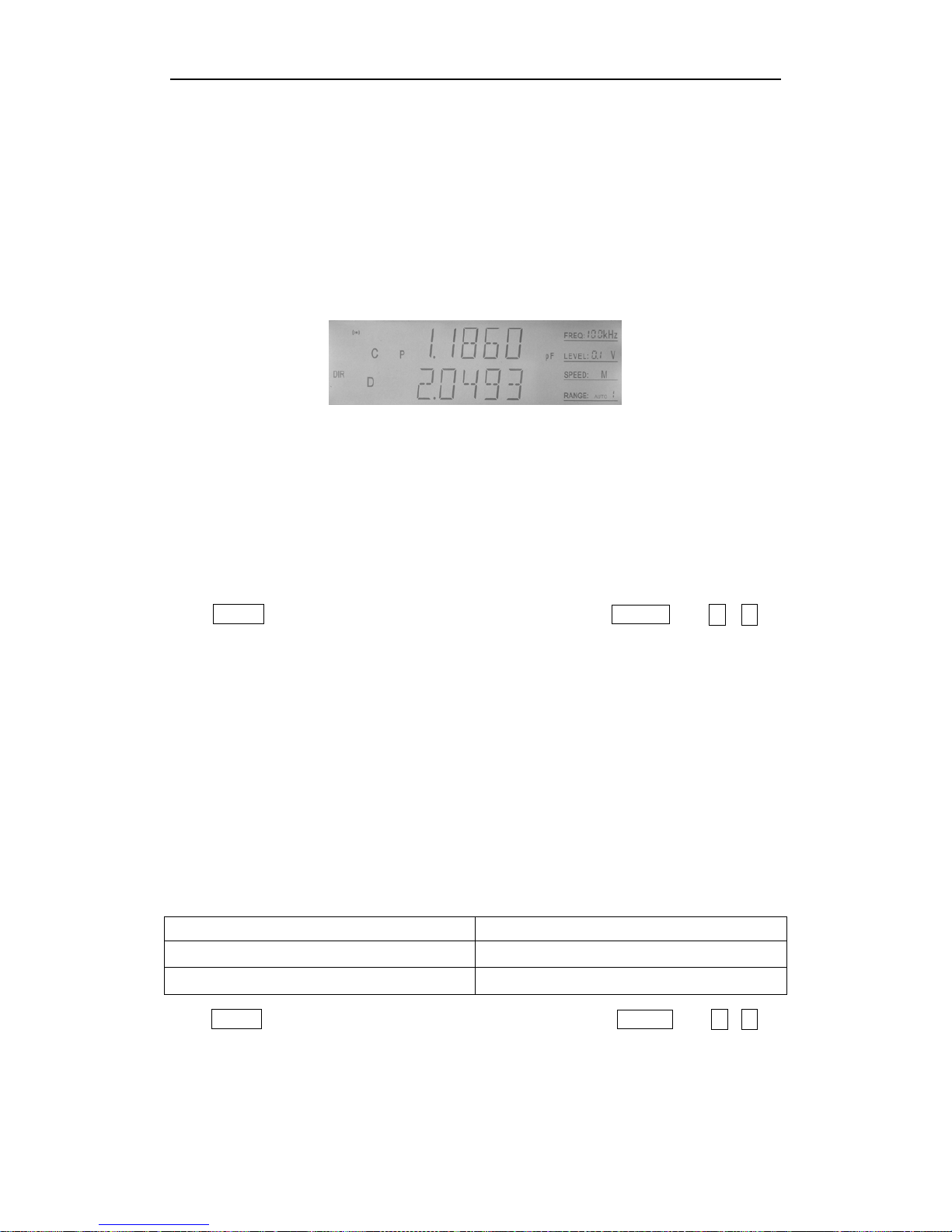
1) Press POWER key to turn on instrument.
2) The instrument enters test status after self-inspection, as shown in Figure 4-1.
Figure 4-1 Test status
4.2 Function Operations
4.2.1 Primray parameter setup
TX7410 has the following primary parameters: LS, LP, CS, CP, RS, RP, Z.
Press PARA A key, and the primary parameter changes. Or pressPARA A, then
▲、▼ to
switch parameter. If the primary parameter changes, secondary parameter also changes:
Ls, Lp —— Q;
Cs, Cp —— D;
Rs, Rp —— X;
Z —— θr (radian);
4.2.2 Secondary parameter setup
TX7410 has the follo wing common secondary parameters: θ° (angle), θr (radian), R, X, Q,
D.
TX7410 also has the function of measuring DC resistance and transformer parametersw.
Secondary parameters differ with parimary parameters:
Primary parameters Secondary parameters
CS, CP, RS, RP, Z θ° (angle), θr (radian), R, X, Q, D
LS, LP θ° (angle), θr (radian), R, X, Q, D, DCR
Press PARA B key, and the secondary parameter changes. Or pressPARA B, then▲ 、▼ to
switch parameter.
Page 22

TX7410 Operation Manual
19
4.2.3 Frequency setup
TX7410 has the following test frequencies: 50Hz, 60Hz, 100Hz, 120Hz, 1kHz, 10kHz,
20kHz, 40kHz, 50kHz, 100kHz.
Press FREQ key, and the frequency changes among the foregoing frequencies. Or
pressPREQ, then▲、▼ to switch parameter.
And the current frequency is displayed in frequency area on LCD.
4.2.4 Signal voltage
TX7410 has the following 3 common signal voltages: 0.1V, 0.3V, 1V
Press LEVEL key, and the level changes. Or pressLEVEL, then
▲、▼ to switch level.
And the current voltage is displayed in voltage area on LCD.
4.2.5 Measurement speed
TX7410 has 3 measurement speeds available: F (fast), M (mi ddle), S (slow).
Fast: about 20measurements/second.
Middle: about 10measurement/second.
Slow: about 2measurements/second.
Press SPEED key, and the speed changes. Or pre ssSPEED, then
▲、▼ to switch speed.
And the current measurement spee d is display ed in speeda a rea on LC D in the for m of F, M
or S.
4.2.6 Trigger
When the trigger mode is set manual, the instrument performs one measurement by
pressing TRIGGER key once.
4.2.7 Range setup
TX7410 totally has 9 r anges : 10Ω, 30Ω, 100Ω, 300Ω, 1kΩ, 3kΩ, 10kΩ, 30kΩ, 100k. Please
select range accoding to the impedance of the device under test.
Please refer to the following table for range and its corresponding m easurement rang e.
When the instrument is working at automatic r ange, it can lo ok for the most suitable range
to take measurement, therefore, it’s recommended to select range auto mode mostly, to
avoid incorrect measurement caused by wrong selection of range.
But in some special cases, r ange should be held, such as measurement o f the same t ype in
batch and sorting test, in order to improv e efficiency , speed an d stability. Inductance’s bias
test should be performed at held range.
The way to hold range is to make instrument automatically measure, and hold range after
Page 23
TX7410 Operation Manual
20
measuring out correct and stable v alue , or select ran ge a ccor ding to the im pedance of t he
device under test, referring to the next table.
LCR range:
Range No. Range Measurement range
8 10Ω
0~10Ω
7 30Ω
10Ω~70Ω
6 100Ω
70Ω~300Ω
5 300Ω
300Ω~1kΩ
4 1kΩ
1kΩ~3kΩ
3 3kΩ
3kΩ~10kΩ
2 10kΩ
10kΩ~30kΩ
1 30kΩ
30kΩ~100kΩ
0 100kΩ
100kΩ~∞
Press RANGE key, and the range changes between AUTO and HOLD. Press UP or DOWN
key to manually select range. And the current range No. is displa yed in r ange area on LCD.
4.2.8 Open correction
Press SHIFT + OPEN to enter open correction menu.
TX7410’s open correction function can eliminate the effect of test cable, test fixture and
stray admittance in parallel with the device under test, such as stray capacitance.
Perform the following steps to perform open correction:
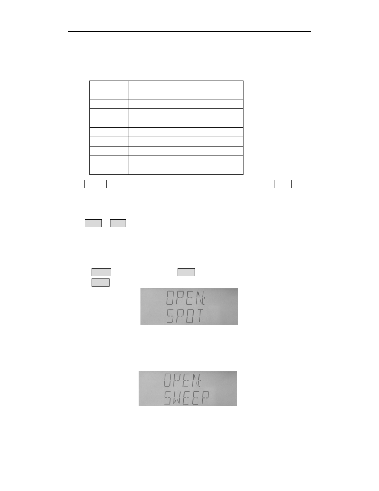
1. Press SHIFT key at test status, and “SHIFT” at left corner is on.
2. Press OPEN key to select correction function, as Figure 4-2 shows on LCD.
Figure 4-2 Open spot correction
3. Select to perform spot or sweep correction through【▲】or【▼】 key, as shown in
Figure4-3.
Figure 4-3 Open sweep correction
“SPOT” means only open correction for the current frequency point; while“SWEEP” means
Page 24

TX7410 Operation Manual
21
open correction for all frequency points.
Note:Press【
▲】【▼
】 to enter short correction menu.
4. Press ESC key to cancel correction and exit to test status.
5. Press ENTER key to start correction.
4.2.9 Short correction
Press SHIFT + SHORT to enter short correction menu.
TX7410’s open correction can eliminate the effect of test cable, test fixture and stray
impedance in series with the devi ce under t est, su ch as le ad resistan ce o r lead inductance.
Perform the following steps to perform short correction:
1. Press SHIFT key at test status, and “SHIFT” at lef t corner is on.
2. Press SHORT key to select cor rection function, as Figure 4-4 shows on LCD.
Figure 4-4 Short spot correction
3. Select to pe rform spot, sweep or DC R correction through【▲】or【▼】 key, as shown
in “SPOT” means only short correction for the current frequency point; while“SWEEP”
means short correction for all frequency points.
Note:Press【
▲】【▼
】 to enter open correction menu.
4. Press ESC key to cancel correction and exit to test status.
5. Press ENTER key to start correction.
4.2.10 Display mode
Press SHIFT + DISP to change display mode.
The instrument has three display modes:
Direct display (DIR)
--- Actual measured value is displayed;
Absolute deviation display (⊿)
– Absolute deviation between measured value and
nominal value is displayed;
Percent age deviation display (%)
– Percentage deviation between measured value
and nominal value is displayed.
Display mode only works for primary parameter, not secondary parameter.
Shift of display mode is related to tolerance mode of primary parameters:
When tolerance mode is absolute value (ABS ) → Display m ode shifts be tween DIR and
⊿
When tolerance mod e is perc entage (PER) → Display mode shifts between DIR and %.
Page 25
TX7410 Operation Manual
22
For exampl e:
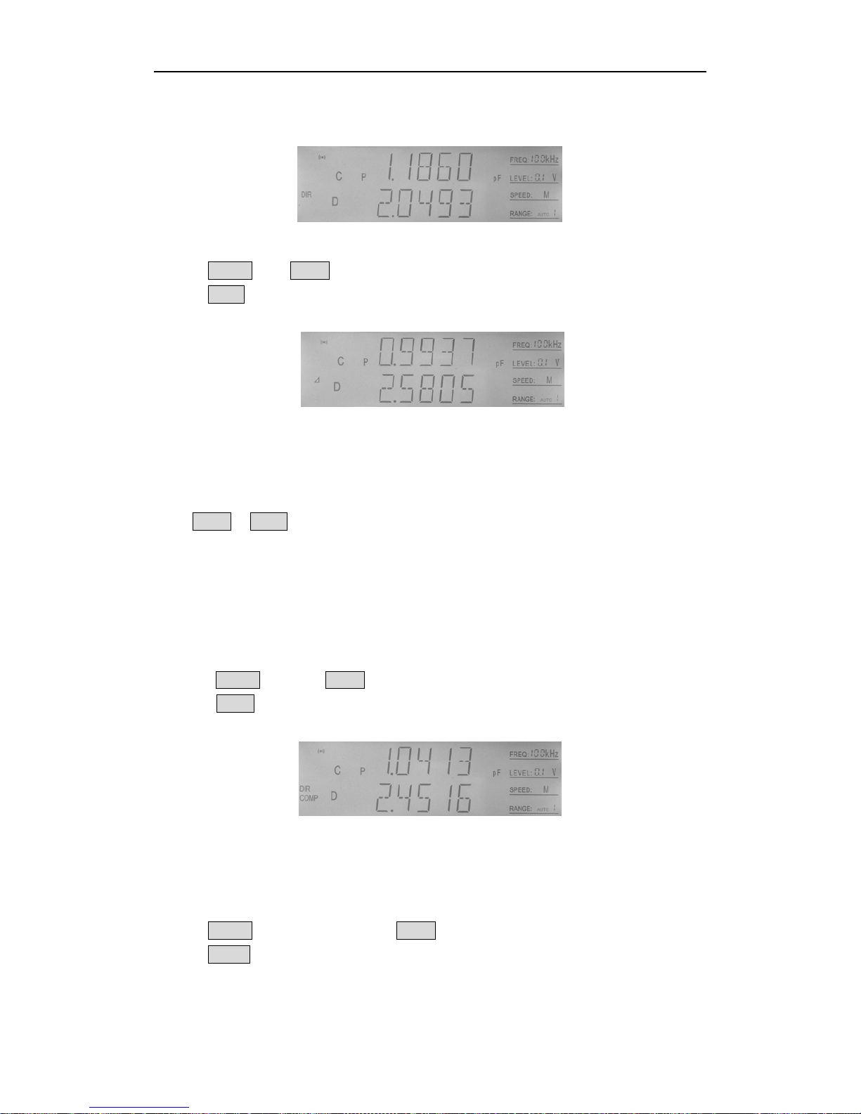
1. The current display mo de is DIR, and “ DIR ” is displa ye d on L CD , as sh own i n Figu re4-5.
Figure 4-5 Direct display mode
2. Press SHIFT key, “SHIFT” at left corner is on.
3. Press DISP key, “⊿” or “%” is displayed on LCD, as shown in Figure 4-6.
Figure 4-6 Absolute deviation display mode
Note: Please refer to limit list setup for tolerance mode.
4.2.11 Comparator
Press SHIFT + COMP to turn on or off comparator.
After comparator is turned off, comparator indicator on panel is off, alarm doesn’t beep,
comparison result doesn’t output through HANDLER interface, EOM of measurement’s
ending signal doesn’t output, but AD shift signal IDX and trigger input TRIG are still valid.
After comparator is turned on, “COMP” is displayed on LCD.
Perform the following steps to turn on or off comparator function:
1. Press SHIFT key, and “SHIFT” at left corner is on.
2. Press COMP key, “COMP” is displayed on LCD, which means comparison function has
been turned on, as shown in Figure 4-7.
Figure 4-7 Comparison function on/off
4.2.12 Measurement setup
Perform the following steps to enter measurement setup page:
1. Press SHIFT key at test page, and “SHIFT” at left corner is on.
2. Press SETUP key to enter measurement setup page, as shown in Figur e 4-8.
Page 26

TX7410 Operation Manual
23
Figure 4-8 Me a su re ment setup page
Measurement setup includes the following items
TRIG: trigger mode;
DELAY: measurem en t delay;
FILT: filtering depth;
SRES: source resistance;
DCHR: discharging test;
CABLE: cable length;
ALCZ: auto LCZ switch;
ZERO: correction switch
At measurement setup page, press 【
▲
】or 【▼】 key to select item, press【▲】or 【▼】
key to modify value, then press【 ESC】 to exit form measurement setup or data
modification. When data input is vali d, press 【ENTER】 key to enter data modification, and
when data input isn’t valid, press【ENTER】to exit, as【ESC】 key works.
1) TRIG
The instrument starts one measurement only after receiving one trigger signal.
There are four trigger modes: INT (internal, EXT (external), MAN (manual), BUS. The
instrument only receives trigger signal at current trigger mode.
Internal:
When the trigger mode is set to INTernal trigger mode, the instrument
continuously repeats measurements.
External:
When the trigger mode is set to EXTernal, the instrument performs a single
measurement every time a low-to-high transition TTL level signal is applied to
the Handler interface on the rear panel.
BUS:
When the trigger mode is set to BUS trigger mode, the instrument performs a
single measurement every t ime the *TRG c ommon com mand is sent to TX7410
via GPIB. The BUS trigger mode cannot be set on the front panel. Send the
TRIGger:SOUR ce BUS c omman d via GP IB or RS 232C to s et the t rigger mode t o
the BUS trigger mode.
Manual:
When the trigger mode is set to MANual tri gger mode, the inst rument perform s
a single measurement every time when TRIGGER key on the front panel is
pressed.
Perform the following steps to change trigger mode:
a) Select “TRIG ” through 【▲】or【▼】key, as shown in Figure4-9.
Page 27
TX7410 Operation Manual
24
b) Press 【▲】or【▼】 to select “INT”, “MAN”, or “EXT”.
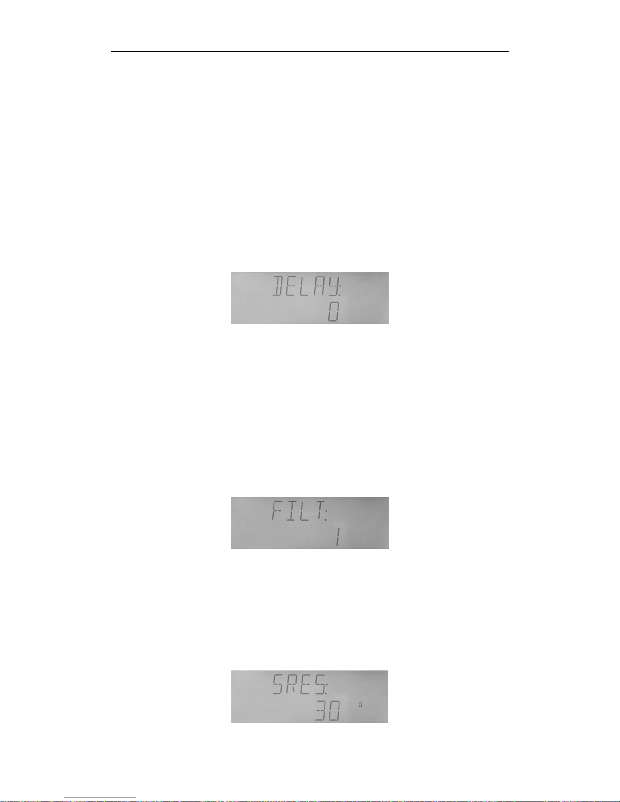
2) DELAY
Programmable delay from the trigger command to the start of the measurement, 0 to
60.000 s in 1 ms steps.
Perform the following steps to set delay time (unit: ms)
a) Select “DELAY” through 【
▲
】or【▼】key, as shown in F igure4-9.
b) Press 【▲】or【▼】 to add or minus delay time.
b) Press 【ENTER】key to enter data modification, and the data which is going to be
modified twinkles, press 【▲】or【▼】key to change value. Then press 【ENTER】
key to ensure data input, and 【ESC】key to cancel.
c) Press 【ESC】key to exit.
Figure 4-9 Delay setup
3) FILT
Perform the following steps to set filtering depth:
a) Select “FILT” through 【
▲
】or【▼】key, as shown in Figure4-10.
b) Press 【▲】or【▼】 to add or minus filtering depth.
c) Press【ENTER】key to enter data modification, and the data which is going to be
modified twinkles, press 【▲】or【▼】key to change value. Then press 【ENTER】
key to ensure data input, and 【ESC】key to cancel.
d) Press 【ESC】key to exit.
Figure 4-10 Filtering depth se tu p
4) SRES
Perform the following steps to set source resistance:
a) Select “SERS” through 【
▲
】or【▼】key, as shown in Figure4-11.
b) Press 【▲】or【▼】key to select “100Ω” or “30Ω”.
c) Press 【ENTER】key or 【ESC】key to exi t.
Page 28
TX7410 Operation Manual
25
Figure 4-11 Resistance selection
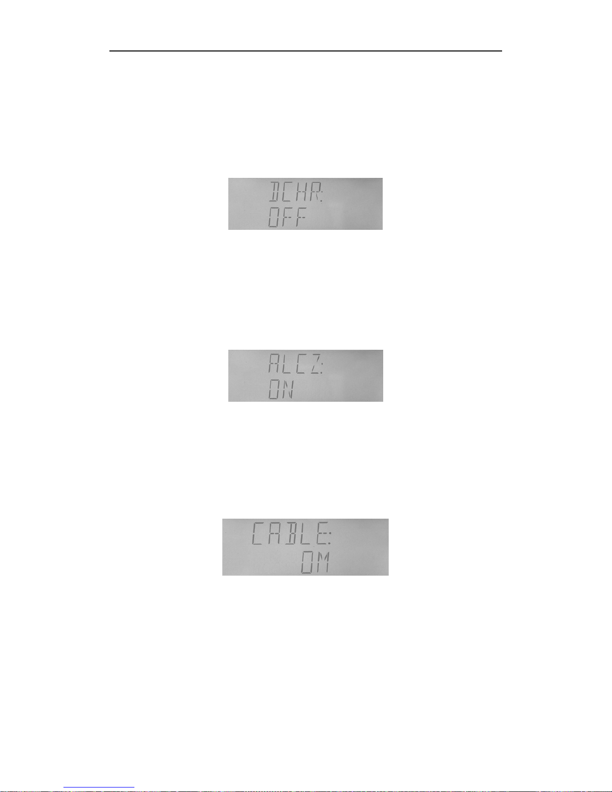
5) DCHR
Perform the following steps to turn on or off discharging test:
a) Select “DCH R” through 【
▲
】or【▼】key, as shown in Figure4-12.
b) Press 【▲】or【▼】key to select “ON” or “OFF”.
c) Press 【ENTER】key or 【ESC】key to exi t.
Figure 4-12 Discharging switch
6) ALCZ
Perform the following steps to turn on or off auto LCZ:
a) Select “ALCZ” through 【
▲
】or【▼】key, as s hown in Figure4-13.
b) Press 【▲】or【▼】key to select “ON” or “OFF”.
c) Press 【ENTER】key or 【ESC】key to exi t.
Figure 4-13 Automatic LCR switch
10) CABLE
Perform the following steps to set cable length:
a) Select “CABLE” through 【
▲
】or【▼】key, as shown in F igure4-14.
b) Press 【▲】or【▼】key to select “om”, “1m” or “CUST”.
c) Press 【ENTER】key or 【ESC】key to ex i t .
Figure 4-14 Cable length set u p
11) ZERO
Perform the following steps to turn on or off correction function:
a) Select “CABLE” through 【
▲
】or【▼】key, as shown in F igure4-15.
b) Press 【▲】or【▼】key to select “ON” or “OFF”.
c) Press 【ENTER】key or 【ESC】key to ex i t .
Page 29

TX7410 Operation Manual
26
Figure 4-15 Correction switch
4.2.13 Limit list setup
TX7410 can set 3-bin limit data of primary parameter, and 1-bin limit data of secondary
parameter.
The comparison result can be indicated through sorting indicators:
OUT: fail;
P1: pass bin 1;
P2: pass bin 2;
P3: pass bin 3;
AUX: auxiliary bin
The result can be output from HANDLER interface:
/BIN1/BIN2/BIN3: pass bins;
/AUX: auxiliary bin;
/OUT: fail bin;
/PHI: higher primary parameter;
/PLO: lower primary parameter;
/SREJ: secondary parameter fails
The result can also be output from alarm, referring to system setup.
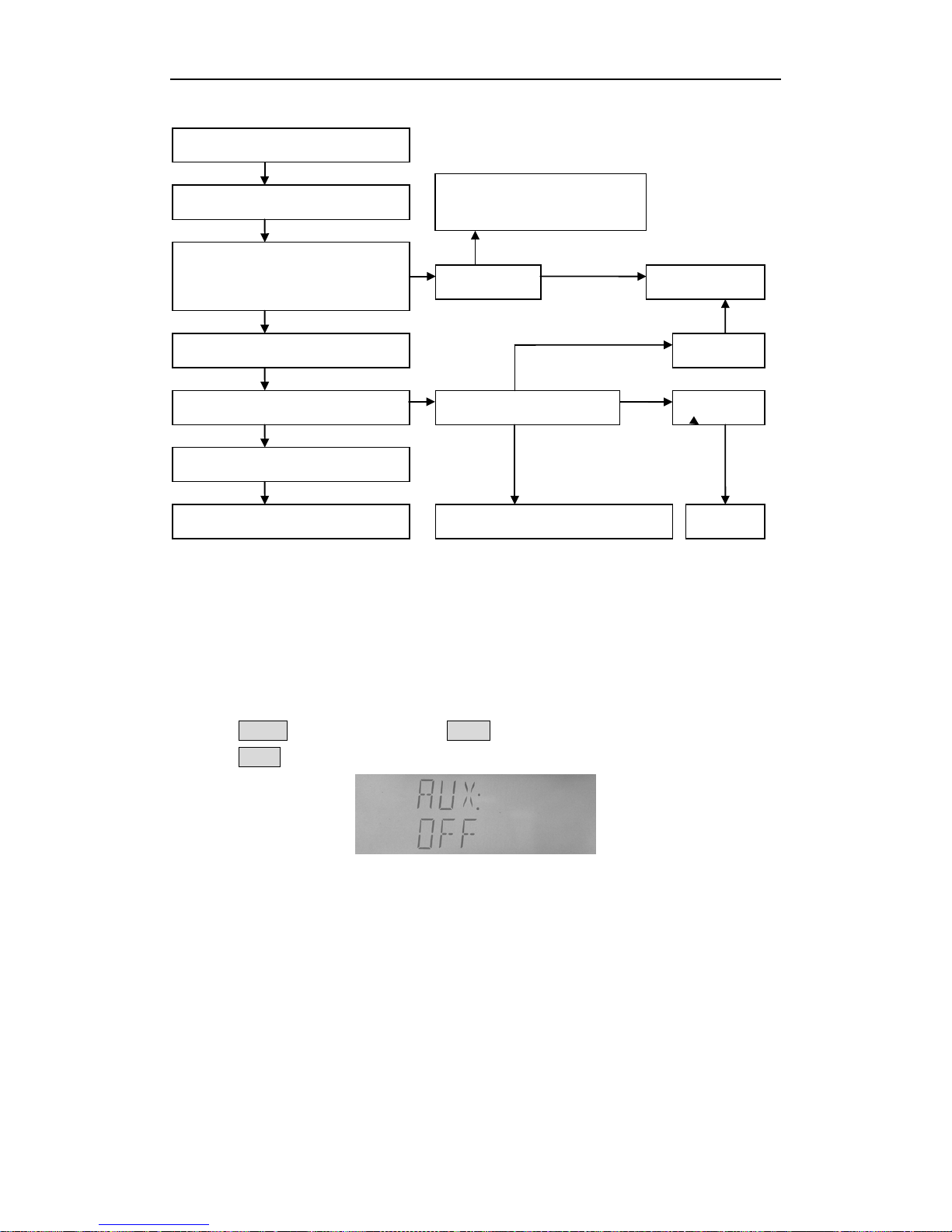
Comparator’s comparison and sorting:
Page 30
TX7410 Operation Manual
27
Figure 4-16 Comparator’s comparison an d sorti ng
Please first set limit list before using comparat or fun ction. If data in limit table aren’t set, it
will be 0.
Perform the following steps to enter limit list setup page:
1. Press SHIFT key at test page, and “SHIFT” at left corner is on.
2. Press LIMIT key to enter setup page, as shown in 4-17.
Figure 4-17 Limit list setup page
The following comparator parameters can be set:
AUX: auxiliary bin on/off;
MODE: tolerance mode of primary parameter;
NOM: nominal value of primary parameter;
BIN1L: low lim it of primary paramete r 1;
BIN1H: high limit of primary parameter 1;
BIN2L: low lim it of primary paramete r 2;
BIN2H: high limit of primary parameter 2;
Measurement completes
Primary parameter comparison
BIN 1 comparison first;
If fails, BIN 2 comparison;
If fails, BIN 3 comparison
Primary parameter passes some bin
Secondary parameter comparison
Secondary parameter passes
PASS BIN (BIN n)
No pass bins FAIL BIN (OUT)
Higher primary parameter (PHI)
Lower primary parameter (PLO)
Secondary parameter fails AUX BIN on
AUX BIN off
Secondary parameter passes (SREJ) AUX BIN
Page 31

TX7410 Operation Manual
28
BIN3L: low limit of primary param e ter 3;
BIN3H: high limit of primary parameter 3;
SEC L: low limit of secondary parameter;
SEC H: high limit of secondary parameter;
At limit setup page, press 【
▲
】or 【▼】 key to select item, press 【▲】or 【▼】 key
to modify value. When data input is valid, press 【ENTER】 key to enter data modification,
and when data input isn’t valid, press【ENTER】to exit, as【ESC】 key wo r ks.
1) AUX
Perform the following steps to turn on or off auxiliary item.
a) Select “AUX” item through【
▲
】or【▼】key at limit setup page, as shown in
Figure4-21.
b) Press【▲】or【▼】key to select “ON” or “OFF”.
c) Press 【ENTER】or【ESC】key to exit.
2) MODE
Primary p aram ete r’s high and low limits can be set in the form of absolute tolerance and
percentage tolerance.
Figure 4—18 Primary parameter’s tolerance mode
Perform the following steps to modify primary parameter’s tolerance mode:
a) Select “MODE” item through【
▲
】or【▼】key at limit setup page, as shown in
Figure4-18.
b) Press【▲】or【▼】key to select “ABS” or “PER”.
c) Press 【ENTER】or【ESC】key to exit.
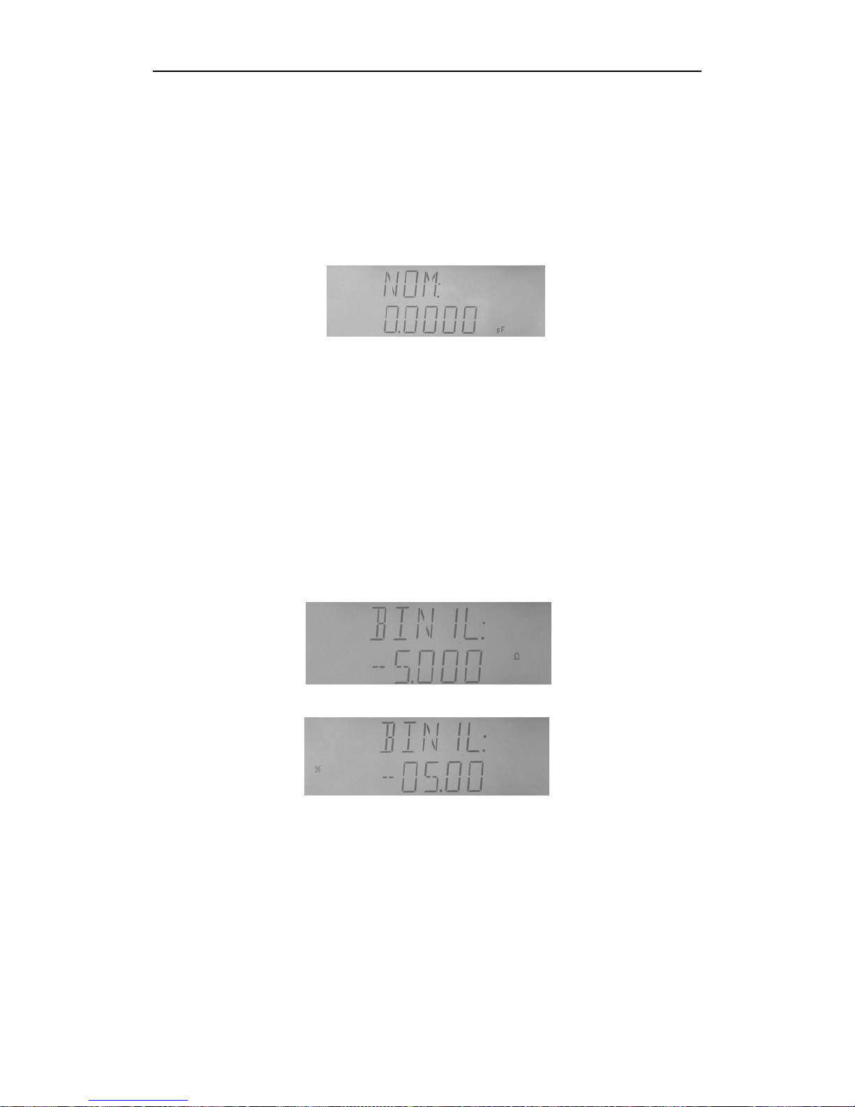
3) NOM
Perform the following steps to set nominal value:
a) Select “MODE” item through【
▲
】or【▼】key at limit setup p age, as shown in
Figure4-19. The current nominal value is displayed at the second line with unit
corresponding with current primary parameter’s type and multiple at unit column.
b) Press 【ENTER】key to enter data mo dification status, and the data which is going to
be modified twinkles.
c) Press 【
▲
】or【▼】key to select data that needs modifying.
d) Press 【▲】or【▼】to modi fy v alue to 0,1, 2,3,4 ,5,6, 7 ,8,9 , and the first va lue c ould be
selected to be “-”.
e) If decimal point needs repositioning, p ress 【
▲
】or【▼】key to select the decimal
Page 32
TX7410 Operation Manual
29
point to twinkle, then press【▲】or【▼】key to move it.
f) If multiple needs modifying, press 【
▲
】or【▼】key to select the unit and multiple
to twinkle, then press【▲】or【▼】key to modify multiple.
g) After setting, press 【ENTER】key to ensure the modification, or【ESC】key to cancel
it. Or press
【m】、【 μ 】、【 n】、【 M】、【 p】、【 k】 directly, select rate and confi r m data
modification.
h) At the status of non-data modification, press【ESC】key to exit.
Figure 4-19 No mi n al value setup
4) High and low limits of primary parameters setup (BIN 1L,BIN1H,BIN2L,BIN2H,
BIN3L,BIN3H)
At limit setup page, select item of BIN1L, BIN1H, BIN2L, BIN2H, BIN3L, BIN3H through
【
▲
】or【▼】key, to set limits of bins.
At absolute tolerance mode, high and low limits of primary parameters are displayed in the
similar way of nominal value with unit and multiple; at percentage tolerance mode,
corresponding data are displayed in the form of percentage without unit and multiple. For
example, at percentage tolerance mode, low limit of BIN1 is -5.000, then it will be
displayed as -5%, as shown in Figure 4-20 and 4-21.
Figure 4-20 Data display at absolute tolerance mode
Figure 4-21 Data display at percentage tolerance
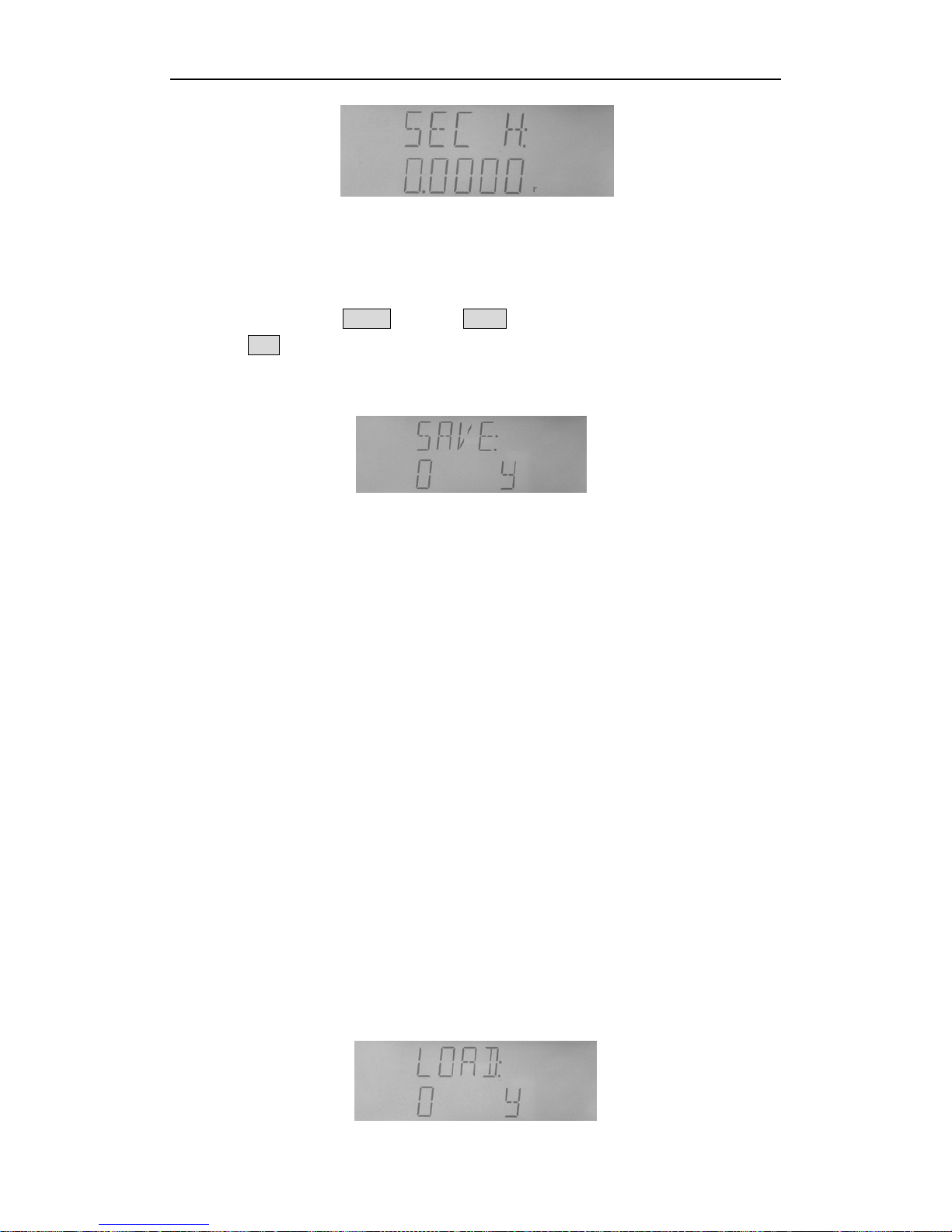
5) High and low limits of primary parameters setup (SEC L, SEC H)
There is no nominal v alue f or sec ondary par ameter, so only absolute li mit of n on-deviation
type can be set.
At limit setup page, select SEC L or SEC H through【
▲
】or【▼】key, then set low limit
and high limit of secondary parameter, as shown in Figure 4-22.
Page 33
TX7410 Operation Manual
30
Figure 4-22 Limit setup of secondary parameter
4.2.15 File operation function
Perform the following steps to enter file operation page:
1. At test status, press SHIFT key, and “SHIFT” at left corner is on.
2. Press FILE key to enter file operation page, and the instrument first displays
currently-used file No., (if no file is loaded, the defa u lt set up of file No. 0 displays), as
shown in 4-23.
Figure 4-23 File operation page
File can be saved, loaded or erased.
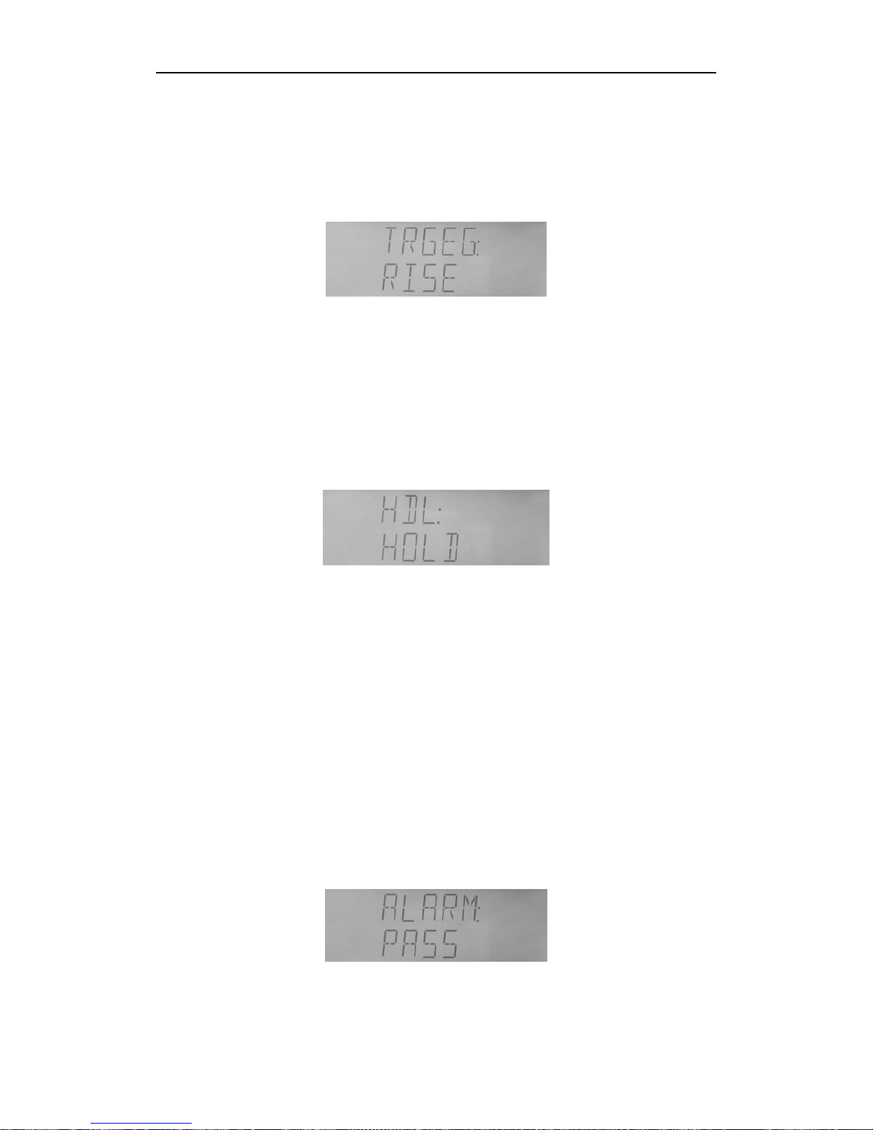
1) SAVE
This operation sav es the current setups to appointed file No. Perfo rm the following st eps to
save file:
a) Select “SAVE” at file oper ation page t hrough【
▲
】or【▼】key , as shown in Figure4-25.
b) Press【▲】or【▼】key to select appointe d file No. from 0-9. Displayed “Y” means the
file has existed, and it will be cove red at t he time of s aving, a nd “N” means the file doesn’t
exist.
c) Press【ENTER】key to perform the savi ng operation, and “WAIT” displays.
d) Press【ESC】to exit.
2) LOAD
The operation loads setups of appointed file. Perform the following steps to load file.
a) Select “LOAD” at file oper ation page th rough【
▲
】or【▼】key, as shown in Figure4-24.
b) Press【▲】or【▼】key to select loading file No. Displayed “Y” means the file has existed,
and it will be loaded, and “N” means the file doesn’t exi st.
c) Press【ENTER】key to perform the loading oper ation, and it automatically exits back to
measurement page after loading completes.
d) Press【ESC】to exit.
Page 34

TX7410 Operation Manual
31
Figure 4-24 Loading file
3) ERASE
Perform the following steps to erase file:
a) Select “ERASE” at file operation page through【
▲
】or【▼】key, as shown in
Figure4-25.
b) Press【▲】or【▼】key to select erasing file No. Display ed “Y” means the file has existed,
and “N” means the file doesn’t exist.
c) Press【ENTER】key to perform the erasing operation, and hint “SURE” to ensure the
operation, press【ENTER】key to erase the file, otherwise, press【ERC】key to give up the
operation.
d) Press【ESC】to exit.
Figure 4-25 Erasing file
4.2.16 System function setup
System setup includes the following items:
BUS: BUS mode
ADDR: GPIB address;
BAUD: RS232C communication baud rate;
DELIM: ending symbol;
FETCH: fetch mode;
TRGEG: HANDLER interface’s trigger edg e ;
HD: HANLDER interface’s signal hold;
ALARM: comparator alarm;
SOUND: alarm sound;
KBEEP: key beep on/off;
KLOCK: key lock on/off;
SAVE: saving system setups
Perform the following steps to enter system setup page:
1. At test status, press SHIFT key, and “SHIFT” at left corner is on.
2. Press SYSTEM key to enter system setup page, as shown in 4-26.
Page 35

TX7410 Operation Manual
32
Figure 4-26 System setup
1) BUS
There are 3 BUS types:
OFF:
communication interface off;
RS232:
RS232C communication interface is turned on, a nd GPIB com munication f unct ion
is turned off;
GPIB:
GPIB (IEEE488) communication interface is turned on, and RS232C
communication function is turned off.
Perform the following steps to select BUS type:
a) At system setup page, select “BUS” through 【
▲
】or【▼】key , as shown in Figure
4-30.
b) Press 【▲】or【▼】key to select “RS232C”, “GPIB” or “OFF”.
c) Press 【ENTER】key or【ESC】key to exit.
2) ADDR
Address can be changed from 0 to 31.
Perform the following steps to select:
a) At system setup page, select “ADDR” through 【
▲
】or【▼】key , as shown in Figure
4-17.
b) Press 【▲】or【▼】key to add or minus addres s.
c) Press 【ENTER】key to enter data modification status and modifying data twinkles,
then press【
▲
】or【▼】key to select the data that is going t o be m odified, press【▲】
or【▼】key to modify value. Then press【ENTER】key to ensure the modification, or【ESC】
key to give up it.
d) Press 【ESC】key to exit.
Figure 4-27 Communication address setup
3) BAUD
TX7410’s RS232C supports 8 common baud rates: 4800bps, 9600bps, 11520bps,
12800bps, 14400bps, 19200bps, 28800bps, and 38400bps.
Perform the following steps to select baud rate:
a) At system setup page, select “BAUD” through 【
▲
】or【▼】key , as shown in Figure
4-28.
b) Press 【▲】or【▼】key to select baud rate.
c) Press 【ENTER】key or【ESC】key to exit.
Page 36

TX7410 Operation Manual
33
Figure 4-28 B au d rate setup
4) DELIM
TX7410 supports to send several common ending symbols:
LF:
line change symbol (ASCII ode 100);
CR:
e nter symbol (ASCII code 13);
CR+LF:
enter to change line
Perform the following steps to select:
a) At system setup page, select “DELIM” through 【
▲
】or【▼】key , as shown in Figure
4-29.
b) Press 【▲】or【▼】key to select ending symbol that needs setting.
c) Press 【ENTER】key or【ESC】key to exit.
Figure 4-29 En ding symbol selection
5) FETCH
The measurement result can be automatically sent or queried when the instrument
communicates with PC through RS232C or GPIB.
Perform the following steps to select:
a) At system setup page, select “FETCH” through 【
▲
】or【▼】key, as shown in Figure
4-30.
b) Press 【▲】or【▼】key to select fetch mode.
c) Press 【ENTER】key or【ESC】key to exit.
Figure 4-30 F etch mode
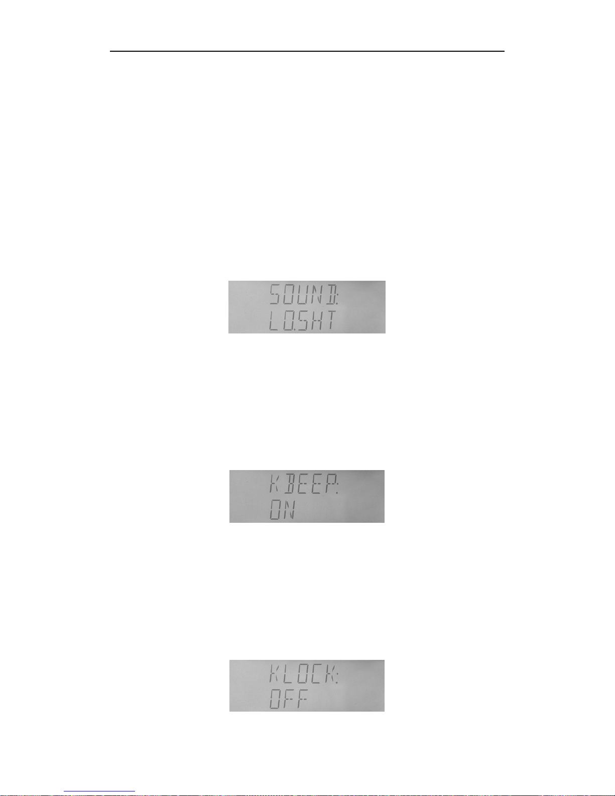
6) TRGEG
There are two kinds of trigger edges:
RISE:
Measurement starts at trigger pulse’s rising edge;
FALL:
Measurement starts at trigger pulse’s falling edge.
Page 37
TX7410 Operation Manual
34
Perform the following steps to set the edge mode:
a) At system setup page, select “TRIGER” through 【
▲
】or【▼】key , as shown in Figure
4-31.
b) Press 【▲】or【▼】key to select trigger edge mode.
c) Press 【ENTER】key or【ESC】key to exit.
Figure 4-31 Trigger edge
7) HDL
Perform the following steps set signal hold:
a) At system setup page, select “HDL” through 【
▲
】or【▼】key , as shown in Figure
4-32.
b) Press 【▲】or【▼】key to select HOLD or CLEAR.
c) Press 【ENTER】key or【ESC】key to exit.
Figure 4-32 HANDLER interface’s signal hold
8) ALARM
TX7410 provides alarm function for sorting result.
OFF:
alarm off;
NOGO:
alarm at fail (no good);
AUX:
alarm at auxiliary bin;
PASS:
alarm at any pass bin
Perform the following steps to set alarm:
a) At system setup page, select “ALARM” through 【
▲
】or【▼】key, as shown in Figure
4-33.
b) Press 【▲】or【▼】key to select alarm mode.
c) Press 【ENTER】key or【ESC】key to exit.
Figure 4-33 Comparator’s alarm setup
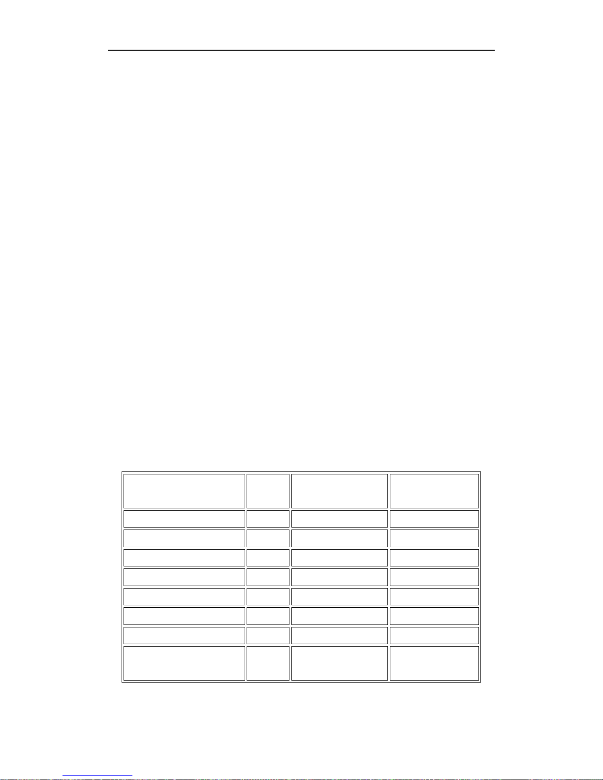
9) SOUND
Page 38
TX7410 Operation Manual
35
There are 6 sounds available:
LO.SHT:
low and short;
LO.LON:
low and long;
LO.TWO:
two short and low;
HI.SHT:
h i gh and short;
HI.LON:
high and long;
HI.TWO:
two short and high
Perform the following steps to set sound:
a) At system setup page, select “SOUND” through 【
▲
】or【▼】key , as shown in Figure
4-34.
b) Press 【▲】or【▼】key to select sound.
c) Press 【ENTER】key or【ESC】key to exit.
Figure 4-34 Comparator’s alarm sound
10) KBEEP
Perform the following steps to set key beep.
a) At system setup page, select “KBEEP” through 【
▲
】or【▼】key, as shown in Figure
4-35.
b) Press 【▲】or【▼】key to turn on or off keylock.
c) Press 【ENTER】key or【ESC】key to exit.
Figure 4-35 Key beep on/off setup
11) KLOCK
Perform the following steps to set keylock.
a) At system setup page, select “KLOCK” through 【
▲
】or【▼】key, as shown in Figure
4-36.
b) Press 【▲】or【▼】key to turn on or off keylock.
c) Press 【ENTER】key or【ESC】key to exit.
Page 39

TX7410 Operation Manual
36
Figure 4-36 Keylock on/off setup
After keylock is set, function keys on panel can’t be available. Press SHIFT, then SYSTEM
to enter “KLOCK” operation, press 【▲】or【▼】to unlock.
12) SAVE
Perform the following steps to save setups:
a) Select “SAVE” through 【
▲
】or【▼】key, as shown in Figure 4-37.
b) Press 【ENTER】to save setups.
Figure 4-37 Saving system setup
Page 40
TX7410 Operation Manual
37
Chapter 5 Remote Control
TX7410 has the RS232C serial interface and the parallel GPIB (optional) interface. Both
interfaces can be used to re mot ely cont rol TX7410 , but they c an not be used at the same
time. The two interfaces share the same program commands, but they have different
hardware configurations and different communicatio n protocols. This chapter provides the
information about the two interfaces and how to use the interfaces.
5.1 RS232C Interface Introduction
The RS232C interface can be used to remotel y control the TX7410 , and it also can be used
to control the DC current bias sources manufactured by our company such as
TH1773/TH1775 DC current bias source. All operations from the front panel can be
performed by a computer via the serial interface.
5.1.1 RS232C connection
RS232C Standard now is widely used as the s erial communication standard . RS232 stands
for Recommend Standard number 232 and C is the latest revision of the standard. The
serial ports on most instruments use a subset of the RS-232C standard. The full RS-232C
standard specifies a 25-pin "D" connector of which 22 pins are used. Most of these pins are
not needed for normal serial comm unications, and th e common RS232 si gnals are listed as
follows.
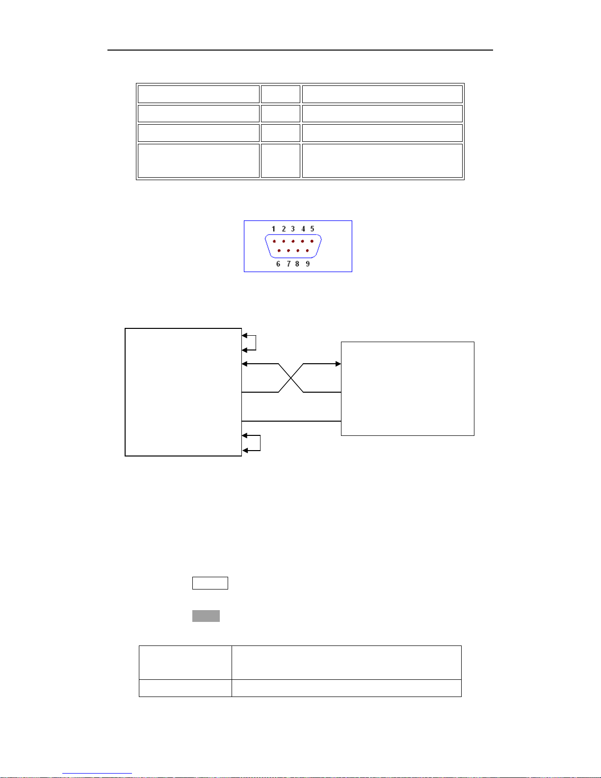
TX7410 only uses the smallest subset of the RS232C standard, the signal are listed as
Function Code
25 Pin Connector
Pin Number
9 Pin Connector
Pin Number
Request To Send RTS 4 7
Clear To Send CTS 5 8
Data Set Ready DSR 6 6
Data Carrier Detect DCD 8 1
Data Termina l Re ady DTR 20 4
Transmitted Data TXD 3 3
Received Data RXD 2 2
Signal Ground
Common
GND 7 5
Page 41
TX7410 Operation Manual
38
follows.
Function Code 9 Pin Connector Pin Number
Transmitted Data
TXD 3
Received Data
RXD 2
Signal Ground
Common
GND 5
TX7410’s RS232 interface may be different with the standard RS232C. The pin
configuration is shown as follows.
5.1.2 Communication with a computer
Diagram of connection to a controller.
DTR(4)
DSR(6)
RXD(2) (2) RXD
Computer
(controller) TXD(3) (3) TXD TX7410
GND(5) (5) GND
RTS(7)
CTS(8)
There may be some diff erence between TX7410 ’s RS232 interface and a sta ndar d RS232 C
interface. You can make the connection cable by yourself according the diagram or order
one from our company.
Note: Pin 4 and 6, pin 7 and 8 are shorted respectively at the end of controller.
When the RS232C interfa ce is used to communicate with a controller, RS232 bus mode
should be selected as follows.
1) Press SYSTEM menu key, the
System Config
page will be displayed.
2) Move the curso r to t h e
Bus Mode
field.
3) Press RS232 to select the bu s mode to R S232 bus mo de.
Serial Interface Specifications
Baud Rate 4800 bps,9600 bps,11520 bps,12800 bps,14400
bps,19200 bps,28800 bps,38400 bps
Date Bits 8 Bits
Page 42

TX7410 Operation Manual
39
Stop Bits 1 Bit
Parity Bit None
End of Sequence NL (ASCII Code 10)
Connector DB9
Software Prot ocol
1) The controller sends the command using the ASCII code with NL as the end
character. TX7410 executes the command after the end character NL is received.
2) The character received by TX7410 will be sent back to the controller again. The
controller will not send the next character until the last return character is
received correctively from TX7410 . If the controller cannot receive the character
sent back by TX7410 , the reasons may be as follows.
A. The serial interface is not connected correctly.
B. Check if the RS232 function is turned on and TALK ONLY function is
turned off.
C. When TX7410 is executing a bus command, TX7410 will not accept any
character through the serial interface at the same time and the
character sent by controller will be ignored. In order to make sure the
whole command is sent and received correctly, the character without a
return character should be sent again by the controller.
3) TX7410 sends information under following two conditions. The first is when a
character is received n or m a lly; TX7410 will send the character back as response .
The second is when a query command is received; TX7410 will send the query
response information.
4) Once a query command is received, TX7410 will send the query response
information immediately e ven if the whole com mand has n ot been e xecuted. So if
the command includes two queries, the controller should read the query
responses twice. One query is recommended to be included in a single comma nd.
5) A query response is sent out in ASCII codes with NL as the terminal character.
6) Several query responses will be sent continuously with 1ms interval. The
controller should be ready to receive the responses; otherwise the response
information will be lost.
7) The controller should receive the query response terminal character NL.
Otherwise you will confuse a terminal character NL with a returned character. At
the same time the controller should receive the last returned character before
receiving a query response.
Page 43

TX7410 Operation Manual
40
8) For some commands that will take a l ong time to ex ecute, f or example Correction
command, the controller should keep waiting to avoid the next command being
lost when TX7410 is executing the former command.
Sample Program for Serial Interface
The following is a C language sa mple progra m unde r DOS en vironment . The main fun ction
may be expanded by users, and the other sub functions teach you how to input or output
a character string via the RS232 interface.
#def i ne PORT 0
#include "dos.h"
#include "stdio.h"
#include "stdlib.h"
#include "ctype.h"
#include "conio.h"
void port_init( int port,unsigned char code );
int check_stat( int port ); /* read serial port state(16bit) */
void send_port( int port,char c ); /* send a character to s erial port */
char read_port( int port ); /* recive a character form serial port */
void string_wr( char *ps ); /* write a string to serial port */
void string_rd( char *ps ); /* read a string from serial port */
char input[256 ]; /* quary recieve bufer */
main()
{
port_init( PORT,0xe3 );/* initilize serial port:baud = 9600,no verify,1 bit stop,8 bit data
*/
string_wr( "trig:sour bus;*trg" );
string_rd( input );
printf( "\ n%s",input );
string_wr( "freq 10khz" );
string_wr( "func:imp:apar cs;bpar d" );
string_wr( "voltage:level 0.3v" );
}
/* write string to serial port */
void string_wr( char *ps )
{
unsigned char c;
int m,n;
while( check_stat(PORT) & 256 ) read_port( PORT );/* read data until null */
for( m = 1000;m;m-- ) /*communication handshake:wait until ready*/
Page 44

TX7410 Operation Manual
41
{ send_port( PORT,0xaa );
for( n = 100;n; n-- )
{
delay( 2 ) ; /* wa it about 2ms */
if( kbhit() && ( getch() == 27 ) ) /* if escape key keypress */
{ printf( "\ nE20:Serial Port Wri te Cance led!" ) ;
exit(1);
}
if( check_stat(PORT) & 256 )
{ c = read_ port( PORT );
break;
}
}
if( n ) break;/*TX7410 /C not ready for receive*/
}
if( c != 0xcc )/*check receive*/
{ printf( "\ nE10:Serial Port HandShake Failure!" );
exit(1);
}
/*handshake success,begin send string:*/
for( ;*ps; )
{
send_port ( PORT,*ps++ );
delay(2);
}
send_port( PORT,'\ n' ) ;
delay(2);
}
/* read string f rom serial port */
void string_rd( char *ps )
{
unsigned char c,i;
for( i = 0;i < 255;i++ ) /* max read 256 characters */
{
while( ! (check_stat(PORT) & 256) ) /* wait serial recieve ready */
if( kbhit() && (getch( ) == 27) ) /* i f e sc a pe key keypress */
{ printf( "\ nE21:Serial Port Read Canceled!" );
exit(1);
}
c = read_po rt( PORT );
if( c == 0xcc ) continue;/*skip the more handshake characters*/
Page 45

TX7410 Operation Manual
42
if( c == '\ n' ) break;
*ps = c;
ps++;
}
*ps = 0;
}
/* send a c haracter to s erial port */
void send_port( int port,char c )
{
union REGS r;
r.x.dx = port; /* serial port */
r.h.ah = 1; /* int14 function1:send character */
r.h.al = c; /* character to be sent */
int86( 0x14,&r,&r );
if( r.h.ah & 128 ) /* check ah.7,if set by int86( 0x14,&r,&r ),mean trans error */
{ printf( "\ nE00:Serial port send error!" );
exit(1);
}
}
/* read a character from serial port */
char read_port( int port )
{ union REGS r;
r.x.dx = port; /* serial port */
r.h.ah = 2; /* int14 function2:read character */
int86( 0x14,&r,&r );
if( r.h.ah & 128 ) /* if ah.7 be set,mean trans error */
{ printf( "\ nE01:Seri a l port read error!" );
exit(1);
}
return r.h.al;
}
/* check the status of serial port */
int check_stat( int port )
{ union REGS r;
r.x.dx = port; /* serial port */
r.h.ah = 3; /* int14 function3:read status */
int86( 0x14,&r,&r );
return r.x.ax; /* ax.7 show seria l o peration, ax.8 show serial recive ready */
}
/* initialize the serial port */
void port_init( int port,unsigned char code )
Page 46
TX7410 Operation Manual
43
{ union REGS r;
r.x.dx = port; /* serial port */
r.h.ah = 0; /* int14 function0:initial serial port */
r.h.al = code; /* initialization code */
int86( 0x14,&r,&r );
}
5.2 GPIB Interface Introduction
5.2.1 GPIB connection
When configuring a GPIB system, the following restrictions must be adhered to.
The total length of cable in one bus system must be less than or equal to two meters
times the number of devic es conne cted on the bus ( the GPI B contr oller c ounts as one
device) and the total length of cable must not exceed 20 meters.
A maximum of 15 devices can be connected on one bus system.
There are no restrictions on how the cables are connected together. However, it is
recommended that no more than four piggyback connectors be stacked together on
any one device. The resulting structure could exert enough force on the connector
mounting to damage it.
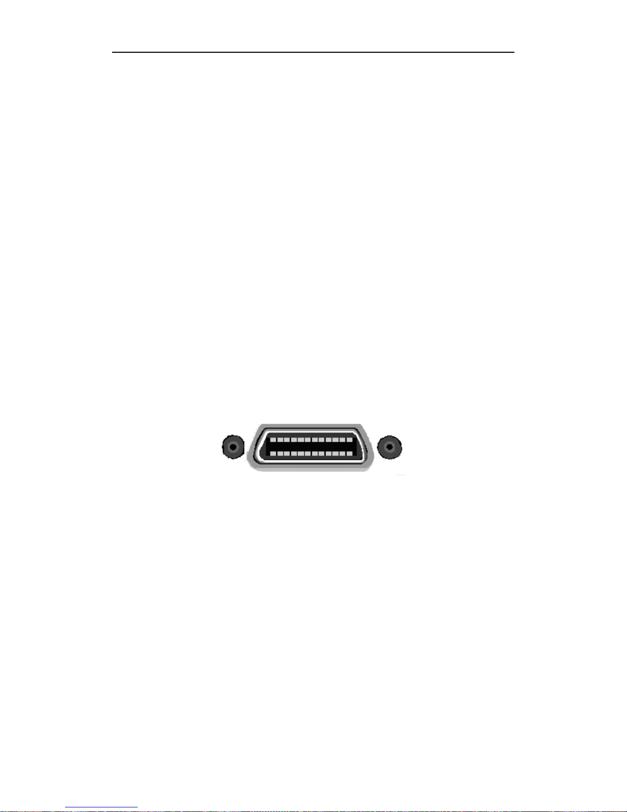
Figure 5-1 GPIB connection
Page 47
TX7410 Operation Manual
44
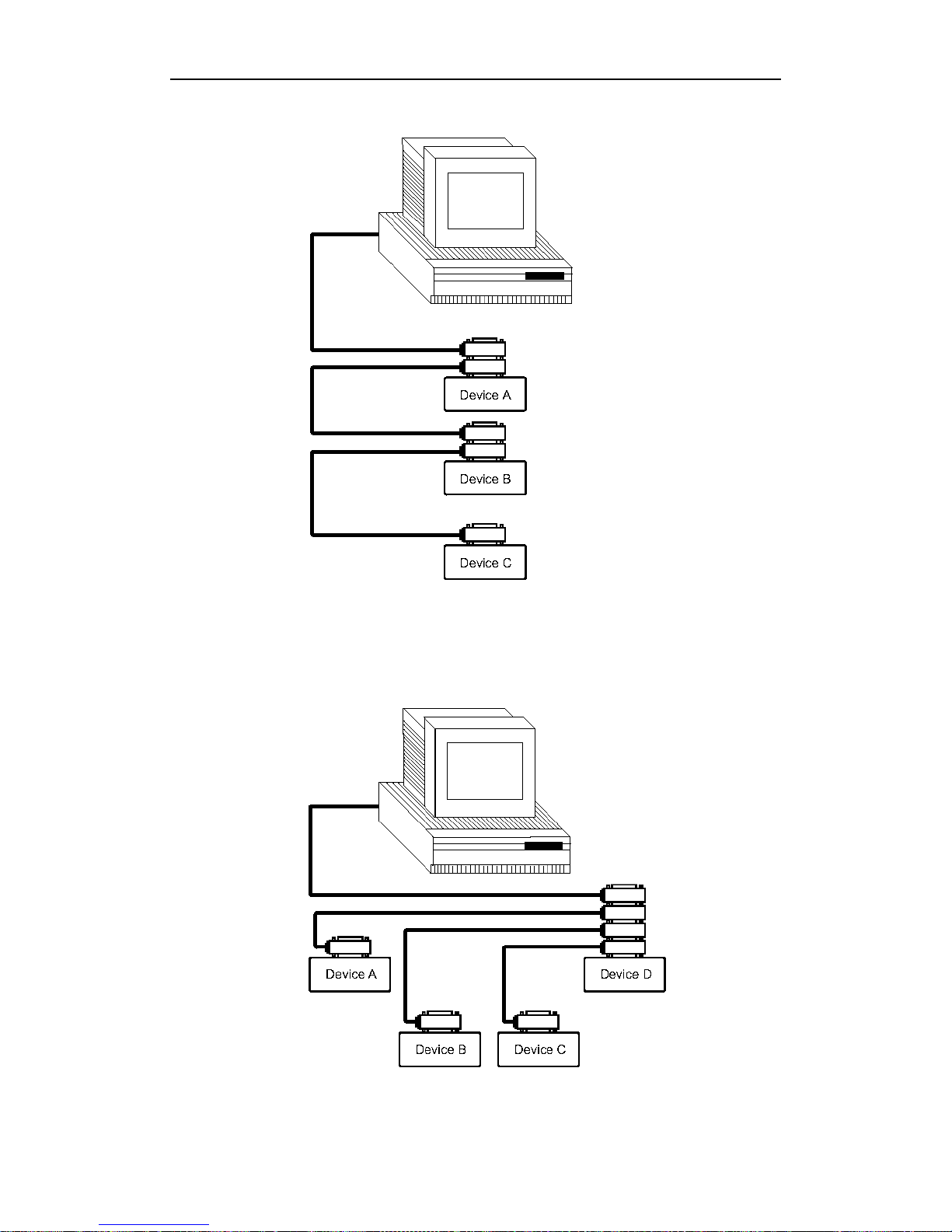
Typical GPIB System Interconnectio n-1
Figure 5-2 Typical GPIB System Interconnection-1
Typical GPIB S ys t e m Interconnection-2
Figure 5-3 Typical GPIB System Interconnection-2
Page 48

TX7410 Operation Manual
45
5.2.2 GPIB interface functions
TX7410 's GPIB functions are listed in the following table.
Code Function
SH1 Complete Source Handshake capability
AH1 Complete Acceptor Handshake capability
T3 Basic Talker; Talk-Only; unaddressed if MLA; no serial poll
L3 Basic Listener; unaddressed if MTA; no Listen Only
RL1 Remote/Loc a l capabil ity
DC1 Device Clear capability
DT1 Device Trigger capa bility
C0 No Controller capability
E1 Drivers are o pen-collector
5.2.3 GPIB addressing
TX7410 's GPIB address is stored in non-volatile memory and can be set to any address
from 0 to 30 by front panel key entry in the System Config page. When TX7410 is shipped
from the factory, the default GPIB address is 8. For more information, refer to “ 4.2.16
GPIB Address”.
5.2.4 GPIB bus function
TX7410 will respond to the following bus commands.
ABORT I/O (IF C)
ABORT I/O (IFC control line TRUE) halts all bus activity and deselects TX7410 .
DEVICE CLEAR (SDC or D CL)
This command can be used with an address to clear a particular device (SDC : selected
device clear) or used without an address (DCL : clears all devices). The Input buffer is
cleared, output data buffer is cleared and bit 4 (MAV bit) of the status byte is set to “0”,
when
TX7510
receives this command.
LOCAL (GTL)
LOCAL returns control of a listening device to front panel control.
REMOTE (RMT)
REMOTE sets TX7410 to the remote mode. When this command is sent, front panel with
the exception of LOCAL softkey will be disabled.
TRIGGER (GET)
It enables TX7410 to the TRIGGER bus command. This command may be sent to a
selected device or to all devices addressed as listeners on the GPIB bus. TX7410 must first
be addressed as a listener, second the trigger mode is set to the BUS trigger mode before
the trigger message is sent. This command is equal to the SCPI command TRIG+FETCh?
or the common command *TRG.
Page 49
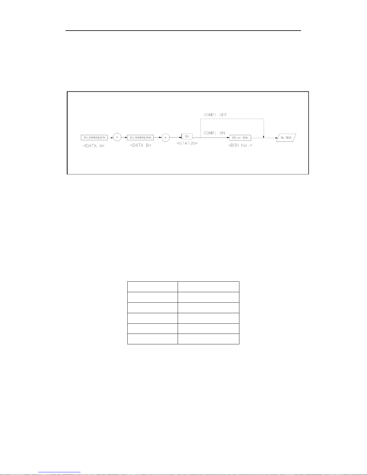
TX7410 Operation Manual
46
5.2.5 Data format
TX7410 outputs the meas ure ment results using the ASCII via t he GPIB bus. The Format 1
is used by
MeasDisplay
page,
BinNo. D isp
page a nd
Bin Count
page, whil e Fo rmat 2 is
used by
List Sweep
page. The two formats are described respectively as follows.
Figure 5-4 Data format 1
The <DATA A>, <DATA B>, and <BIN> formats are as follows.
<DATA A> and < DATA B> format:
The data output formats for <DATA A> (primary parameter's measurement data), and
<DATA B> (secondary parameter's measurement data) uses the 12 ASCII character fixed
length format as follows.
SN.NNNNNESNN
(S: +/-, N: 0 to 9, E: Exp o nent Sign)
<BIN> Format:
The <BIN No.> data shows the bin sorting results as follows.
Data Sorting Results
1 BIN 1
2 BIN 2
3 BIN 3
4 AUX_BIN
5 OUT_OF_BINS
The <BIN No.> data is output with the measurement data only when the comparator
function is set to ON.
Page 50

TX7410 Operation Manual
47
Chapter 6 Handler Interface
6.1 General Information
The handler interface outputs signals to indicate measurement completed, bin sorting
judgments of the comparator function, and Go/No-Go judgments of the list sweep
comparator function. The handler interf ace also has an input f or an e xternal trigger sig nal.
Using these signals, TX7410 can easily be combined with a component handler and a
system controller to fully automate component testing, sorting, and quality control data
processing to increase production efficiency. Table 9-1 lists the handler interface
specifications.
Specifications
Output signal
(Negative true,
open collector,
opto-isolated)
Decision output for
comparator function
Bin number, out of bins, and rejection status
Decision output for
list sweep
comparator function
IN/OUT at each sweep point and pass/fail for
the result of sequential comparisons
IDX Analog measurement complete
EOM
Full measurement complete.
Display time is not included on the BinNo Disp
page.
Display time is inc
luded on the List Sweep
page.
Input Signal
(Opto-isolated)
TRIG External Trigger, Pulse width≥1μs
Table 6-1 Specifications of handler interface
6.2 Signal’s Definition
Pin No. Signal Name Description
1
2
3
/BIN1
/BIN2
/BIN3
Bin sorting judgments.
All bin sorting signal outputs are opto-
isolated open
collector.
4
5
6
7
NC
NC
NC
NC
No Connection
No Connection
No Connection
No Connection
Page 51

TX7410 Operation Manual
48
8
9
NC
NC
No Connection
No Connection
10
11
/OUT
/AUX
Bin sorting judgments.
All bin sorting signal outputs are opto-isolat
ed open
collector.
12
13
/TRIG
/TRIG
External Trigger:
TX7410
is triggered on the rising ed ge of a p ulse ap plied t o
this pin when the trigger mode is set to EXT mode.
14
15
EXV2
EXV2
External DC voltage 2:
DC voltage supply pins for DC isolated control signals
(/TRIG, /IDX, /EOM). Setting of internal jumpers must be
changed when using an internal voltage supply.
16
17
18
VCC Internal voltage supply (maximum 100 mA)
Setting of internal jumpers must be changed when using an
internal voltage supply.
19 /PHI Primary Parameter High Rej ect:
The measurement value is greater than the high limit value
of BIN1–BIN3.
20 /PLO Primary Parameter Low Reject:
The measurement value is less than the low limit value of
BIN1-BIN3.
21 /SREJ Secondary Parameter Reject:
The
measurement value is not within the range of the
secondary parameter limit.
22
23
24
25
26
NC
NC
NC
NC
NC
No Connection
No Connection
No Connection
No Connection
No Connection
27
28
EXTV1
EXTV1
External DC voltage 1:
DC voltage supply pins for DC isolate
d open collector
outputs, /BIN1-/BIN3, /AU X, /OUT, /PHI, /PLO, /SREJ. The
setting of internal jumpers must be changed when us ing the
internal voltage supply.
29 NC No Connection
30 /IDX
/IDX signal is asserted when an analog measurement is
completed and
TX7410
is ready for the next DUT to be
connected to the UNKNOWN terminals. The measurement
data, however, is not valid until /EOM is asserted.
31 /EOM End of Measurement:
This signal is asserted when the measurement data and
comparison results are valid.
32 COM2 Common for EXTV2
Page 52
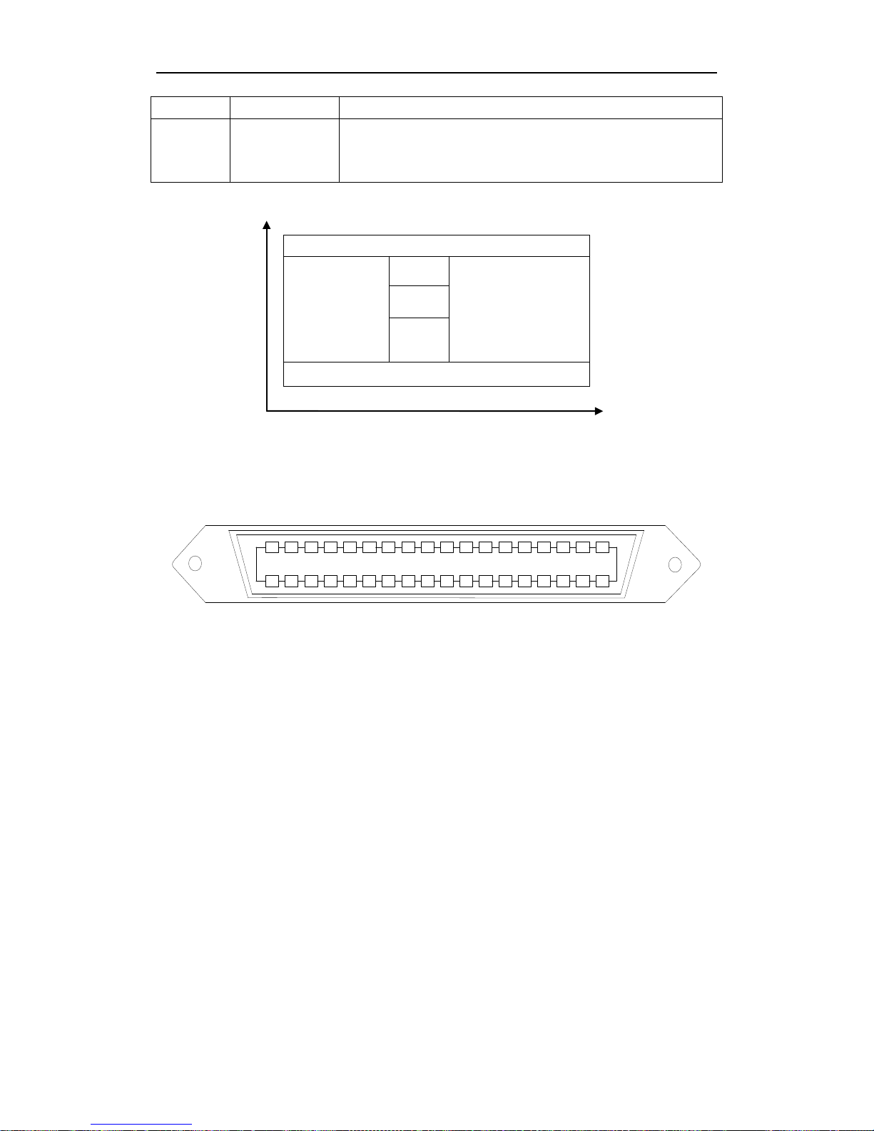
TX7410 Operation Manual
49
33 COM2
34
35
36
COM1
COM1
COM1
Common for EXTV1
Table 6-2 Pin assignments for comparator function
Primary
Parameter
Secondary Parameter
Figure 6-1 /PHI, /PLO, /SREJ signal’s area example
35
34
33
32
31
30
29
28
27
36
26
25
24
23
22
21
20
19
17
16
15
14
13
12
11
10
9
18
8
7
6
5
4
3
2
1
/BIN1
/BIN2
/BIN3
NC
NC
NC
NC
NC
NC
/OUT
/AUX
/TRIG
/TRIG
/EXV2
VCC
VCC
VCC
/PHI
/PLO
/SREJ
NC
NC
NC
NC
NC
EXV1
NC
/IDX
/EOM
COM2
COM2
COM1
COM1
COM1
/EXV2
EXV1
Figure 6-2 Pin assignment for handler interface connector
PHI(OUT)
SREJ(AUX)
BIN 1
SREJ(AUX)
BIN 2
BIN 3
PLO(OUT)
Page 53
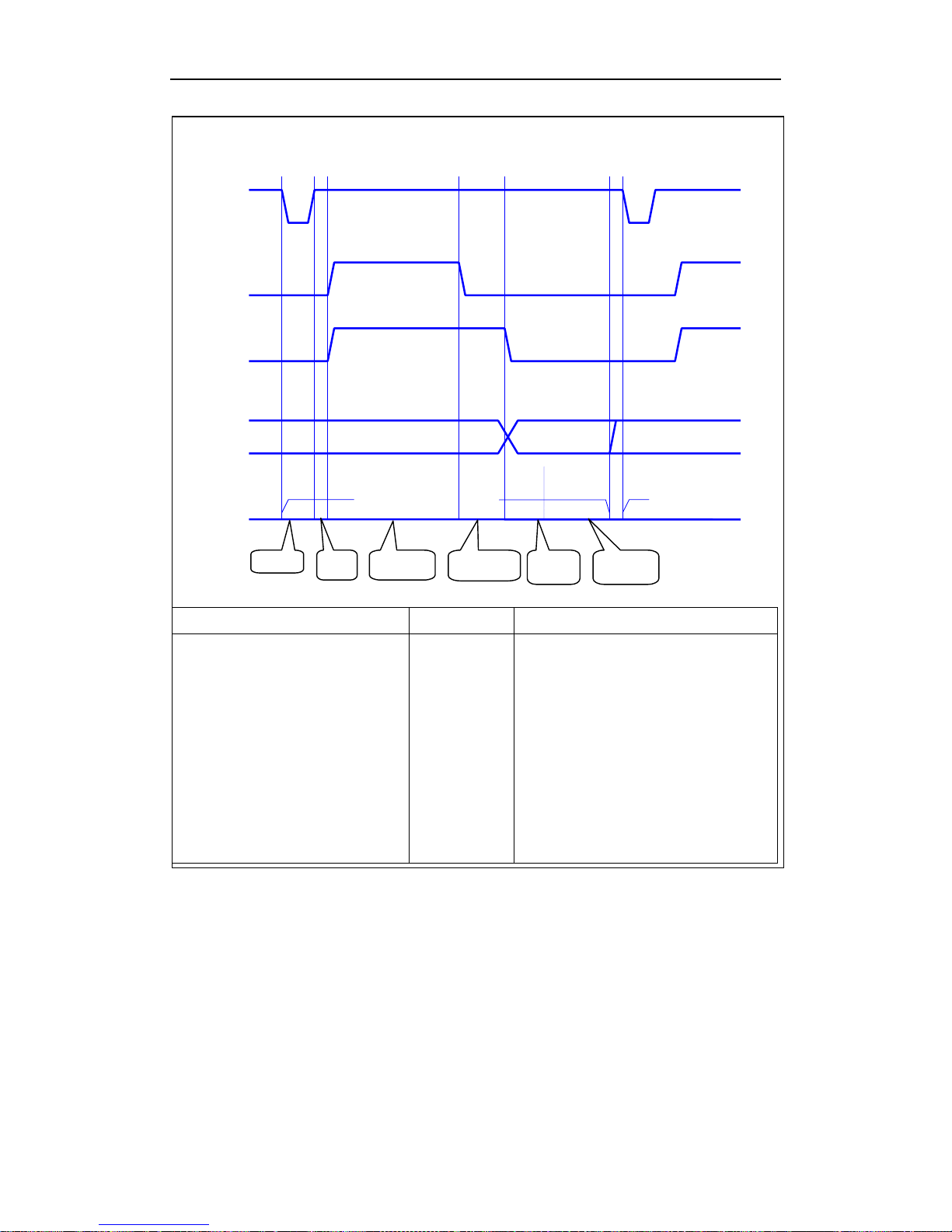
TX7410 Operation Manual
50
Time Min. value Max. value
T1 Trigger pulse width
T2 Measurement start and setup
T3 Trigger waiting time
Measurement time——fast
——middle
——slow
Calculating and hanlding time
Display time
Measurement delay
10us
200us
0us
16ms+9T
80ms+9T
320ms+4T
10ms
15ms
0ms
--2ms
Next valid trigger will be memorized
since this measurement.
20T at f<1kHz
20T at f<1kHz
320ms+9T at f≥1kHz
---
--60s
Figure 6-3 Time diagram
6.3 Electrical Characteristics
6.3.1 DC Isolated Outputs
Each DC output (pins 1 through 11, pins 19 through 21, pins 30 through 31) is isolated
using an open collector output opto-coupler. The output voltage of each line is set by a
pull-up resistor on the handler interface board. The pull-up resistors can be connected to
/TRIG
/IDX
/EOM
Result
Time
previous valid data valid data
hold or clear
T1 T2
T3
one measurement period
next period
delay
setup
measurem
ent time
calculating &
comparing
display
time
measurem
ent delay
triggger
Page 54
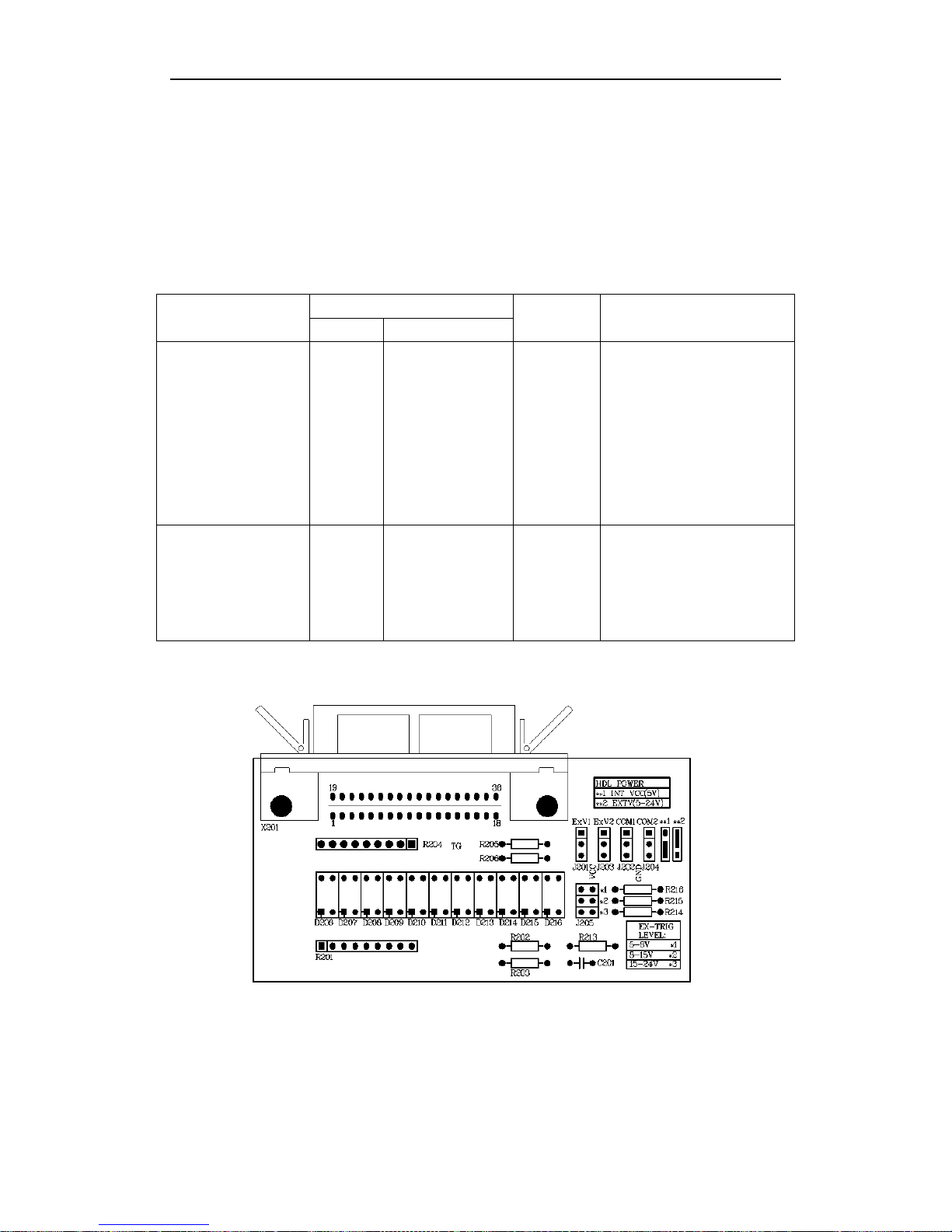
TX7410 Operation Manual
51
the internally supplied voltage (+5V), or to an externally applied voltage ( EXTV: +5V to
+24V) by setting jumpers.
The electrical characteristics of the DC isolated outputs are divided into two types (See
Table 6-4).
Since the power source for the Comparison Output a nd Control Output signals are different ,
two circuit commons (COM1, COM2) are made available.
Figure 6-4 DC Isolated output electrical characteristics
Figure 6-5 Position and setup of HANDLER interface’s jumpers
Output Signals
Voltage Out put Rating
Maximum
Current
Circuit Common
Low High
Comparison
Signals
/BIN1 - /BIN3
/OUT
/AUX
/PHI
/PLO
/SREJ
≤0.5V +5V to +24V 6mA
Internal pull-
up voltage:
Circuit common (GND)
External voltage (EXTV1):
COM1
Control Signals
/IDX
/EOM
≤0.5V +5V to +24V 6mA
Internal pull-
up voltage:
Circuit common (GND)
External voltage (EXTV2):
COM2
Page 55
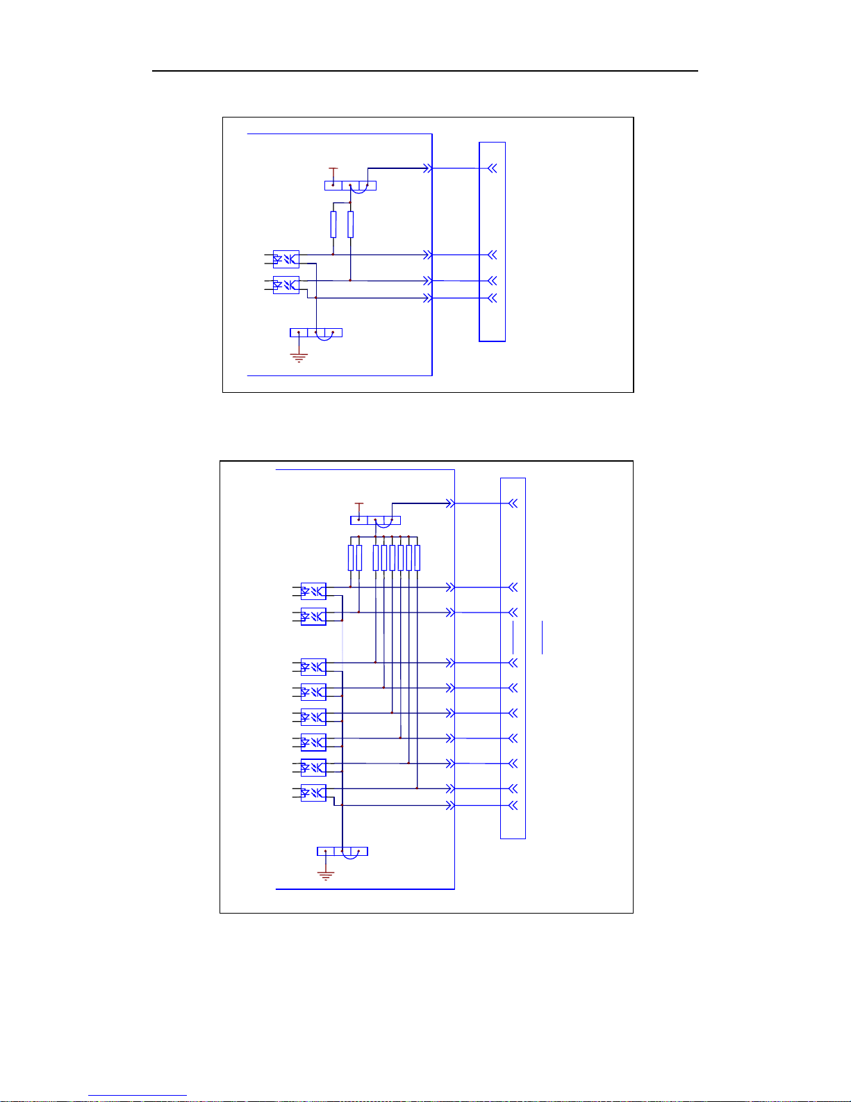
TX7410 Operation Manual
52
*Default jumper wire position
Figure 6-6 Simplified diagram of the control output signals
*Default jumper wire position
Figure 6-7 Simplified diagram of the sorting output signals
VCC
J202
J201
HANDLER interface board
EXV1
/BIN1
/BIN2
/BIN9
/OUT
/AUX
/PHI
/PLO
/SREJ
COM1
HANDLER interface connector
27,28
1
2 9 10 11 19 20 21
34,35,36
pull-up resistance 4.7k
internal +5V power
grounding
*
*
VCC
J204
J203
HANDLER interface board
EXV2
/IDX
/EOM
COM2
HANDLER interface connector
14,15
30 31
32,33
internal +5V power
grounding
*
*
pull-up resistance 4.7k
Page 56
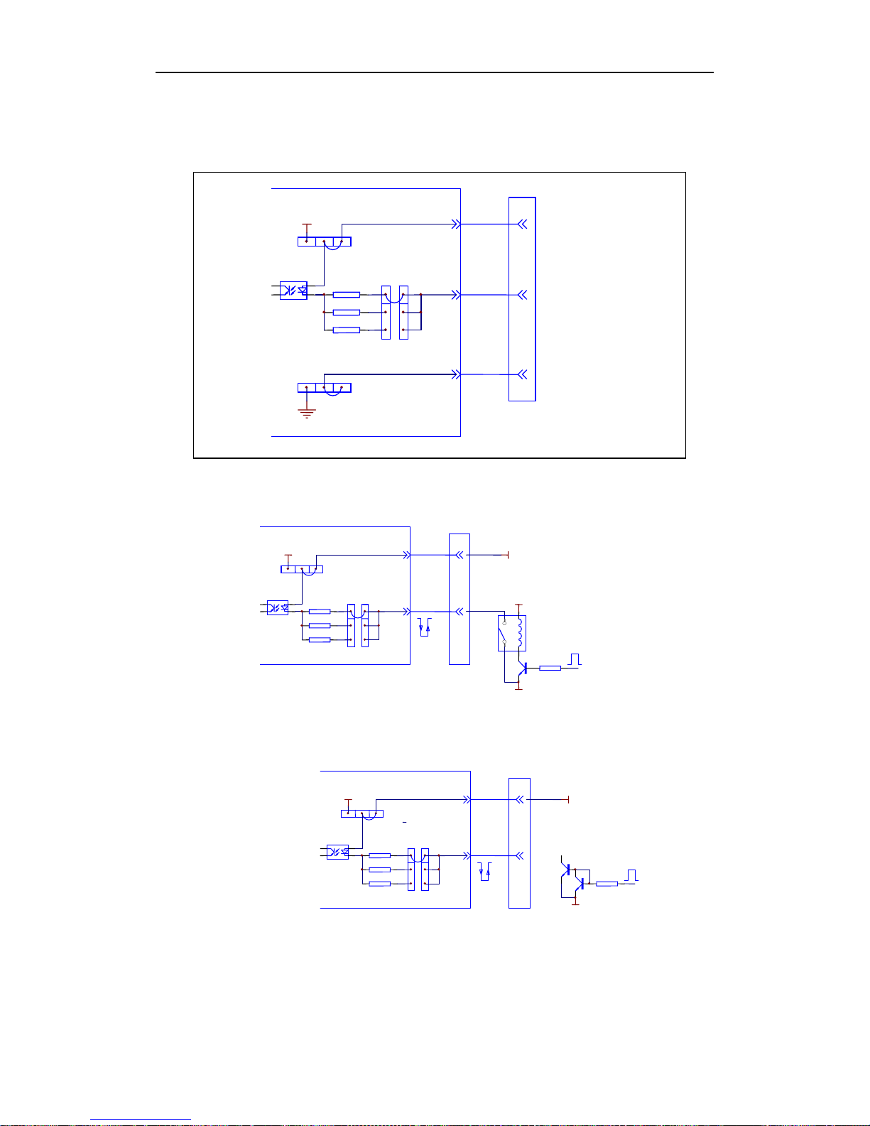
TX7410 Operation Manual
53
6.3.2 DC Isolated Input
*Default jumper wire position
Figure 6-8 Simplified d igr am of HANDLER interface’s trigger input signals
Figure 6-9 Relay to control trigger
Figure 6-10 Reverser to drive and trigger signals
680
1.2k
VCC
J205
J203
EXV2
/TRIG
14,15
12,13
trigger resistance
with limit current
internal +5V power
*
*
2.2k
EXV
EXV
COM
trigger
edge
680
1.2k
VCC
J205
J203
EXV2
/TRIG
14,15
12,13
trigger resistance
with limit current
internal +5V power
*
*
2.2k
EXV
COM
trigger
edge
680
1.2k
VCC
J205
J203
HANDLER interface board
EXV2
/TRIG
COM2
HANDLER interface connector
14,15
12,13
32,33
trigger resistance with
limit current
Iternal +5V power
*
*
2.2k
J204
grounding
*
Page 57

TX7410 Operation Manual
54
Chapter 7 Packing & W arranty
7.1 Packing
The contents are listed as follows:
Description Quantity
1. TX7410 LCR Meter 1
2. TX7003 Test F ixture 1
3. TX7000 Kelvin Test Cable 1
4. TX26010 Shorting Plate 1
5. Three-Wire Power Cord 1
6. 1A Fuse 2
7. Operation Manual 1
8. Test Report 1
Check the contents when you receive the instrument. If the contents are incomplete, if
there is mechanical damage or defect, or if the instrument does not p ass the power-on
self-tests, please contact our company or business department immediately (IEEE488
interface is optional).
7.2 Warranty
This DAE KWANG instrument product is warranted against defects in material and
workmanship f or a perio d of two years fro m the date of shipment or pu r chase. During the
warrant y period, DAE KW ANG wi ll, at its option, eithe r repair or repla ce the products which
prove to be defective. And warranty card is required when the product needs repairing.
And all DAE KWANG products are warranted for service of lifetime maintenance.
The foregoing warranty shall not apply to defects resulting from improper or inadequate
maintenance by Buyer, Buyer-supplied software or interfacing, unauthorized modification
or misuse, operation outside of the environmental specifications for the product, or
improper site preparation or maintenance.
 Loading...