

Page 1

TX5012 Series Operation Manual Ver1.0
◇1
OPERATION MANUAL
TX5012 series
Withstanding Voltage/Insulation
Resistance Tester
DAE KWANG T&M CO.,LTD
http://www.kdk.co.kr
TEL :02)2617-0787
Page 2

TX5012 Series Operation Manual Ver1.0
◇2
Content
CHAPTER 1 SETUP................................................................................................................ ...........4
1.1 UNPACKING .................................................................................................................................4
1.2 PRECAUTIONS FOR INSTALLATION ...............................................................................................4
1.3 PRECAUTIONS FOR MOVING .......................................................................................................6
1.4 CHECK POWER SUPPLY AND FUSE..............................................................................................6
1.4.1 Switch power voltage.......................................................................................................6
1.4.2 Checking and replacing fuse...........................................................................................7
1.5 CONNECTING THE AC POWER CORD .........................................................................................7
1.6 GROUNDING ................................................................................................................................7
1.7 CHECKING OPERATIONS.............................................................................................................8
1.8 OTHER SPECIFICATIONS .............................................................................................................9
CHAPTER 2 PRECAUTIONS ON HANDLING...........................................................................10
2.1 PROHIBITED OPERATIONS ........................................................................................................10
2.2 ACTION WHEN IN EMERGENCY.................................................................................................11
2.3 PRECAUTIONS ON TESTING ......................................................................................................11
2.4 DANGEROUS STATES OF FAILED TESTER ................................................................................12
2.5 DAILY CHECKING ......................................................................................................................12
CHAPTER 3 INTRODUCTION......................................................................................................13
3.1 INSTRUCTION OF FRONT PANEL ................................................................................................13
3.2 INSTRUCTION OF REAR PANEL ..................................................................................................15
CHAPTER 4 BASIC OPERATION.................................................................................................16
4.1 GENERAL PARAMETER SETTING................................................................................................16
4.2 DISPLAYED INFORMATION .........................................................................................................25
Page 3

TX5012 Series Operation Manual Ver1.0
◇3
4.3 OPERATION PROCEDURE AND STEP..........................................................................................29
4.4 KEYBOARD LOCK.......................................................................................................................31
CHAPTER 5 PARAMETER INSTRUCTION...............................................................................32
5.1 WITHSTANDING VOLTAGE TEST PARAMETER.............................................................................32
5.2 INSULATION RESISTANCE PARAMETER......................................................................................33
5.3 INTERFACE INSTRUCTION..........................................................................................................35
CHAPTER 6 CALIBRATION AND DAILY MAINTENANCE......................................................37
6.1 CLEAN .......................................................................................................................................37
6.2 CHECK.......................................................................................................................................37
6.3 MAINTENANCE...........................................................................................................................37
6.3.1
Calibration ........................................................................................................................38
Page 4
TX5012 Series Operation Manual Ver1.0
◇4
Chapter 1Setup
This chapter describes the procedures from unpacking to installation to
operation checking.
1.1 Unpacking
Upon receiving the product, confirm that the necessary accessories are included and
have not been damaged in transit. Should any damage or shortage be found, please
contact DAE KWANG T&M distributor/agent.
Items Quantity
TX5012/D/DI withstand voltage/insulation tester
1
TX90003B withstanding-voltage test lead wires 1
TX90004 withstanding-voltage ground lead wires 1
3A Fuse 2
AC Power cord 1
Operation Manual 1
Tes t R e p o r t 1
Servicing card 1
Accessories ordered by customer 1
1.2 Precautions for Installation
Be sure to observe the following precautions when installing the tester.
■
Do not use the tester in a flammable atmosphere.
To prevent explosion or fire, do not use the tester near alcohol, thinner, or other
combustible materials, or in an atmosphere containing such vapors.
■
Avoid locations where the tester is exposed to high temperatures
or direct sunlight.
Do not locate the tester near a heater or in areas subject to drastic temperature
changes.
Operating temperature range: 5 °C to +35 °C
Storage temperature range: -20 °C to +70 °C
■
Avoid humid environments.
Page 5

TX5012 Series Operation Manual Ver1.0
◇5
Do not locate the tester in a high-humidity environment—near a boiler, humidifier, or
water supply.
Operating humidity range: 20 % to 80 % RH (no dew condensation permitted)
Storage humidity range: 90 % RH or less (no dew condensation permitted)
Condensation may occur even within the operating humidity range. In that case, do not
start using the tester until the location is completely dry.
Do not locate the tester in a high-humidity environment—near a boiler, humidifier, or
water supply.
Operating humidity range: 20 % to 80 % RH (no dew condensation permitted)
Storage humidity range: 90 % RH or less (no dew condensation permitted)
Condensation may occur even within the operating humidity range. In that case,
do not start using the tester until the location is completely dry.
■
Do not place the tester in a corrosive atmosphere.
Do not install the tester in a corrosive atmosphere or one containing sulfuric acid mist
or the like. This may cause corrosion of various conductors and imperfect contact
with connectors, leading to malfunction and failure, or in the worst case, a fire.
■
Do not locate the tester in a dusty environment.
Dirt and dust in the tester may cause electrical shock or fire.
■
Do not use the tester where ventilation is poor.
This tester features a forced-air cooling system. Provide sufficient space for the air
inlet on the lateral side and the air outlet on the rear side to allow air to flow.
■
Do not place the tester on a tilted surface or in a location subject
to vibrations.
If placed on a non-level surface or in a location subject to vibration, the tester may fall,
resulting in damage and injury.
■
Do not use the tester in locations affected by strong magnetic or
electric fields.
Operation in a location subject to magnetic or electric fields may cause the tester to
malfunction, resulting in electrical shock or fire.
■ Do not use the tester in locations near a sensitive test instrument
or receiver
Operation in a location subject, may cause such equipment may be affected by noise
generated by the tester.
Page 6
TX5012 Series Operation Manual Ver1.0
◇6
At a test voltage exceeding 3 kV, corona discharge may be generated to produce
substantial amounts of RF broadband emissions between grips on the test leadwire.
To minimize this effect, secure a sufficient distance between alligator clips. In
addition, keep the alligator clips and test lead wire away from the surfaces of
conductors (particularly sharp metal ends)
1.3 Precautions for Moving
When moving the tester to the installation site or otherwise transporting it, take the
following precautions:
■
Before moving the tester, turn off the power switch.
Transporting the tester with its POWER switch on can lead to electric shock and
damage.
■
When moving the tester, Disconnect all wires from it.
Moving the tester without disconnecting the cables may result in breakage of the
wire or injury due to the tester tipping over.
1.4 Check power supply and fuse
1.4.1 Switch power voltage
!
WARNING:This instrument is designed to operate from the overvoltage category II.
Do not operate it from the overvoltage category III or IV.
Before turning on the power, make sure of the fuse and the source voltage agree with
the LINE-VOLTAGE RANGE switch on the rear panel.
Nominal voltage range (allowable voltage range):
100 V to 120 V AC (85 V to 132 V AC)
200 V to 240 V AC (170 V to 250 V AC)
Allowable frequency range: 47 Hz to 63 Hz
!
WARNING To prevent malfunctions, be sure to operate within the line-voltage range.
Page 7
TX5012 Series Operation Manual Ver1.0
◇7
1.4.2 Checking and replacing fuse
!
WARNING To prevent electric shock, before checking or replacing the fuse, be sure
to turn off the POWER switch and unplug the AC power cord.
Make sure that the fuse used conforms to the instrument specifications, including shape,
rating, and characteristics. Using a fuse with different rating or short-circuiting, the fuse
holder will damage the instrument.
1. Turn off the POWER switch, and unplug the AC power cord.
2. On the rear panel, remove the fuse holder, by pushing it inward and unscrewing it
counterclockwise using a screwdriver.
3. In accordance with the fuse rating specified below, check the fuse type and replace
the fuse.
4. Following the above steps in the reverse order, reinstall the fuse holder.
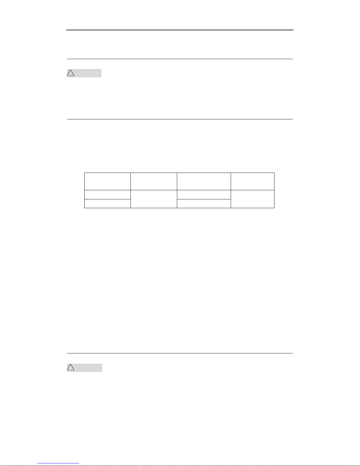
Output voltage
range
Frequency range Fuse type Max.power
100-120V 3A
200-240V
150VA
1.5 Connecting the AC Power Cord
The power cord that is provided varies depending on the destination for the product at
the factory-shipment.
Do not use the AC power cord provided with the product as a AC power cord for
other instruments.
Connection procedure:
1. Confirm that the supply voltage is within the line voltage range of the tester.
2. Confirm that the POWER switch on the tester is off.
3. Connect the AC power cord to the AC LINE connector on the rear panel.
Use the provided power code or power code that is selected by qualified personnel.
4. Plug in the AC power cord.
1.6 Grounding
!
WARNING Be sure to connect the tester to an electrical ground (safety ground). If the
Page 8
TX5012 Series Operation Manual Ver1.0
◇8
output to a conveyer or peripheral device that is connected to an earth ground or a
nearby commercial power line is short-circuited without grounding, the tester chassis is
charged to an excessively high voltage, resulting in extreme danger.
This tester is designed as a Classy equipment (equipment protected against electric
shock with protective grounding in addition to basic insulation). Therefore, electric shock
may occur without proper grounding.
To ensure safety, be sure to ground the tester.
Choose either of the following two available methods of doing so:
1. Connect the AC power cord to a three-contact grounded electrical
outlet.
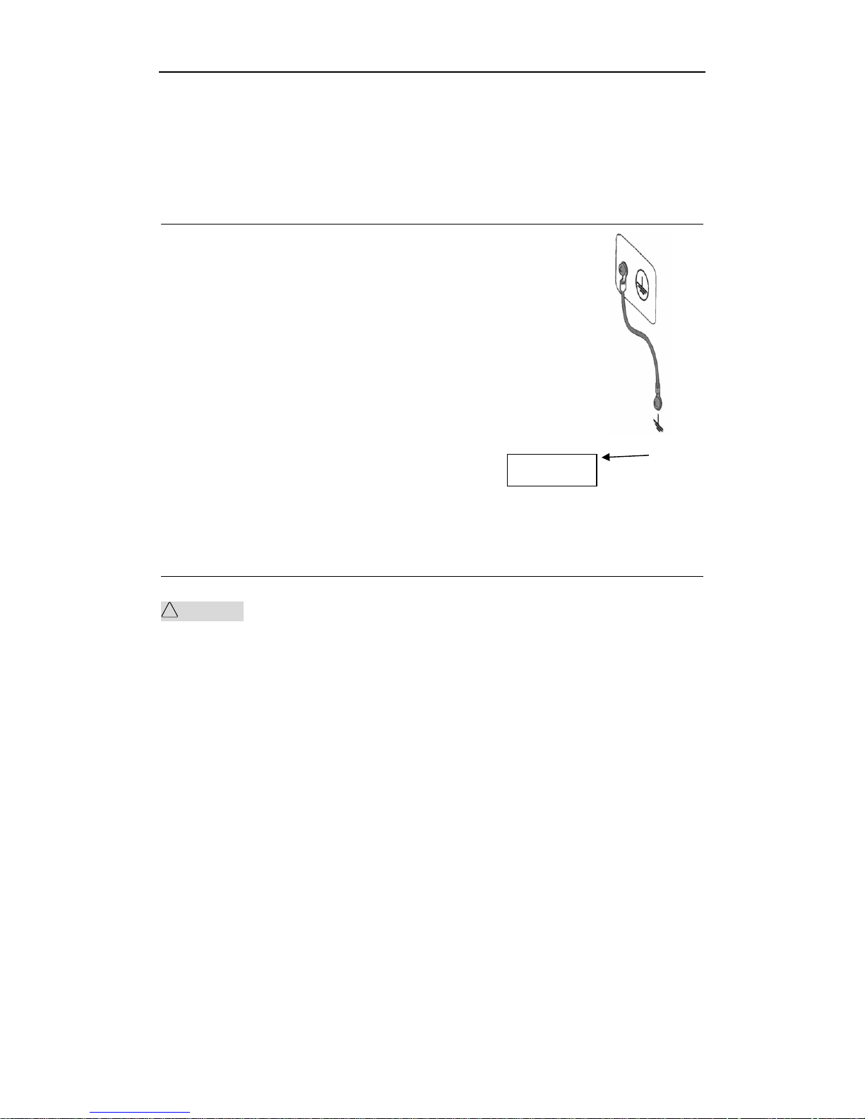
2. Connect the protective conductor terminal on the rear panel to the
earth ground.
Have specialized engineers select, manufacture, and install cables.
To ensure secure connection, use proper tools.
1.7 Checking Operations
!
WARNING Use the interlock jumper only to quickly cancel the protection status.
When using this tester, use the interlock function as much as possible to ensure a safe
operating environment. To use jigs in withstanding voltage or insulation resistance
testing, provide a cover or other means for the DUT to prevent electric shock by cutting
off the output when the cover is opened. It is also recommended that an enclosure be
provided around the operating area and that output be cut off every time the door is
opened.
Before turning on the power, confirm that the allowable voltage range indicated on the
power supply is the same as that indicated on the rear panel of the tester.
When the power is turned on, the tester lights all LEDs on the front panel and
self-diagnosis is started.
Before starting up the tester, confirm that all LEDs are on to ensure safety.
It is particularly dangerous to start a test when the DANGER lamp is broken.
Note that, in self-diagnosis, even when the DANGER lamp is lighting, no output or
Safe earth
Page 9

TX5012 Series Operation Manual Ver1.0
◇9
voltage is being generated.
!
CAUTION After turning off the POWER switch, wait several seconds before turning it
on. Turning the POWER switch on/off repeatedly with insufficient intervals may damage
the tester.
Checking procedure:
1. Confirm that the allowable voltage range indicated on the power supply is the same as
that indicated on the rear panel.
2. Confirm that the AC power cord is properly connected to the AC LINE connector on
the rear panel.
3. Plug in the AC power cord.
4. Turn on the POWER switch. Confirm that all LEDs on the front panel are lit.
Following the opening screen, display the ACW screen
5. Turn off the POWER switch.
6. Turn on the POWER switch again.RN
7. Following the opening screen, display the ACW screen and confirm that
the tester is kept in the READY status.
The above steps complete the checking procedure.
1.8 Other specifications
(1) Power:≤150VA
(2)
Dimensions(W*H*D):280mm*372mm*89mm;
(3) Weight:About 10kg
Page 10
TX5012 Series Operation Manual Ver1.0
◇10
Chapter 2Precautions on Handling
This chapter describes the precautions to be followed in the handling of this tester.
When using the tester, take utmost care to ensure safety.
!
WARNING The tester derives a 5 kV test voltage which can cause human
injury or death. When operating the tester, be extremely careful and observe the
cautions, warnings, and other instructions given in this chapter.
2.1 Prohibited Operations
■ Do not turn on/off the power repeatedly
After turning OFF the power switch, be sure to allow several seconds or more before
turning it ON again. Do not repeat turning ON/OFF the power switch rapidly. If you do
this, the protectors of the tester may not be able to render their protective functions
properly. Do not turn OFF the power switch when the tester is delivering its test
voltage–you may do this only in case of emergency.
■ Do not short the output to the earth ground
Pay attention so that the high test voltage line is not shorted to a nearby AC line or
nearby devices (such as conveyors) which are connected to an earth ground. If it is
shorted, the tester chassis can be charged up to the hazardous high voltage. Be sure to
connect the protective grounding terminal of the tester to an earth line. If this has been
securely done, even when the HIGH VOLTAGE terminal is shorted to the LOW terminal,
the tester will not be damaged and its chassis will not be charged up to the high voltage.
Be sure to use a dedicated tool when grounding the protective grounding terminal.
!
CAUTION The term "AC line" here means the line on which the tester is operating.
That is the line to whose outlet the AC power cable of the tester is connected. It
may be of a commercial AC power line or of a private-generator AC power line.
■ Do not apply an External Voltage
Page 11

TX5012 Series Operation Manual Ver1.0
◇11
Do not apply a voltage from any external device to the output terminals of the tester.
The analog voltmeter on the front panel cannot be used as stand-alone voltmeter.
They may be damaged if their output terminals are subject to an external voltage.
2.2 Action When in Emergency
In case of an emergency (such as electric shock hazard or burning of DUT), take the
following actions. You may do either (a) or (b) first. But be sure to do both.
1.Turn OFF the power switch of the tester.
2.Disconnect the AC power cord of the tester from the AC line receptacle.
2.3 Precautions on Testing
■ Wearing Insulation Gloves
When handling the tester, be sure to wear insulation gloves in order to protect yourself
against high voltages.
■
Precautions for Pausing Tests
When changing test conditions, press the STOP switch once to take precautions. If you
are not going to resume the test soon or if you are leaving the Test area, be sure to
turn-OFF the POWER switch.
■
Items Charged Up to Dangerous High Voltages
When in test, the DUT, test leadwires, probes, and output terminals and their
vicinities can be charged up to dangerous high voltages. Never touch them when in
test.
!
WARNING The vinyl sheaths of the alligator clips of the test leadwires which are
supplied accompanying the tester has no sufficient insulation for the high test voltages.
Never touch them when in test.
■ Matters to be Sure of After Turning-OFF Power
If you have to touch the DUT, test leadwires, probes, and/or output terminals and their
vicinities for re-connections or other reasons, be sure of the following two matters.
1. The analog voltmeter indicates “zero.”
2. The DANGER lamp has gone out.
Page 12

TX5012 Series Operation Manual Ver1.0
◇12
2.4 Dangerous States of Failed Tester
Typical possible dangerous states of the tester are as shown below and in which
cases the most dangerous situation that “the high test voltage remains delivered
and won't be turned off!” may occur. When this situation has occurred,
immediately turn OFF the power switch and disconnect the AC power cable from
the AC line receptacle.
•The DANGER lamp does not go out despite you have pressed the STOP
switch.
•The DANGER lamp does not light up despite the pointer of the analog
voltmeter is deflected indicating that the output voltage is being delivered.
Also when the tester is in other malfunctioning states than the above, there is a
possibility that the output voltage is delivered irrespective of your proper operating
procedure. Never use the tester when it has failed.
!
WARNING Keep the tester away of other people until you call our service engineer for
help.
Immediately call DAE KWANG T&M distributor/agent. It is hazardous for an unqualified
person to attempt to troubleshoot any tester problem.
2.5 Daily Checking
To avoid accidents, confirm at least the following before starting operation:
1. The tester is connected to an earth ground.
2. The coating of the high-voltage test lead wire is free from cracks, fissures, and
breakage.
3. The high-voltage test lead wire is not broken.
4. The tester generates FAIL signal when the ends of the low-voltage test lead wire and
high-voltage test lead wire are short-circuited.
Page 13
TX5012 Series Operation Manual Ver1.0
◇13
Chapter 3 Introduction
The basic operation of TX5012 series is described in this chapter. Please read this
chapter briefly before using TX5012 instrument.
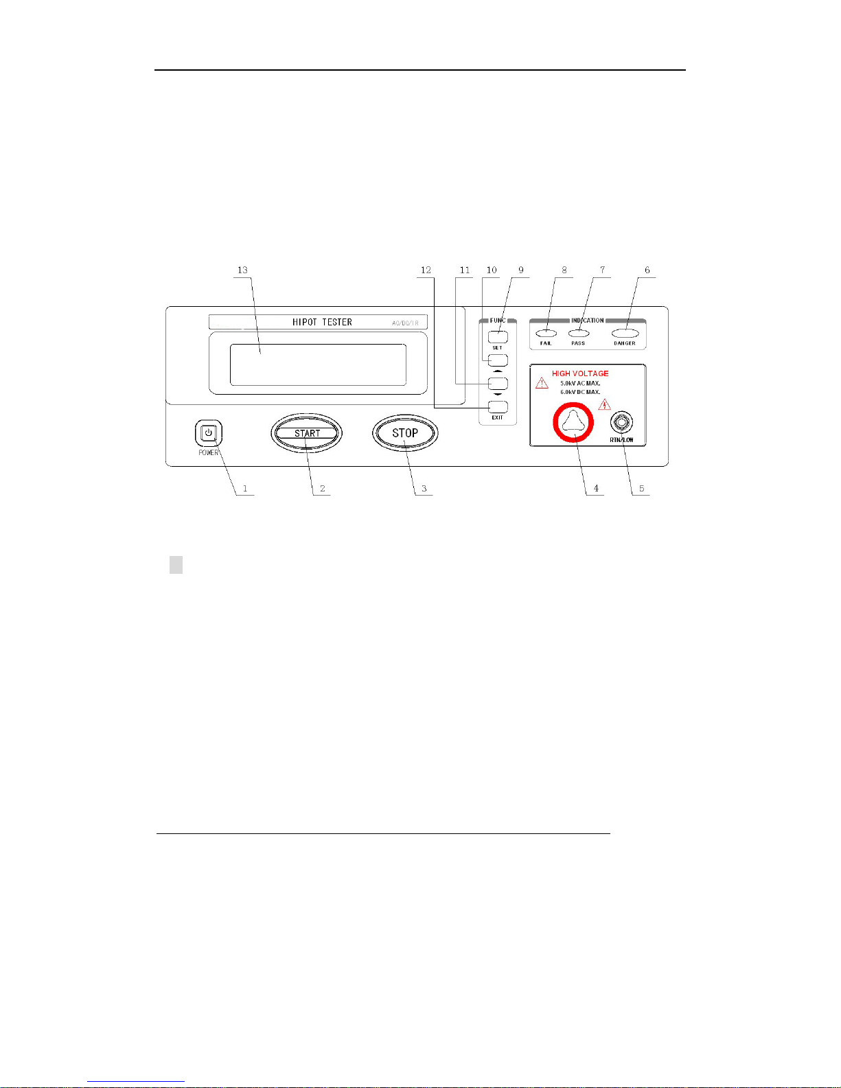
3.1 Instruction of front panel
Figure 3-1
⑴ (POWER)
Power switch
⑵ START
Setup start key for testing, once test starts, DANGER indicator is on.
⑶ STOP
For stop testing;
Or cancel PASS, FAIL,and its function is the same as EXIT key in setting mode or can
be the switch to quit setting mode.
⑷ (HIGH VOLTAGE)
The high terminal of output voltage.
Page 14

TX5012 Series Operation Manual Ver1.0
◇14
!
Warning:Don’t touch high voltage terminal in the process of testing.
Note:If external voltage is exerted in test terminal, then the internal circuit maybe
damaged.
⑸ (RTN/LOW)
Test low voltage terminal in back circuit.
⑹ DANGER indicator
In the process of testing, it lights in output voltage.
⑺ PASS
Indicate a test result, it lights in PASS
⑻ FAIL
Indicate a test result, it lights in FAIL.
⑼ SET
Operation key for selecting setting mode and memory group, test item, AC or DC
withstanding voltage test and its parameter setting, also insulation resistance test
and its parameter setting. It can also be the lock key
⑽ “∧”UP
In setting mode, it is used as the function key to select function and input each
parameter value, and as output voltage up-adjusting key in withstanding voltage test.
⑾ “∨”DOWN
In setting mode, it is used as the function key to select function and input each
parameter value, and as output voltage down-adjusting key in withstanding voltage
test.
⑿ EXIT
Function key to exit setting mode.
⒀
LCD displayer
16 digits×2 line backlighting LCD displayer.
Page 15
TX5012 Series Operation Manual Ver1.0
◇15
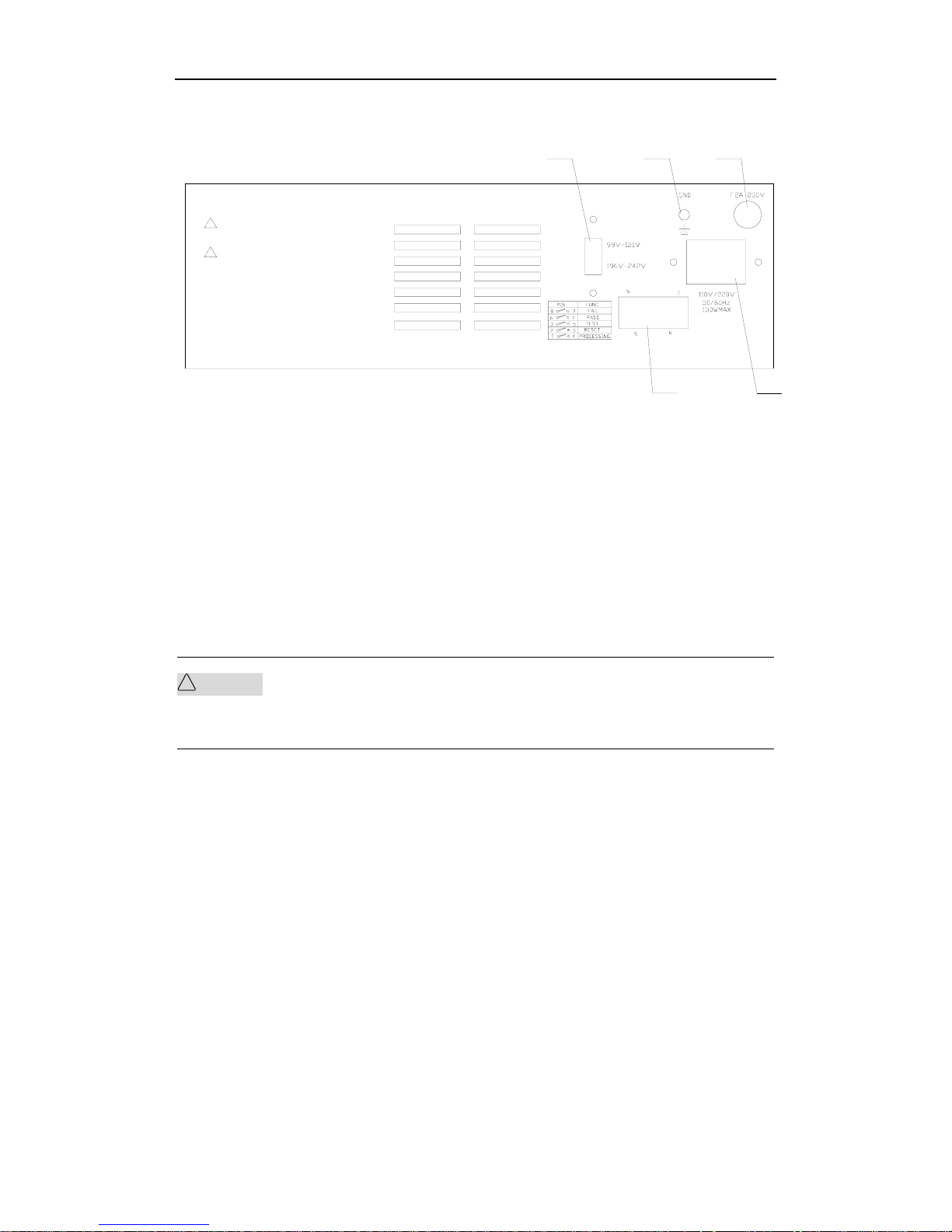
3.2 Instruction of rear panel
!
WARNING:FOR CONTINUED PROTECTION AGAINST FIRE HAZARD
REPLACE ONLY WITH THE SAME TYPE AND RATING OF FUSE AS
SPECIFIED FOR THE LINE VOLTAGE BEING UTILIZED.
CAUTION:NO OPERATOR SERVICEABLE PARTS INSIDE
REFER SERVICING TO QUALITIFIED PERSONNEL.
POLLUTION DEGREE 2
INSTALLATION CATEGORY
II
!
1
543
2
Figure 3-2
⑴ PLC remote signal terminal
It is a standard 9 PIN D terminal board,provides(N.O.) to remote monitor signal of
PASS、FAIL and PROCESSING and connection point of TEST、RESET.
⑵ Input power socket
Standard IEC 320 power socket,which can accept standard NEMA plug.
⑶ Input power fuse board
Turn off power switch then change fuse with same standard.
!
Warning:Please note if the model of the fuse meet the range of supplied voltage
before charging.
⑷
(GND) terminal
Please be sure to ground well to protect operator.
⑸ Input voltage selecting switch
Select input power voltage,down is 110V, up is 220V,the default setting is in 220V.
Page 16
TX5012 Series Operation Manual Ver1.0
◇16
Chapter 4 Basic operation
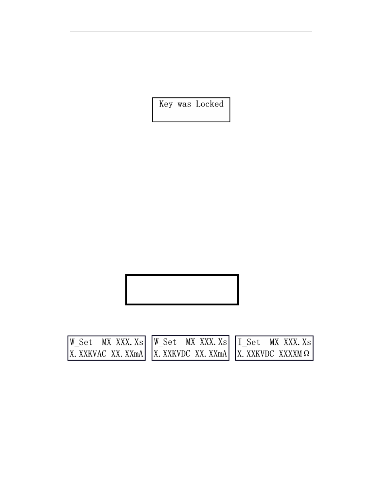
93 series Hipot tester has the key-lock function. Press SET key and turn on power switch
to enter parameter setting. If only the power is on, then the keyboard is locked, now
press SET key, the displayer will display:
So the key has to be unlocked, then set parameter.
“SET” is for setting parameter,and it will transfer to the turning key of parameter item
automatically, press SET once, the parameter setting will turn to the next item, and the
setting parameter will save into storage. The test parameter or mode in storage will be
kept after input power is off.
In the parameter setting mode,“∧” and “∨” are used as operation key for selecting
function and input key of parameter value.
In the process of parameter setting, you can press “EXIT” to exit this mode if you don’t
need to reset all parameters.
4.1 General parameter setting
After opening input power switch, LCD will display:
Now the procedure will enter the setting parameter of last test,LCE will display:
or or
W_Set: W_Set: I_Set:
MX: 1-5 MX: 1-5 MX: 1-5
TX5012
VER:2.0
Page 17
TX5012 Series Operation Manual Ver1.0
◇17
XXX.Xs:Time set XXX.Xs:Time set XXX.Xs:Delay time set
X.XXkVAC:AC voltage set X.XXkVDC:DC voltage set X.XXkVDC:DC voltage set
XX.XXmA:LC hi-limit set XX.XXmA:LC HI-limit set XXXXMΩ:IR low-limit set
Withstanding test parameter set
The withstanding voltage parameter is set by using SET key,press once to enter the
next parameter item,and the sequence is (Memory) set, test item selection, AC or DC
withstanding voltage selection, output voltage set, leakage current hi-limit set, leakage
current low-limit set, rise test time set, test time set, output frequency selection(There is
no such item in DC W_test), arc current sensitivity set.
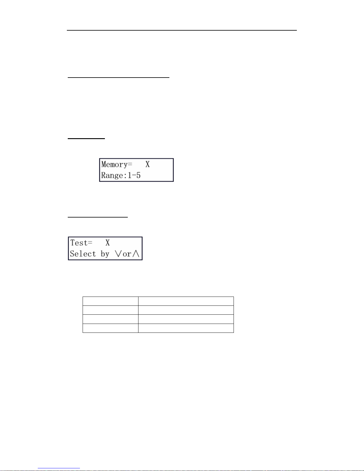
Memory set
Press SET key,the procedure will enter memory set mode automatically, and LCD will
display
:
Please use “∧” or “∨” to input number in parameter set procedure,there are five groups
in memory group.
Test item selection
When memory set is over, press SET key,the procedure will enter“Test item” mode and
LCD will display:
Please use “∧” or “∨” to select the test item,there are withstanding voltage test(W),
Insulation resistance test (I), withstanding voltage and insulation resistance connection
test (W-I) and insulation resistance and withstanding voltage connection test (I-W) for
selecting.
Model Available test item
TX5012DI
W、I、W-I、I-W
TX5012D W
TX5012 W
The sequence is (W), (I), (W-I),(I-W),when some model has no test item, the procedure
will ignore this item to next test item. In this section, item (W) is introduced firstly.
Page 18
TX5012 Series Operation Manual Ver1.0
◇18
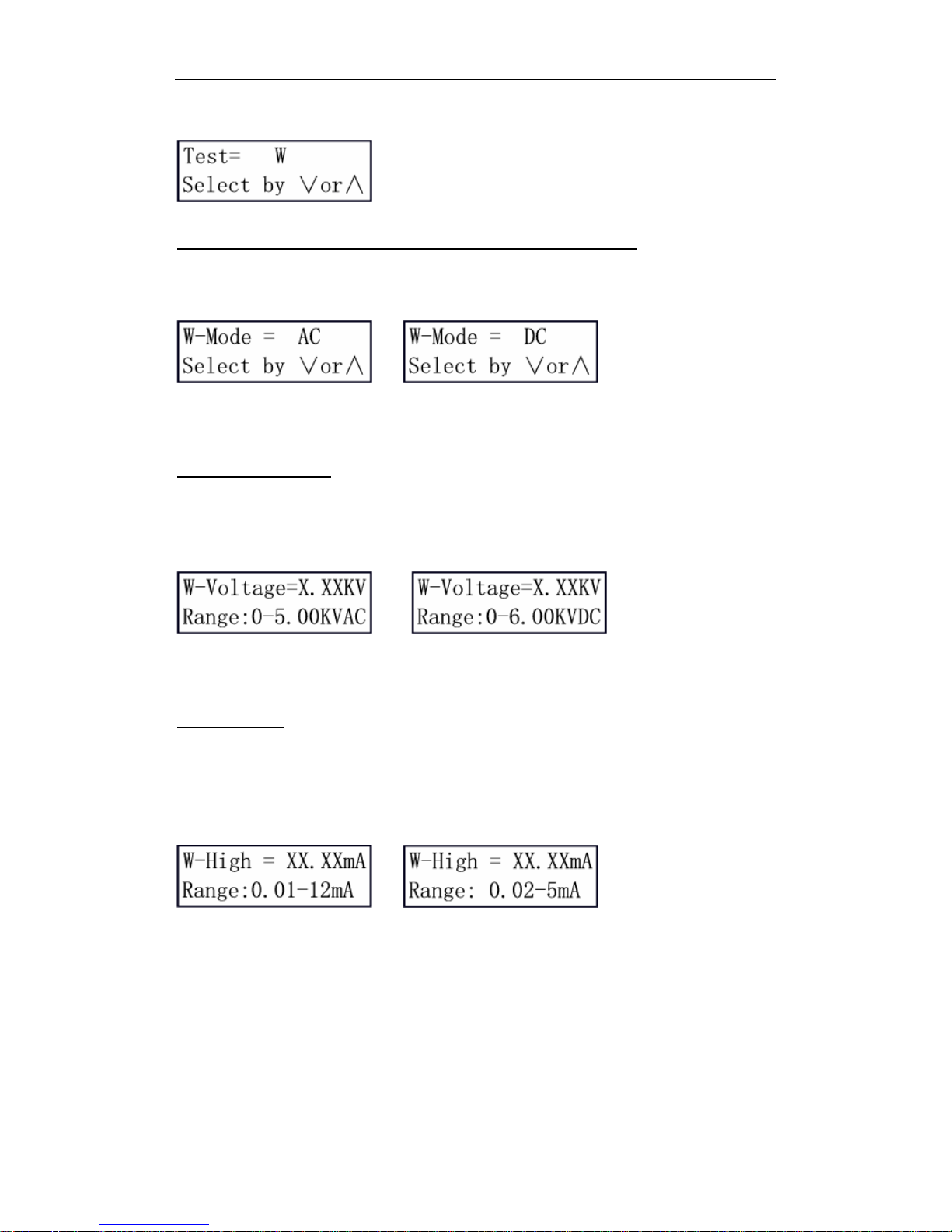
If test item is “withstanding voltage (W)”,LCD will display:
AC or DC withstanding voltage test select (TX5012DI/D)
When (W) is selected, press SET key,the procedure will enter AC or DC withstanding
voltage mode, and LCD will display:
or
Please use“∧”or“∨” to select the test mode.
Output voltage set
When AC or DC withstanding voltage test is selected, press SET key,procedure will
enter output voltage set mode, and LCD will display:
AC withstanding voltage test
DC withstanding voltage test
or
Please use“∧”or“∨” to input the output voltage, the unit is “kV”.
(HI-Limit) set
When output voltage of AC or DC withstanding voltage is set, press SET,the procedure
will enter leakage current hi-limit set mode of AC or DC withstanding voltage test,LCD
will display:
AC withstanding voltage test
DC withstanding voltage test
or
Please use “∧”or“∨” to input the hi-limit value, and the unit is “mA”。
Page 19
TX5012 Series Operation Manual Ver1.0
◇19
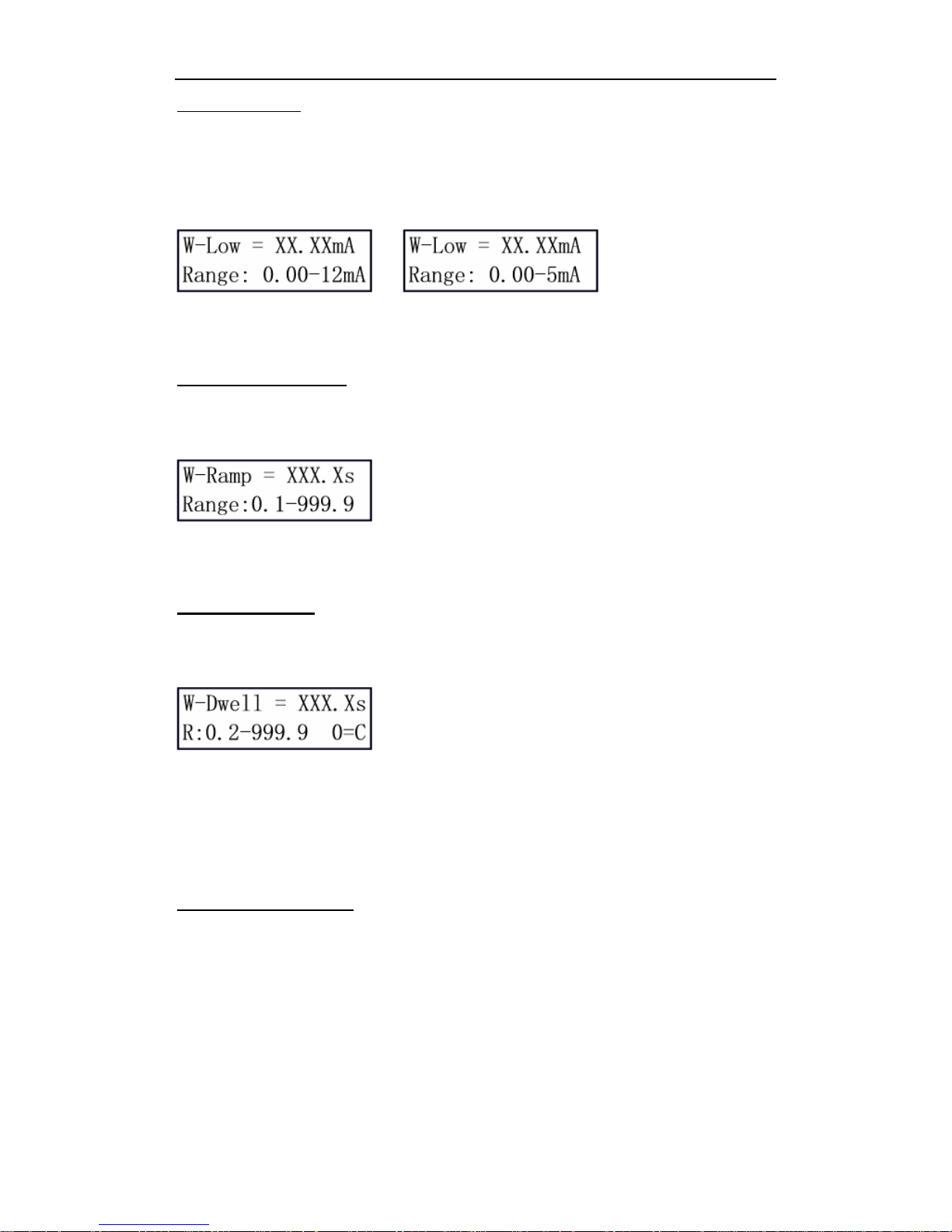
(LO-Limit) set
When leakage current hi-limit of AC or DC withstanding voltage test is set, press SET,
the procedure will enter low-limit set mode of AC or DC withstanding voltage test,LCD
will display:
AC withstanding voltage test
DC withstanding voltage test
or
Please use“∧”or“∨” to input the low-limit value, the unit is “mA”.
(Ramp UP) time set
When leakage current low-limit set is finished, press SET key,the procedure will enter
ramp up time set mode,LCD will display:
Please use “∧”or“∨” to input ramp up time value, and the unit is “s”.
(Dwell) time set
When ramp up time is set, press SET,the procedure will enter dwell time set mode, and
LCD will display
:
Please use “∧”or“∨” to input dwell time value, and the unit is “s”.
When test time is set as “0”,the set won’t stop unless the test is fail or stopped by
operator. Time counter will continue to Max.limit value then back to “0” for counting from
beginning, it won’t stop.
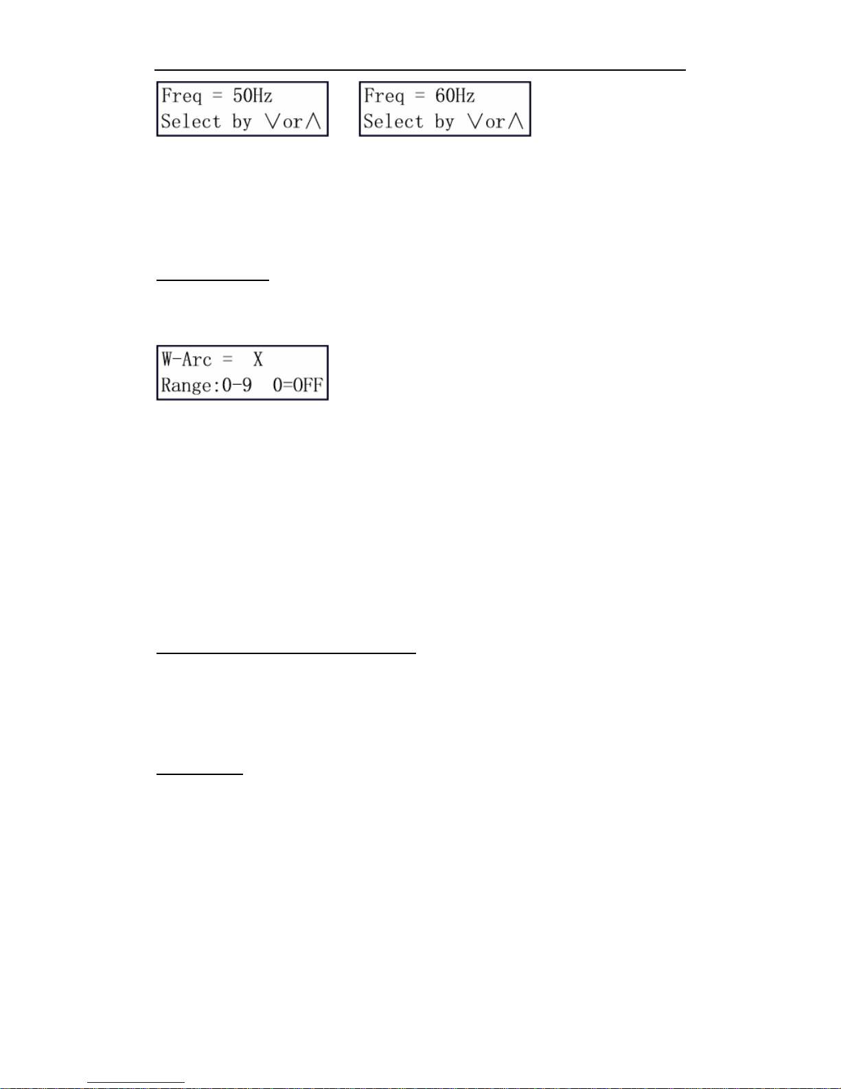
Output frequency set
When dwell time is set, press SET,the procedure will enter output frequency mode, and
LCD will display:
Page 20
TX5012 Series Operation Manual Ver1.0
◇20
or
Note:There is no such function in DC withstanding voltage test,the procedure will
ignore this set automatically to enter “Arc Sense” set.
Please use “∧”or “∨”to select frequency to be“50”or“60”Hz.
(Arc Sense) set
When output frequency is set, press SET,the procedure will enter arc sense set mode,
and LCD will display:
Please use “∧” or “∨” to input the arc sense value,arc sense is 1-9,there are 9
sections for setting,9 is the highest sense,but “0” is no detecting on Device Under Test.
Note:when the range of X is 1—9,and its arc peak value is: 20mA、18mA、16mA、
14mA、12mA、10mA、7.7mA、5.5mA、2.8mA,the default value is 5.
This is the last step of withstanding voltage test parameter set,you can press SET key to
the first parameter set,and check if there is some error in parameter,or press“EXIT”
to exit parameter set mode but to enter under test mode.
Insulation resistance parameter set
Insulation resistance parameter is also set by using SET key,press once to enter next
parameter item,and its sequence is (Memory) set, test item, output voltage set,
insulation resistance hi-limit set, insulation resistance low-limit set, delay time judge
time set.
Memory set
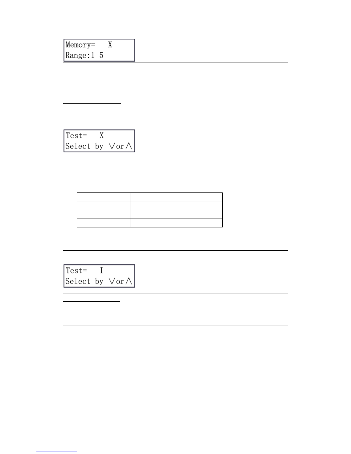
Press SET,the procedure will enter memory set mode automatically:
Page 21
TX5012 Series Operation Manual Ver1.0
21
Please use “∧”or“∨”to input the number in “Memory” to parameter setting procedure,
there are totally 5 group s.
Test item selection
When memory is set, press SET,the pr ocedure wi ll enter “Test item” mode,the LCD will
display:
Please use “∧” or “∨” to select the test i tem,there are withstanding voltage test(W),
Insulation resistance test (I), withstanding voltage and insulation resistance connection
test (W-I) and insulation resistance and withstanding voltage connection test (I-W) for
selecting.
Model Available test item
TX5012DI
W、I、W-I、I-W
TX5012D
W
TX5012
W
The sequence is (W), (I), (W-I),(I-W),when some model has no test item, the procedure
will ignore this item to next t est item. In this section, use item (W) to introduce continually.
If test item is selected as (I),LCD will display:
Output voltage set
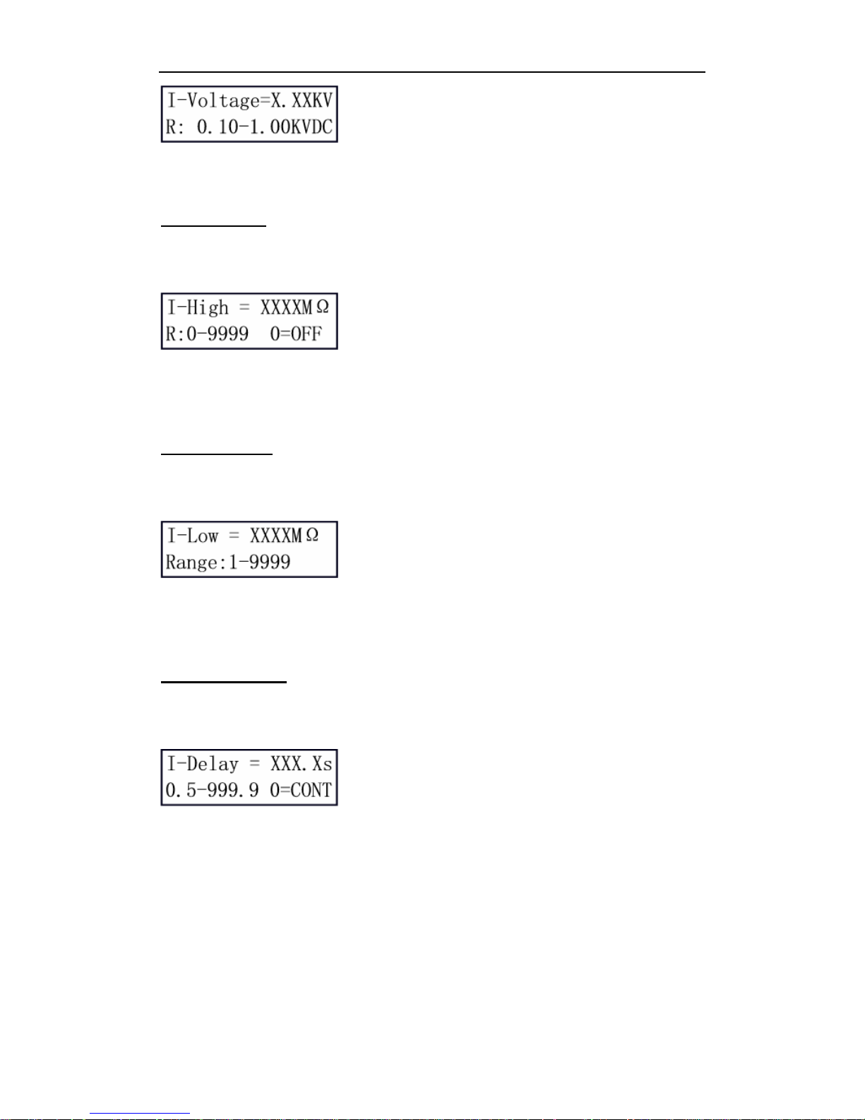
When test item is selected as insulation resistance, press SET key,the procedure will
enter output voltage set m ode, and the LCD will display:
Page 22
TX5012 Series Operation Manual Ver1.0
◇22
Please use “∧” or “∨” to input the output voltage,the unit is “kV”.
(HI-Limit) set
When output voltage of IR is set, press SET key,the procedure will enter hi-limit set
mode of insulation resistance, LCD will display:
Please use“∧” or “∨” to input high limit value of insulation resistance, and the unit is
“MΩ” ,if the high limit value is set as “0” ,which means no high limit judge.
(LO-Limit) set
When the high limit of insulation resistance is set, press SET,the procedure will enter
low limit set mode, and LCD will display:
Please use“∧” or “∨” to input the low limit value of insulation resistance,and the unit is
“MΩ”.
(Delay) time set
When low limit of insulation resistance is set, press SET,the procedure will enter delay
time judge set mode, LCD will display
:
Please use “∧”or“∨” to input delay time judge value,the unit is “s” ,When test time is
set as “0”,the set won’t stop unless the test is fail or stopped by operator. Time
counter will continue to Max.limit value then back to “0” for counting from beginning, it
Page 23
TX5012 Series Operation Manual Ver1.0
◇23
won’t stop.
This is the last step of insulation resistance test parameter set,you can press SET key to
the first parameter set,and check if there is some error in parameter,or press“EXIT” to
exit parameter set mode but to enter under test mode.
Withstanding voltage and insulation resistance connection (W-I) test
parameter set (TX5012)
The main function is that perform withstanding voltage test on DUTthen after that,
perform insulation resistance test automatically.
Memory set
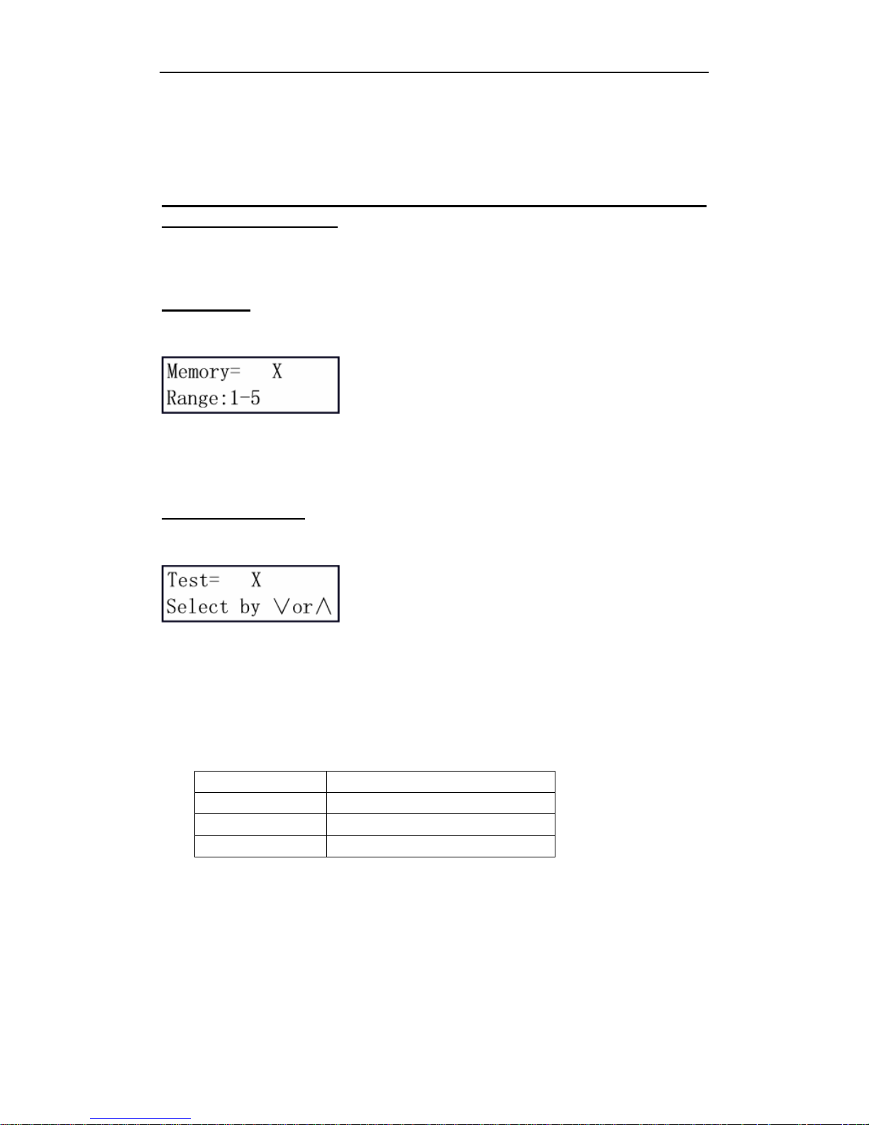
Press SET,the procedure will enter memory set mode automatically:
Please use “∧”or“∨”to input the number in “Memory” to parameter setting procedure,
there are totally 5 groups.
Test item selection
When memory is set, press SET,the procedure will enter “Test item” mode,the LCD will
display
Please use “∧” or “∨” to select the test item,there are withstanding voltage test(W),
Insulation resistance test (I), withstanding voltage and insulation resistance connection
test (W-I) and insulation resistance and withstanding voltage connection test (I-W) for
selecting.:
Model Available test item
TX5012 DI
W、I、W-I、I-W
TX5012D W
TX5012 W
The sequence is (W), (I), (W-I),(I-W),when some model has no test item, the procedure
Page 24
TX5012 Series Operation Manual Ver1.0
◇24
will ignore this item to next test item. In this section, use item (W-I) to introduce
continually.
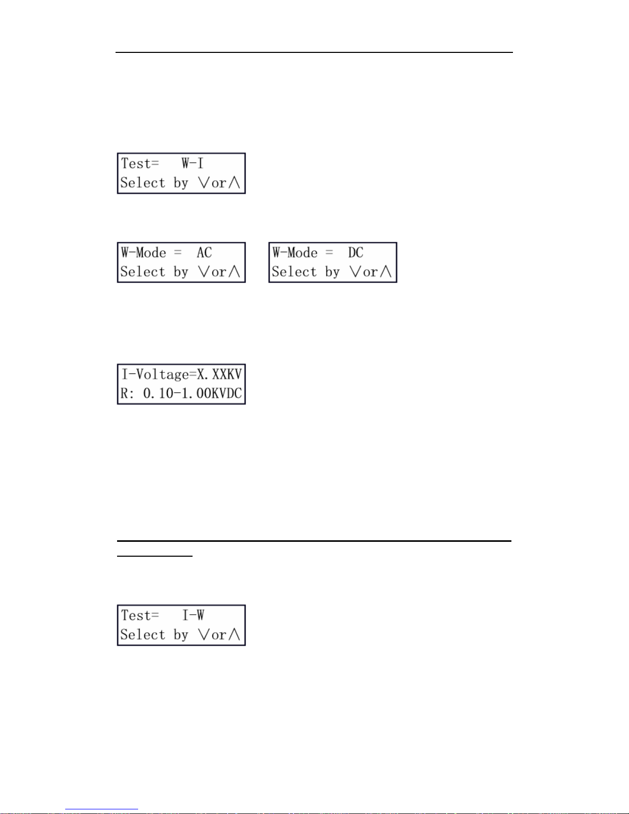
If test item is selected as “withstanding voltage and insulation resistance connection test
(W-I)”,LCD will display:
Press SET,procedure will enter the voltage set of “withstanding test”,LCD will display:
or
After entering withstanding voltage test parameter set mode,please enter test parameter
set according to “withstanding voltage test parameter set procedure. Then procedure
will enter insulation resistance parameter set automatically, LCD will display:
After entering insulation resistance test parameter set mode,please enter test parameter
set according to “insulation resistance test parameter set procedure”.
After last step is over, you can press SET key to the first parameter set,and check if
there is some error in parameter,or press“EXIT” to exit parameter set mode but to enter
under test mode.
Insulation resistance and withstanding voltage connection (I-W) test
parameter set
If test item is selected as “insulation resistance and withstanding voltage connection
(I-W)” test,LCD will display:
Page 25
TX5012 Series Operation Manual Ver1.0
◇25
The set procedure is the same as withstanding voltage and insulation resistance
connection test.
4.2 Displayed information
The following information will be displayed in the process of testing.
Withstanding voltage test:
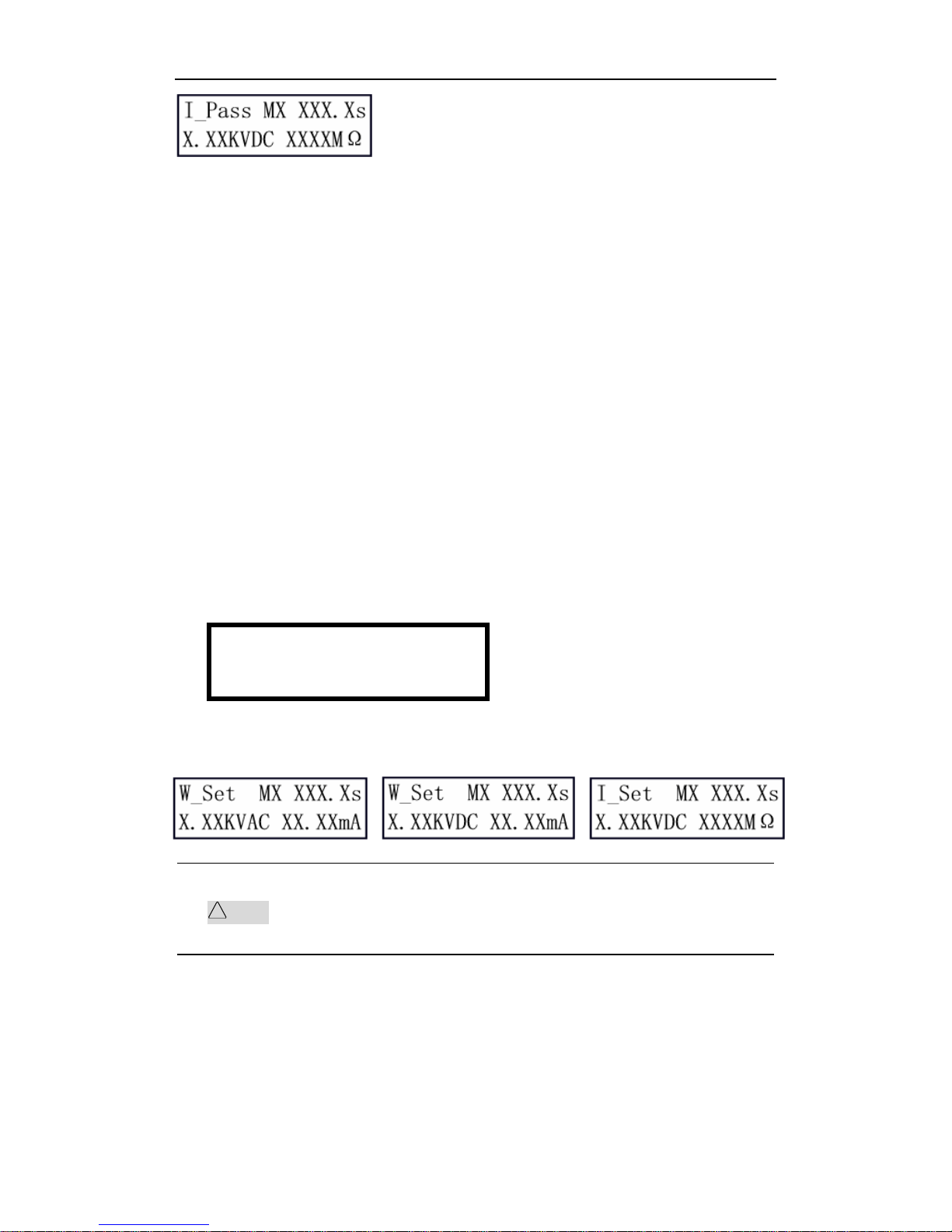
The display information of AC and DC withstanding voltage test is almost the same.
Under test and parameter set mode
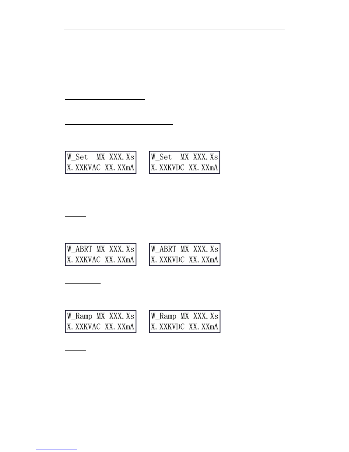
The following information means the instrument is in the under test and parameter set
mode
:
or
If press “TEST”,the instrument starts to test, if press “SET”,the instrument will enter
parameter set mode.
(Abort)
If AC or DC withstanding voltage test is in the process, and press “RESET” or use
remote control device to stop testing,LCD will display
:
or
(Ramp Up)
When AC or DC withstanding voltage is performed in ramp up time, the test result will be
updated, LCD will display:
or
(Dwell)
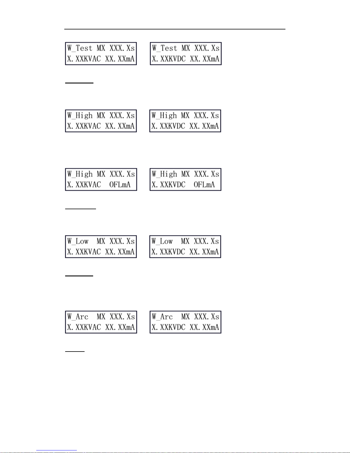
In AC or DC withstanding voltage test, test result will be updated, and LCD will display:
Page 26
TX5012 Series Operation Manual Ver1.0
◇26
or
(HI-Limit)
If the leakage current amount of DUT is over high limit value,the procedure will judge
test failure,if the leakage current value is within the range, LCD will display:
or
If the leakage current amount of DUT is over high limit value,the procedure will judge
test failure,if the leakage current value is over the range, LCD will display:
or
(LO-Limit)
If the leakage current amount of DUT is lower than low limit value,the procedure will
judge test failure, LCD will display:
or
(Arc Fail)
If leakage current amount of DUT is within the high limit, but that of arc is over the value
of arc current, and arc detection judge function is set as “ON”,it will cause failure,LCD
will display:
or
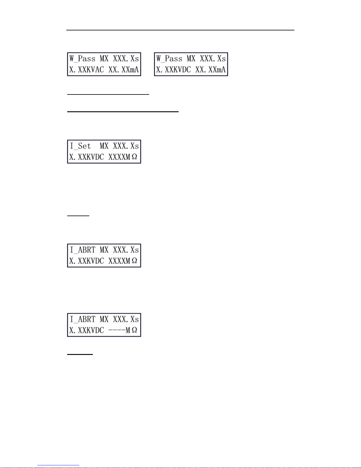
(Pass)
If DUT is tested normal, then it is considered as pass, LCD will display:
Page 27
TX5012 Series Operation Manual Ver1.0
◇27
or
Insulation resistance test:
Under test and parameter set mode
The following information means the instrument is in under test and parameter set
mode:
If press “TEST”, the instrument will start insulation resistance test,if press “SET”,the
instrument enters parameter set mode of insulation resistance timely, and parameter
can be set.
(Abort)
If insulation resistance test is in the process,and press “RESET” or use remote control
device to stop testing,LCD will display:
If insulation resistance test is in the process,and press “RESET” or use remote control
device to stop testing,but the stop time is before reading the complete test result, LCD
will display:
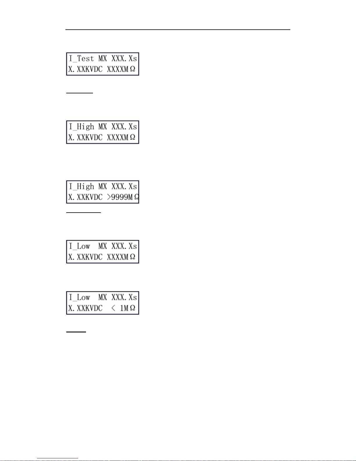
(Delay)
In insulation resistance test, the test result will be updated, LCD will display:
Page 28
TX5012 Series Operation Manual Ver1.0
◇28
HI-Limit)
If the insulation resistance value is over hi-limit,procedure will judge failure,if the
insulation resistance value is still within the test range, LCD will display:
If the insulation resistance value is over hi-limit, procedure will judge failure, if insulation
resistance value is over the test range, LDC will display:
(LO-Limit)
If the insulation resistance value is over low-limit, procedure will judge failure,if the
insulation resistance value is still within the test range, LCD will display:
If the insulation resistance value is over low-limit, procedure will judge failure,if the
insulation resistance value is over the test range, LCD will display
(Pass)
If DUT is tested normal, then it is considered as pass, LCD will display:
Page 29
TX5012 Series Operation Manual Ver1.0
◇29
4.3 Operation procedure and step
TX5012 series withstanding voltage tester is designed for production line or quality
inspection,its operation and setting is very convenient. Unreasonable setting and
operation will generate a warning,and back to former setting status meanwhile.
1. Before power plug is connected to commercial power,please turn off input “power
switch” ,and “voltage selection” is switched to right voltage-input position,check if
the standard of fuse is correct. Then connect the ground line to the “ground
terminal”.
2. Connect power line to the instrument and socket, please don’t connect test
cable to the output terminal firstly.
3. When the test cable of DUT or its test terminal is connected well, connect (Return)
to the return terminal of instrument, then connect high voltage test cable to the high
voltage terminal of instrument, and check if all test cables are connected well.
4. Start input “Power switch”,now the displayer shows:
Then the memory group and parameter data in the last test will be appeared,and
enter under test and parameter set mode, now displayer shows:
or or
!
Note:when there is “_” after “MX”,it means there is W-I or I –W test.
TX5012
VER:2.0
Page 30
TX5012 Series Operation Manual Ver1.0
◇30
5. If the test parameter needs resetting,please press “SET”. Detailed set method,
procedure and step are in “Test parameter set”
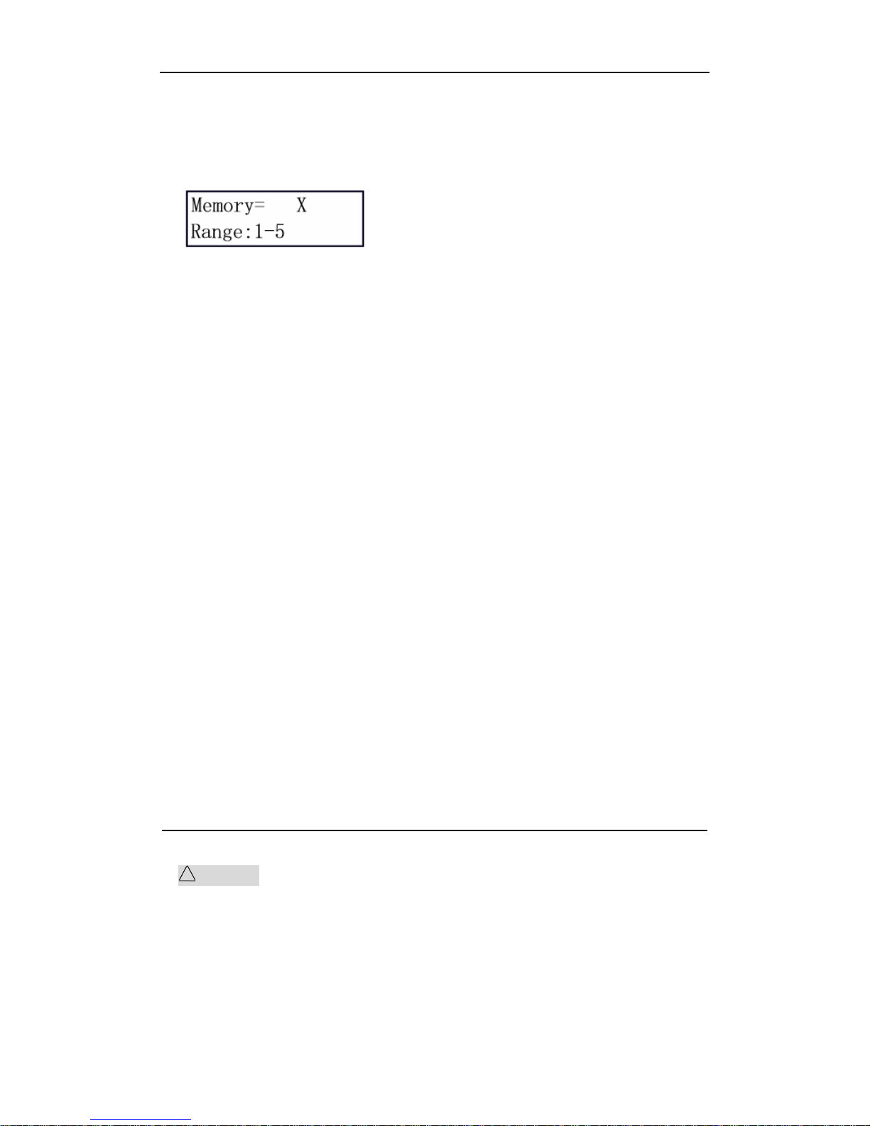
6. If you need to call the test parameter in memory group to test, please press
“SET”key,the procedure will enter set mode, and LCD displays:
Please use “∧”or“∨” to select the number of “procedure memory group”. Then
press “EXIT” to exit parameter set mode and return to under test and parameter set
mode,procedure will call the test parameter from memory group and wait for
testing,LCD will display the test parameter.
7. Press “TEST” to start testing,now the red “high voltage”symbol will shine,and time
counter starts counting meanwhile, now displayer displays the information of this
test.
After test is over, output will be off automatically,the green indicator in TEST will be
on,also there is a beeper,which means the DUT has passed test and
“PASS” and test value are displayed.
If the test is going on, press “TEST” again. If check the former set, then press
RESET,the procedure will clear the test result and display the former set.
8. If stop testing in the process of testing,please press RESET,the instrument stops
testing timely,displayer will keep the test value.
9. if the test is failed, the instrument will stop testing and displayer will display the
status and failed value,now red “RESET” indicator is on. Press RESET to turn off
warning and keep the test value.
10. If use external remote control device to operate hipot tester, please connect remote
controller to the remote input terminal. The function of TEST and RESET in remote
controller is the same as that in instrument.
!
Warning:Because the TEST and RESET switch in instrument and remote
Page 31

TX5012 Series Operation Manual Ver1.0
◇31
controller can be operated simultaneously, the remote controller has
to be kept well.
11. The PLC interface has “PASS、FAIL and PROCESSING” remote monitor signal
output,those signal can be connected to control center, remote monitor is accordant
with the signal action.
4.4 Keyboard lock
Press “SET”,then start input power switch, after power is setup, release the key, the
operation is finished.
Page 32
TX5012 Series Operation Manual Ver1.0
◇32
Chapter 5 Parameter instruction
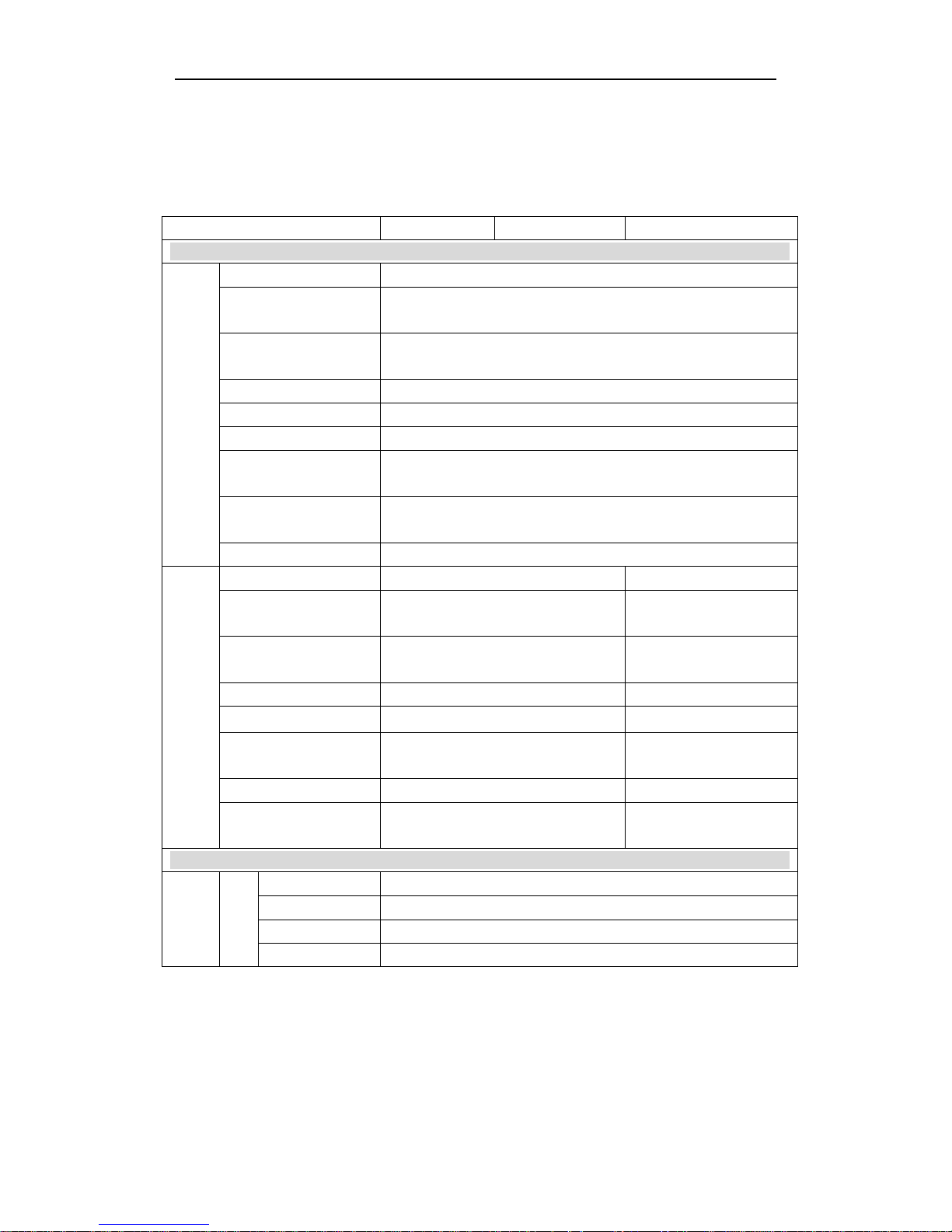
5.1 Withstanding voltage test parameter
Model TX5012DI TX5012D TX5012
Voltage output
Output voltage range 0 to 5.00kV
Output voltage
accuracy
±(2% set +5V)(no load)
Output voltage
resolution
10V
Max.rated power
60VA(5kV/12mA)
Max.rated current 12mA
Output waveform Sine waveform
Output waveform
distortion factor
≤±2%(load or pure resistance load)
Voltage adjusting
rate
±(1% set+5V)(rated power)
AC
ARC function
0,class 1- 9(0= OFF,class 9 is the highest sensitivity)
Output voltage range 0 -6.00kV ————
Output voltage
accuracy
±(2% set +5V) ————
Output voltage
resolution
10V ————
Max.rated power
30VA(6kV/5mA)
————
Max.rated current 5mA ————
Max.rated load
waveform
≤5%(6kV/5mA)
————
Discharge function
Fast discharge(≤200mSec)
————
DC
ARC function
0,class 1- 9(0= OFF,class 9 is
the highest sensitivity)
————
Test display
Test range 0.00kV to 6.00kV
Accuracy
±(2% set +1V)
Resolution 0.01kV
voltage
meter
Digit
Displayed RMS value
Page 33
TX5012 Series Operation Manual Ver1.0
◇33
value
AC 0.10mA -12.00mA
DC
Test range
0.02mA-5.00mA ————
Current
meter
Test accuracy ±(2% set+2 digits)
Parameter set
AC 0.10mA -12.00mA
DC
High limit
0.02mA - 5.00mA ————
AC 0.00mA -12.00mA
Judge
function
DC
Low limit
0.00mA-5.00mA ————
Rise time 0.1s - 999.9s
Tes t t i m e
0,0.2s - 999.9s(0means continue test)
Time
func
Time accuracy
±(0.1%set value +0.05s)
Storage
5 groups of test,4kinds of test mode
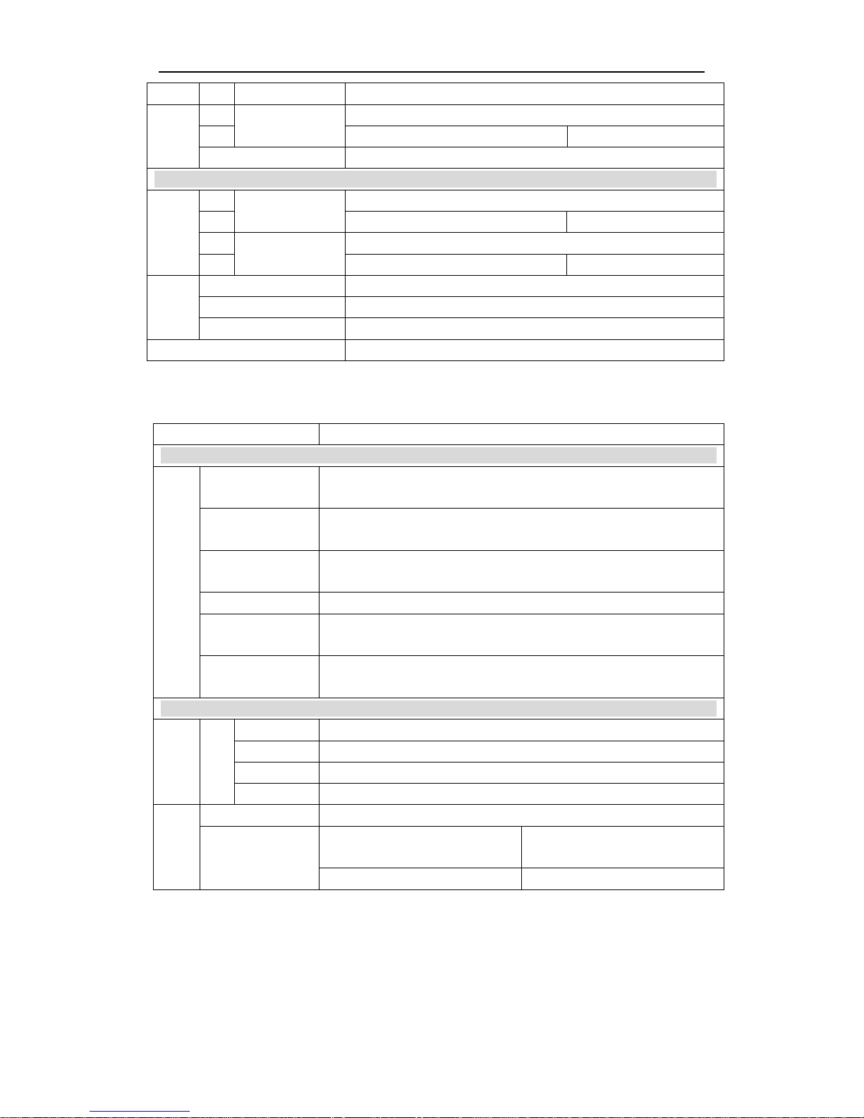
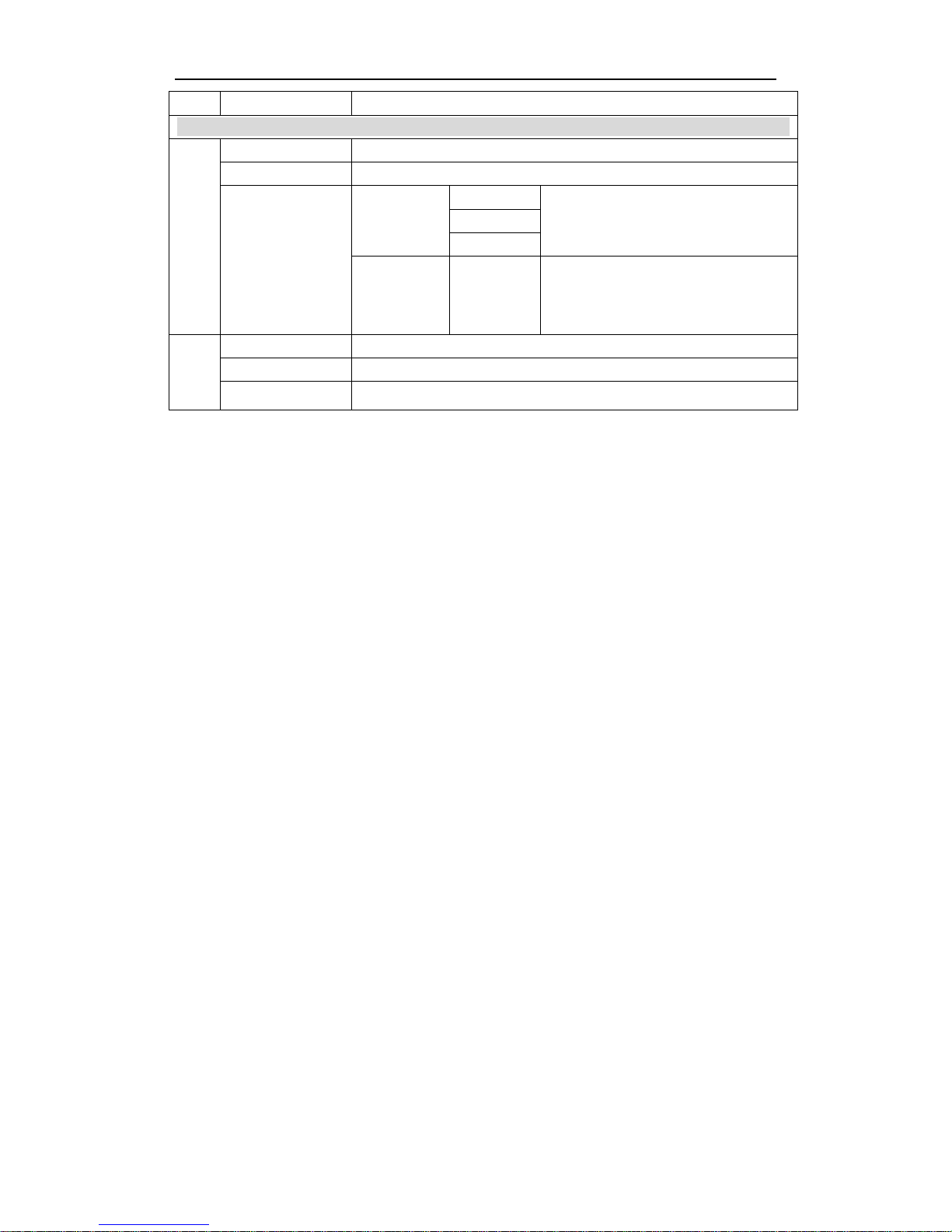
5.2 Insulation resistance parameter
Model TX5012DI
Voltage output
Output voltage
range
0.10kV-1.00kV
Output voltage
accuracy
±(2% set+2V)
Output voltage
resolution
0.01kV
Max.rated power
1VA(0.10kV/1mA)
Max.rated
current
1mA
IR
Discharge
function
Fast discharge(≤200mSec)
Voltage display
Test range 0.10kV – 1.00kV
Accuracy ±(2% set+2V)
Resolution 1V
Voltage
meter
Digit
Value RMS value
Test range 1MΩ- 9999MΩ
1MΩ- 1000MΩ
±(5% set+2digits) >500V
±(10% set+2digits) <500V
Resistance
meter
Test accuracy
1000MΩ- 9999MΩ
±(10% set+2digits) >500V
Page 34
TX5012 Series Operation Manual Ver1.0
◇34
Test time 100ms
Parameter set
Hi-limit set
0,1MΩ- 9999MΩ(0 means OFF)
Low-limit set 1MΩ- 9999MΩ
0.001 MΩ
0.01 MΩ
1 -1000 MΩ
0.1 MΩ
±(5% set+2 digits) >500V
±(10% set+2 digits) <500V
Judge function
Judge accuracy
1000 MΩ-
9999 MΩ
1 MΩ
±(10% set+2 digits) >500V
Rise time 0.1s to 999.9s
Wait time
0,2s -999.9s
Time
function
Time accuracy
±(0.1% set value + 0.05s)
Page 35
TX5012 Series Operation Manual Ver1.0
◇35
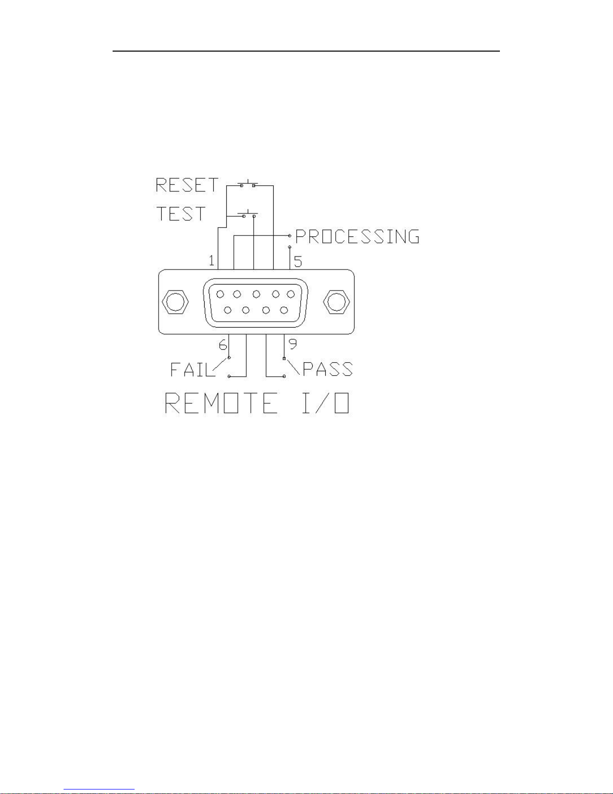
5.3 Interface instruction
Standard PLC remote control interface:
There is remote monitor and remote control connection terminal on the rear panel,which
can connect the working status to the monitor center, also can be connected with remote
controller. This terminal is a standard 9PIND board,which contains monitoring signal
output:PROCESSING,PASS,FAIL and 2 remote input signal: TEST,RESET.
1. Remote control output signal connection and instruction
TX5012 series Hipot tester provides no-power (N.O)point to the signal below.
The capacitance of the connection point is AC 250V 1.0Amp,also these points
have no positive and negative limitation,and each signal has a dependant
connection line,but no(COMMON). The connection line of output signal is as
below:
z PROCESSING signal:output signal is connected between PIN2 and PIN5.
z PASS signal:output signal is connected between PIN8 and PIN9.
z FAIL signal:output signal is connected between PIN6 and PIN7.
2. Remote control output signal connection instruction
TX5012 series Hipot tester has remote control connection point,the external
remote control device controls TEST function. These connection points
Page 36

TX5012 Series Operation Manual Ver1.0
◇36
provide the power with controlling function, and MOMENTARY switch should
be the controller. Please pay attention,don’t connect any other power,if
so, the internal circuit will be damaged. PIN5 is(COMMON)ground line for
remote controlling operation,the connection is listed as below:
z RESET:control switch is between PIN1 and PIN4.
z TEST:control switch is between PIN1 and PIN3.
Note:The operation of remote controller and hipot tester can be performed
simultaneously,so the controller should be kept well .
Page 37
◇37
Chapter 6 Calibration and daily
maintenance
6.1 Clean
The front and rear panel should be cleaned by neutral cleanser.
! Warning:Before cleaning, power should be off and power line should be
removed.
6.2 Check
! Warning:The damage of cable may cause electrical shock or fire, the instrument
has to be stopped under this situation.
6.3 Maintenance
! Warning : Only the technician can open the instrument to replace the
components. If you need to replace, please contact us.
■ High voltage relay
We suggest the high voltage relay should be replaced after million tests.
Page 38
TX5012 Series Operation Manual Ver1.0
◇38
6.3.1 Calibration
We suggest instrument should be calibrated per year, and the accuracy should be
within 0.5%.
! Warning:The instrument generates high voltage of AC 5kV and DC 6kV, so
calibration is very dangerous, if you need calibration, please contact us.
Instrument and device for calibration:
The following instruments and devices can be used for calibration,please be sure that
the accuracy of the instruments and devices are within 0.5%.
1. High voltage meter:test range is above 0-6000V AC
2. Current meter:range is above 0-15mA AC
3. Current meter:range is above 0-5mA DC
4. Load:resistance is about 1MΩ/4W
Calibration step:
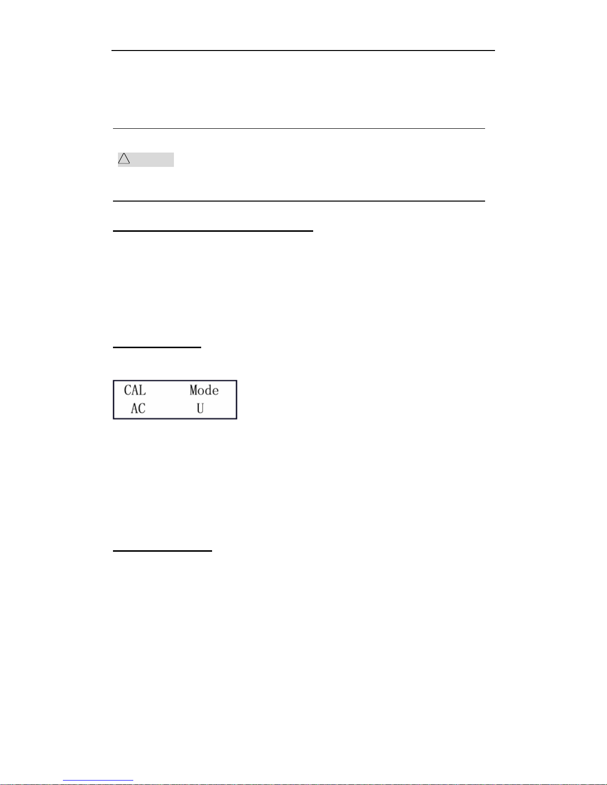
Press “”UP∧ and EXIT,then start input power switch,LCD will display:
Now the instrument is in calibration procedure,please release key.
Use “ ”∧ or“ ”∨ to select the tested item,there are 4 items for calibration, which are
AC voltage(AC U), AC Current (AC I), DC voltage(DC U), DC current(DC I).
Note:The hipot can only select one item to calibrate.
Voltage calibration
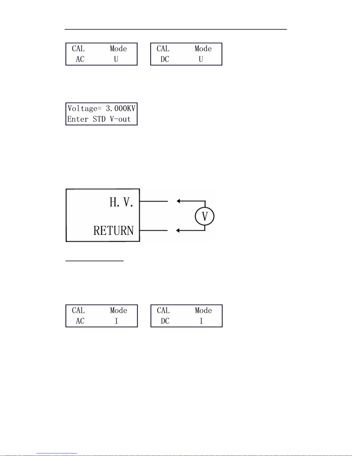
Connect “H.V.” and “RETURN” to a standard voltage meter that can test 6000V
AC/DC.
Press “ ”∧ or “ ”∨ to enter(AC U)or(DC U)calibration item,now LCD displays:
Page 39
TX5012 Series Operation Manual Ver1.0
◇39
AC voltage DC voltage
or
Then press TEST,the calibration procedure outputs 3000V AC or DC voltage,after
rise time is over, it displays:
Use “ ”∧ or “ ”∨ to input standard voltage to calibration procedure.
Please make sure the number is correct , then press SET to input calibration
parameter,if you need to stop changing calibration parameter,then press EXIT or
RESET,the instrument will return to calibration mode,and wait for the next calibration.
Please refer to the connection diagram below:
Current calibration
Please connect standard current meter and 1MΩ resistor serially,then connect to
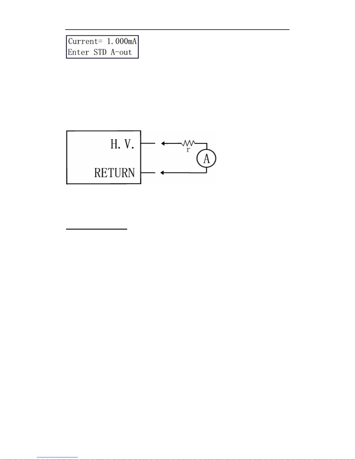
“H.V.” and “RETURN”., next use “ ”∧ or “ ”∨ to select (AC I)or(DC I)calibration item,
LCD displays:
AC current DC current
or
Then press TEST,now the calibration procedure outputs about 1000V AC or DC
voltage,after rise time is over, it displays:
Page 40
TX5012 Series Operation Manual Ver1.0
◇40
Use “ ”∧ or “ ”∨ to input standard current value to calibration procedure.
Please make sure the number is correct , then press SET to input calibration
parameter,if you need to stop changing calibration parameter,then press EXIT or
RESET,the instrument will return to calibration mode,and wait for the next calibration.
Please refer to the connection diagram below:
:
Note:please connect current meter to the terminal near RETURN,to avoid the
current value is not accurate or current meter is damaged.
Calibration finished
After calibrating DC voltage and current,procedure finishes the calibration to
insulation resistance automatically. So, no need to calibrate insulation
resistance.
After calibrated parameter is input, the power must be turned off, then start the
instrument, otherwise, it can’t enter the under test mode. When power is off, the
procedure will save the calibrated parameter to storage.
 Loading...