

Page 1
Page 2

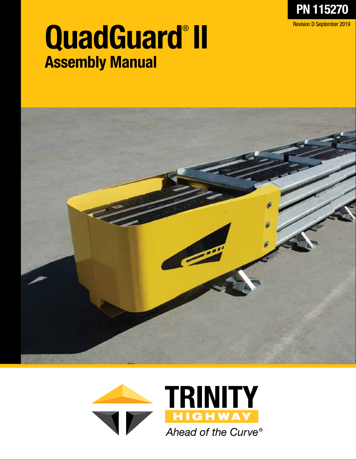
QuadGuard® II
The QuadGuard® II has been tested pursuant to National Cooperative Highway Research Program
(“NCHRP”) Report 350 specifications. The QuadGuard
reimbursement on the National Highway System by the Federal Highway Administration (“FHWA”).
®
II has been deemed eligible for federal-aid
Assembly Manual
2525 N. Stemmons Freeway
Dallas, Texas 75207
Warning:
lessors, and lessees are RESPONSIBLE for the assembly, maintenance, and
repair of the QuadGuard
respect to the assembly, maintenance, and repair of the QuadGuard
system could result in serious injury or death.
The local highway authority, distributors, owners, contractors,
®
II. Failure to fulfill these RESPONSIBILITIES with
®
II
Important:
appropriate highway authority. In the event the specified system assembly,
maintenance, or repair would require a deviation from standard assembly
parameters, contact a Trinity Highway representative. This system has been
deemed eligible by the FHWA for use on the national highway system under strict
criteria utilized by that agency.
This manual must be available to the worker overseeing and/or assembling the product at
all times. For additional copies, contact Trinity Highway directly at (888) 323-6374 or visit
trinityhighway.com.
The instructions contained in this manual supersede all previous information and manuals. All
information, illustrations, and specifications in this manual are based on the latest QuadGuard
information available to Trinity Highway at the time of printing. We reserve the right to make
changes at any time. Please contact Trinity Highway to confirm that you are referring to the most
current instructions.
QuadGuard® is a registered trademark of Energy Absorption Systems, Inc.
© 2019 Trinity Highway Products, LLC
trinityhighway.com 1 Revision D September 2019
These instructions are for standard assembly specified by the
®
II
Part No. 115270
Page 3

Table of Contents
Customer Service Contacts .......................................................................................................... 3
Important Introductory Notes ........................................................................................................ 3
Safety Symbols ............................................................................................................................. 4
Safety Rules for Assembly ............................................................................................................ 4
Limitations and Warnings .............................................................................................................. 5
System Overview .......................................................................................................................... 6
Inspect Shipping...................................................................................................................... 6
System Components ............................................................................................................... 7
Foundation/Anchoring ................................................................................................................. 12
Recommended Tools .................................................................................................................. 13
Site Preparation/Foundation ....................................................................................................... 15
Trinity Highway Approved Adhesive Anchoring System ............................................................. 16
Vertical Assemblies ............................................................................................................... 16
Anchor Assembly Cautions ................................................................................................... 17
Horizontal Assemblies ........................................................................................................... 18
How to Determine Left/Right ................................................................................................. 20
Counting the Number of Bays ............................................................................................... 20
Parallel (Narrow) Systems .......................................................................................................... 22
Assemble Parallel (Narrow) ........................................................................................................ 23
Determine Backup and Transition Type ................................................................................ 23
Flared (Wide) Systems ............................................................................................................... 40
Assemble Flared (Wide) ............................................................................................................. 41
Determine Backup and Transition Type ................................................................................ 41
QuadGuard
Maintenance and Repair ............................................................................................................. 58
Inspection Frequency ............................................................................................................ 58
Visual Drive-By Inspection .................................................................................................... 58
Walk-Up Checklist ................................................................................................................. 58
Post-Impact Instructions ........................................................................................................ 59
Parts Ordering Procedure ........................................................................................................... 62
®
II Final Inspection Checklist ................................................................................... 57
trinityhighway.com 2 Revision D September 2019
Page 4
Customer Service Contacts
Trinity Highway is committed to the highest level of customer service. Feedback regarding the
QuadGuard
®
II, its assembly procedures, supporting documentation, and performance is always
welcome. Additional information can be obtained from the contact information below:
Trinity Highway
Telephone:
E-mail: [email protected]
Website: trinityhighway.com
(888) 323-6374 (USA)
+1 214 589-8140 (International)
Important Introductory Notes
The performance of the QuadGuard® II as designed, and approved for reimbursement by the
FHWA pursuant to its NCHRP Report 350 standard, is dependent upon the proper assembly,
deployment and future maintenance of the system. These instructions must be read in their
entirety and understood before assembling the QuadGuard
in conjunction with the assembly of QuadGuard
®
II and are for standard assemblies only as
specified by the applicable highway authority. If you need additional information, or have
questions about the QuadGuard
®
II, please contact the highway authority that has planned and
specified this assembly and, if needed, contact Trinity Highway Customer Service. This product
must be assembled in the location specified by the appropriate highway authority. If there are
deviations, alterations, or departures from the assembly instructions specified in this manual, the
device may not perform as tested.
®
II. These instructions are to be used
Important:
specified herein for the QuadGuard
DO NOT use any component part that has not been specifically
®
II during the assembly or repair (pp. 7 – 11 /
63 - 64).
This product has been specified for use by the appropriate highway authority and has been
provided to that user who has unique knowledge of how this system is to be assembled. No
person should be permitted to assemble, maintain, or repair this system that does not possess
the unique knowledge described herein. These instructions are intended for an individual
qualified to both read and accurately interpret them as written. These instructions are intended
only for an individual experienced and skilled in the assembly of highway products that are
specified and selected by the highway authority.
A manufacturer’s drawing package will be supplied by Trinity Highway upon request. Each
system will be supplied with a specific drawing package unique to that system. Such drawings
take precedence over information in this manual and shall be studied thoroughly by a qualified
individual who is skilled in interpreting them before the start of any product assembly.
trinityhighway.com 3 Revision D September 2019
Page 5
Safety Symbols
This section describes the safety symbols that appear in this manual. Read the manual for
complete safety, assembly, operating, maintenance, repair, and service information.
Symbol Meaning
Safety Alert Symbol:
Indicates Important, Caution, Warning, or Danger. Failure
to read and follow the Important, Caution, Warning, or Danger indicators could
result in serious injury or death to the workers and/or bystanders.
Warning:
Read safety instructions thoroughly and follow the assembly directions
and suggested safe practices before assembling, maintaining, or repairing the
QuadGuard
®
II. It is the responsibility of the installer to follow these warnings.
Failure to comply with these warnings could result in increased risk of serious injury
or death in the event of a vehicle impact with a system.
Important:
Please keep up-to-date instructions for later use and reference by
anyone involved in the assembly of the product.
Safety Rules for Assembly
* Important Safety Instructions *
This manual must be kept in a location where it is readily available to per sons who are skilled and
experienced in the assembly, maintenance, or repair of the QuadGuard
this manual are available from Trinity Highway by calling (888) 323-6374, or by email at
[email protected], or at trinityhighway.com. Please contact Trinity Highway if you have any
questions concerning the information in this manual or about the QuadGuard® II.
It is the responsibility of the installer to use appropriate safety precautions when operating power
equipment, mixing chemicals, and when moving heavy equipment or QuadGuard
Safety articles including but not necessarily limited to work gloves, eye protection, safety-toe
shoes, and back support should be used.
®
II. Additional copies of
®
II components.
Warning:
It is the responsibility of the installer to use all safety measures
incorporating appropriate traffic control devices specified by the highway authority.
These measures must be used to protect all personnel while at the assembly,
maintenance, or repair site.
Warning:
Failure to comply with these warnings could result in increased risk of
serious injury or death in the event of a vehicle impact with a system that has not
been accepted by the FHWA.
Warning:
Use only Trinity Highway parts on the QuadGuard® II for assembly,
maintenance, or repair. The use of component parts not specified herein is strictly
prohibited. The QuadGuard
tested, approved, and accepted for state use by the FHWA. A QuadGuard
®
II assembled with Trinity Highway parts has been
®
II using
parts other than those specified herein has not been tested, approved, or accepted
for state use by the FHWA. Failure to follow this warning could result in increased
risk of serious injury or death in the event of a vehicle impact.
trinityhighway.com 4 Revision D September 2019
Page 6
Limitations and Warnings
Trinity Highway contracts with FHWA approved testing facilities to perform crash tests, evaluate
test results, and submit results to the FHWA for review.
®
The QuadGuard
requirements and guidelines of NCHRP Report 350. NCHRP Report 350 tests are designed to
evaluate product performance involving a range of vehicles on roadways, from lightweight cars
(approx. 1800 lb. [820 kg]) to full size pickup trucks (approx. 4400 lb. [2000 kg]). A product can
be certified for multiple Test Levels. The QuadGuard
shown below:
Test Level 2: 43 mph [70 km/h]
Test Level 3: 62 mph [100 km/h]
These FHWA directed tests are not intended to represent the performance of systems
when impacted by every vehicle type or every impact condition existing on the roadway.
This system is tested only to the test matrix criteria of NCHRP Report 350 as approved by
FHWA.
Trinity Highway expressly disclaims any warranty or liability for injury or damage to persons or
property resulting from any impact, collision or harmful contact with products, other vehicles, or
nearby
hazards or objects by any vehicle, object or person, whether or not the products were
assembled in consultation with Trinity Highway or by third parties.
The QuadGuard
and federal guidelines. It is important for the highway authority specifying the use of a highway
product to select the most appropriate product configuration for its site specifications. The
customer should be careful to properly select, assemble, and maintain the product. Site lay out,
vehicle population type; speed, traffic direction, and visibility are important elements that require
evaluation in the selection of a highway product. For example, curbs could cause an untested
effect on an impacting vehicle.
II has been deemed eligible for reimbursement by FHWA as meeting the
®
II system is certified to the Test Level(s) as
®
II is intended to be assembled, delineated, and maintained within specific state
After an impact occurs, the debris from the impact should be removed from the area immediately
and the specified highway product should be evaluated and restored to its original specified
condition or replaced as the highway authority determines as soon as possible.
Warning: Do not assemble, maintain, or repair the QuadGuard
®
II until you have
read this manual thoroughly and completely understand it. Ensure that all Danger,
Warning, Caution, and Important statements within the manual are completely
followed. Please call Trinity Highway at (888) 323-6374 if you do not understand
these instructions.
Warning: Ensure that all of the QuadGuard
Important statements within the QuadGuard
®
II Danger, Warning, Caution, and
®
II manual are completely followed.
Failure to follow this warning could result in serious injury or death in the event of
a collision.
trinityhighway.com 5 Revision D September 2019
Page 7
System Overview
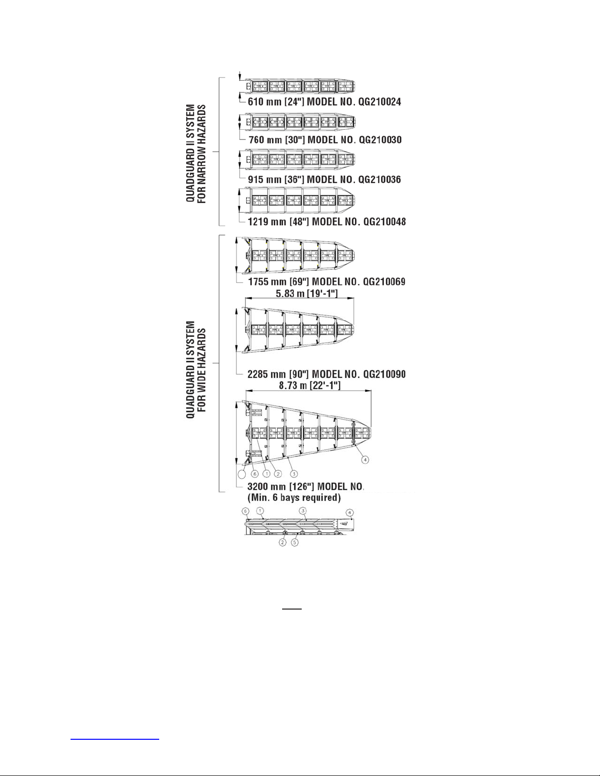
The QuadGuard® II is a re-directive, non-gating crash cushion for roadside obstacles ranging in
width from 24" to 126" (610 mm to 3200 mm). It consists of energy-absorbing cartridges
surrounded by a framework of Quad-Beam Panels.
Important:
reuse of any part of the system is appropriate or acceptable following an
impact. It is the sole responsibility of the project engineer and/or the local
highway authority and its engineers to make that determination. It is critical
that you inspect this product after assembly is complete to make certain that
the instructions provided in this manual have been strictly followed.
®
The QuadGuard
both lighter cars and heavier, high center-of-gravity vehicles. Its modular design allows the system
length to be tailored to the design speed of a site.
II utilizes two types of cartridges in a staged configuration designed to address
Trinity Highway makes no recommendation whether use or
Impact Performance
The 5 Bay QuadGuard® II has successfully passed the requirements outlined in NCHRP Report
350, Test Level 3 tests with both the light car and pickup at speeds of up to 62 mph [1 00 km/h] at
angles up to 20 degrees.
During head-on impact testing, within NCHRP Report 350 criteria, the QuadGuard® II is designed
to telescope rearward to absorb the energy of impact. When impacted from the side, within the
applicable NCHRP Report 350 criteria, it is designed to redirect the vehicle back toward its original
travel path and away from the roadside obstacle.
Warning:
Do not modify the QuadGuard® II in any way.
Warning:
authority and its engineer to ensure that the QuadGuard
meet all federal, state, specifying agency, and local specifications.
Warning:
authority and its engineer to ensure delineation on the assembly meets all
appropriate Manual on Uniform Traffic Control Devices (“MUTCD”) and local
standards.
It is the responsibility of the project engineer and / or local highway
It is the responsibility of the project engineer and / or local highway
®
II and delineation used
Inspect Shipping
Before deploying the QuadGuard® II, check the received parts against the shipping list supplied
with the system. Make sure all parts have been received.
Important:
QuadGuard
should take precedence over these general instructions.
trinityhighway.com 6 Revision D September 2019
The Manufacturer’s Drawing Package supplied with the
®
II must be used with these instructions for proper assembly and
Page 8
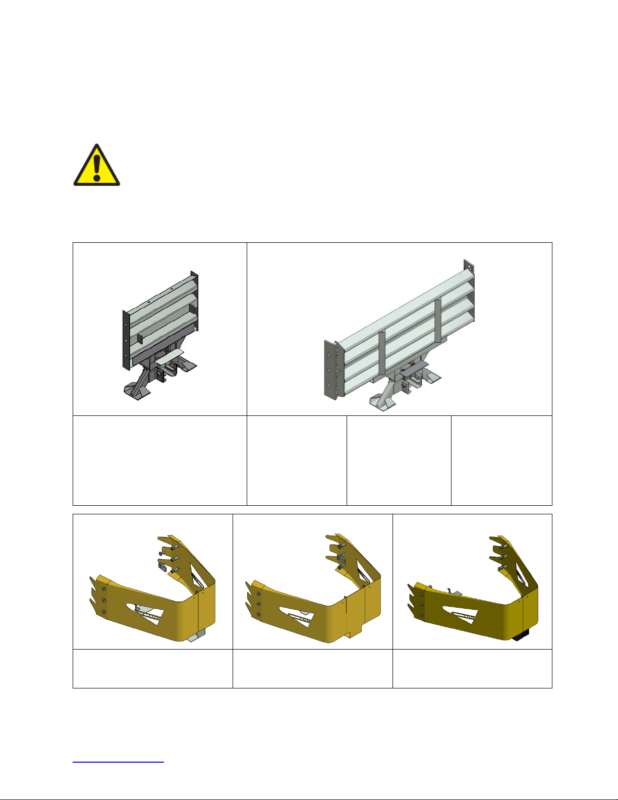
System Components
Below is a list of system components to be used in the repair of your particular QuadGuard® II
configuration. Please call Trinity Highway customer support if you have any system questions
(p. 3).
Warning:
QuadGuard
Use only Trinity Highway parts that are specified herein for the
®
II for assembling, maintaining, or repairing the QuadGuard® II. Do
not utilize or otherwise comingle parts from other systems even if those
systems are other Trinity Highway systems. Such configurations have not been
tested, nor have they been deemed eligible for use. Assembly, maintenance, or
repairs using unspecified parts or accessories is strictly prohibited.
Note:
Components are not shown to scale.
Narrow Diaphragm Assemblies * Wide Diaphragm Assemblies *
607173 - 26.48”
625650 - 24”
625651 - 30”
625652 - 36”
606810 - 48”
607174 – 29.65”
607175 – 32.78”
607176 – 35.93”
607177 – 39.08”
607145 – 42.23”
607146 – 45.38”
607148 – 48.53”
607149 – 50.11”
607150 – 51.68”
607151 – 54.83”
607152 – 57.98”
607156 – 59.56”
607157 – 61.13”
607158 – 64.28”
607159 – 68.06”
607160 – 70.58”
607162 – 73.73”
607163 – 76.88”
607164 – 80.04”
Nose, Narrow Assembly * Nose, Narrow Assembly 48” * Nose, Wide Assembly *
611580 - Galvanized
611581 - Yellow
611579 - Black
611577 - Galvanized
611578 – Yellow
611576 - Black
611583 – Galvanized
611584 – Yellow
611582 - Black
* Assemblies include multiple parts.
trinityhighway.com 7 Revision D September 2019
Page 9
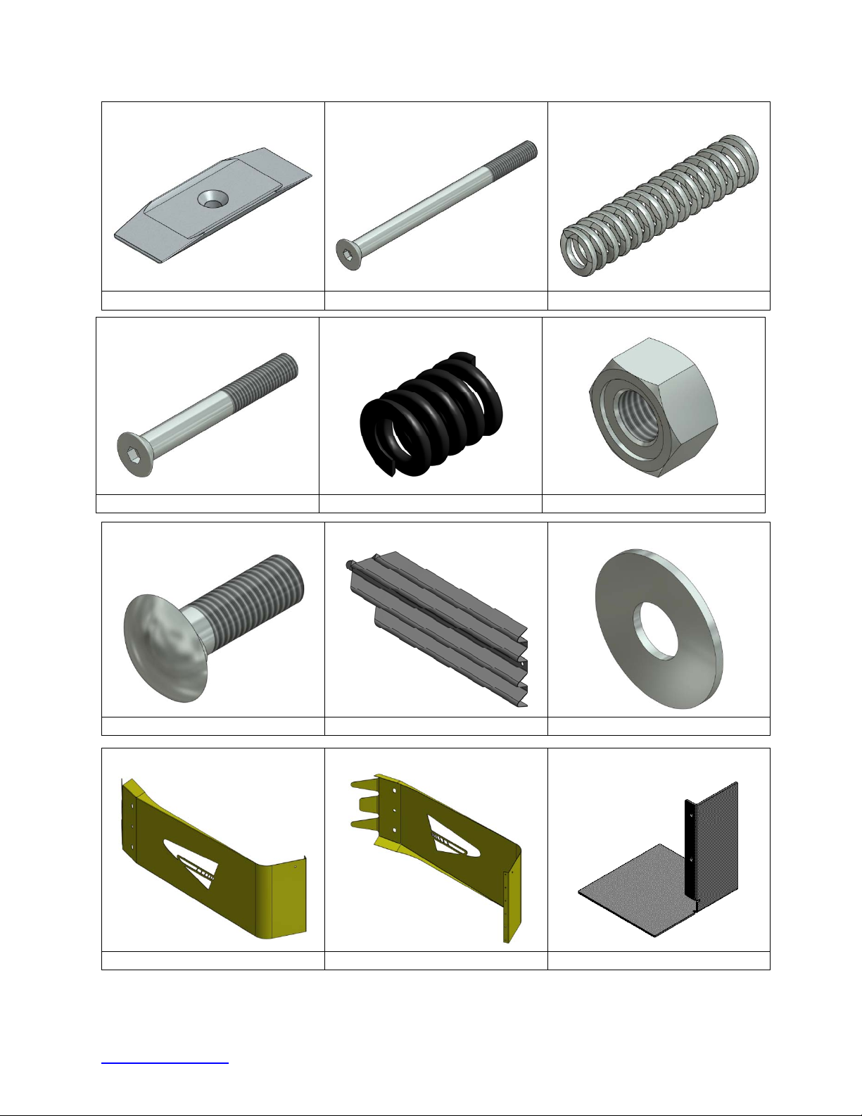
Mushroom Washer Flat Screw 5/8X8 1/2" Wide Die Spring, 6”, Wide
617045 116879 117458
Flat Screw 5/8X5”,G8, Narrow Die Spring, 1 1/2”, Narrow Rail Nut, Hex, 5/8”
116878 117459 003340
Rail Bolt, 5/8X2” Panel, Fender Assembly, QG Washer, Flat, 5/8” X 1 3/4"
003400 608236 003300
Nose, L, Wide, W/Logo Nose, R, Wide, W/Logo Bracket, Cart Support, Nose
611672 611683 605430
* Parts in red are included in assemblies.
trinityhighway.com 8 Revision D September 2019
Page 10
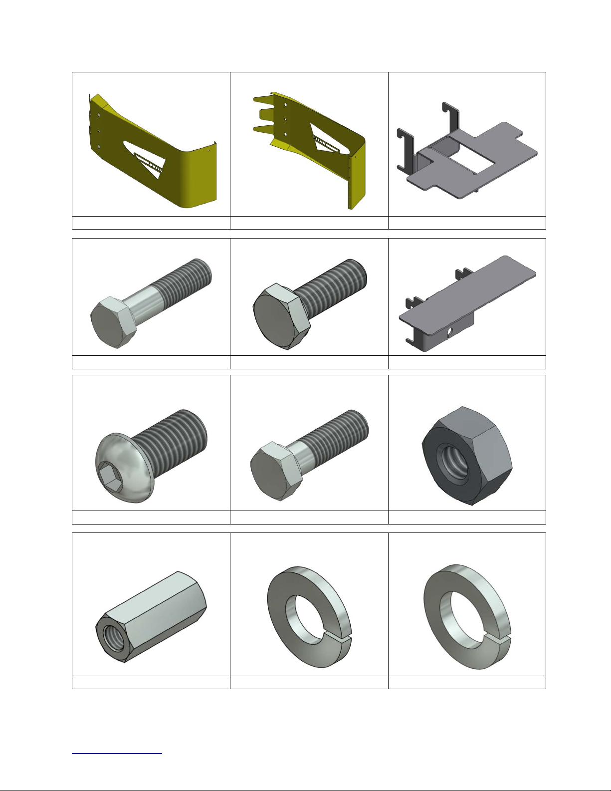
Nose, L, Narrow, W/Logo Nose, R, Narrow, W/Logo Bracket, Cart, Nose
611669 611680 605420
Bolt, Hex, 5/8” X 2 1/2", G5 Bolt, Hex, 1/4" X 3/4", G5 Bracket, Cartridge Support
118232 113518 605446
Bolt, Bt, 5/8” X 1 1/4", Hex
Bolt, Hex, 5/8” X 2”, G5 Nut, Hex, 1/4"
Socket
113404 118570 115946
Nut, Hex, Coupling, 5/8” 11” X
Washer, Lock, 1/4" Washer, Lock, 5/8”
2 1/8”
115986 118085 118100
* Parts in red are included in assemblies.
trinityhighway.com 9 Revision D September 2019
Page 11
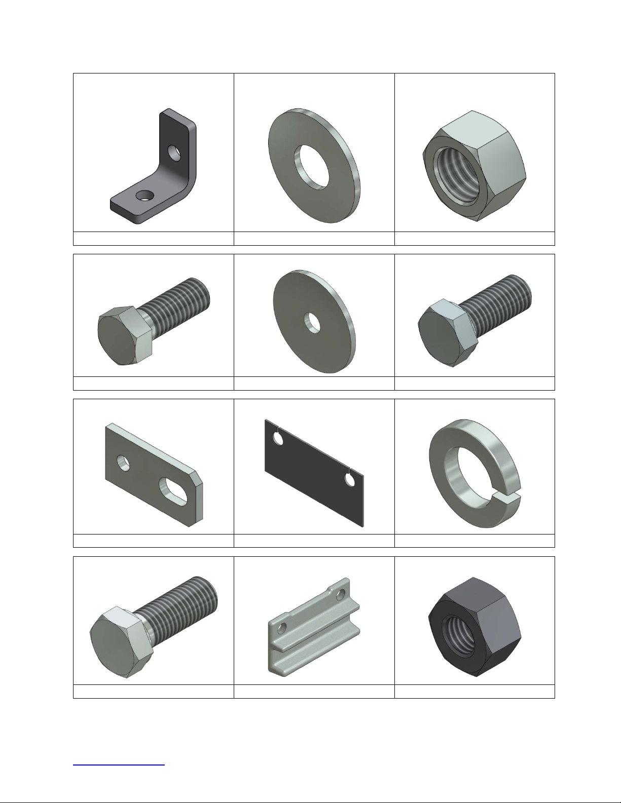
Bracket, Angle, 2” X 1”,
W/Holes
Washer, Flat 3/8” X 1” Nut, Hex, 3/8”
617387 118036 115960
Bolt, Hex, 3/8” X 1”,G5 Washer, Fender, 3/8” X 2” Bolt, Hex, 5/8” X 1 1/2", G5
113596 118038 113654
Bracket, Pull-Out Shim Kit, 1/8” X 3 5/8” X 8”(2) Washer, Lock, 3/4"
605535 614050 118089
Bolt, Hex, 3/4" X 2”, G8 Monorail Guide Nut, Heavy Hex, 3/4”
113555 611368 003704
* Parts in red are included in assemblies.
trinityhighway.com 10 Revision D September 2019
Page 12
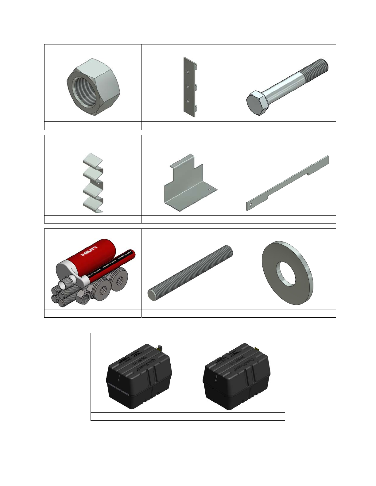
Nut, Heavy Hex, 5/8” Hinge Plate, Fender Panel Bolt, Hex, 5/8” X 4”, G5
003354 610172 113666
Panel, Side, QG Bracket, Cartridge Support
TS B/U
Locking Bar, Cartridge
Support
611898 605447 611266
Anchor Kit, Hilti, 3/4” X 7” (4) * Stud, 3/4” X 7”, G5 Washer, Flat, 3/4” X 2”
619316 117542 118027
*See Trinity Highway Approved Adhesive Anchoring System section on page 16.
Cartridge Assy, Type I Cartridge Assy, Type II
606027 606029
* Parts in red are included in assemblies.
trinityhighway.com 11 Revision D September 2019
Page 13
Foundation/Anchoring
Important: It is the responsibility of the local DOT or appropriate authority to
ensure this assembly conforms to the AASHTO Roadside Design Guide.
Warning: It is the responsibility of the installer to ensure that your assembly
procedure meets all appropriate Occupational Safety and Health Administration
(OSHA) and local standards.
Asphalt Installations
®
QuadGuard
construction zones on asphalt. Assemblies on Asphalt Concrete (“A.C.”) must provide a minimum
of 3” [76 mm] layer of asphalt over a minimum of 3” [76 mm] layer of Portland Cement Concrete
(“P.C.C.”), 6” [152 mm] layer of asphalt over 6” [152 mm] layer of subbase, or 8” [203 mm] layer
of asphalt with no subbase.
Concrete Installations
For concrete installations, the QuadGuard
placed and cured concrete base (4000 psi [28 MPa] minimum). Orientation of the concrete base
and the attenuator must comply with the project plans or as otherwise determined by the project
engineer or appropriate highway authority.
The QuadGuard
anchorage:
II Narrow systems with a Tension-Strut Backup may be temporarily installed in
Important: Only 18” [460 mm] threaded rods, utilizing Trinity Highway approved
adhesive, can be used with asphalt foundations. Contact Customer Service for a
complete list of approved adhesives (p. 3).
®
II should be installed only on an existing or freshly
®
II may be installed on any of the following foundations using the specified
Foundation A: Concrete Pad or Roadway
Foundation: 6” [150 mm] minimum depth P.C.C.
Anchorage: Approved adhesive
with 7” [180 mm] studs 5 1/2” [140 mm] embedment
Foundation B: Asphalt over P.C.C.
Foundation: 3” [76 mm] minimum A.C. over 3” [76 mm] minimum P.C.C.
Anchorage: Length of anchor required is 18” [460 mm] 16 1/2” [420 mm] embedment
Foundation C: Asphalt over Compacted Subbase (“C.S.”)
Foundation: 6” [150 mm] minimum A.C. over 6” [150 mm] minimum C.S.
Anchorage: Approved adhesive with 18” [460 mm] studs 16 1/2” [420 mm] embedment
Foundation D: Asphalt Only
Foundation: 8” [200 mm] minimum A.C.
Anchorage: Approved adhesive with 18” [460 mm] studs - 16 1/2” [420 mm] embedment
Important: Systems mounted on asphalt must be replaced and mounted on
fresh, undisturbed asphalt if more than 10% of anchors are found to be loose,
broken, or show signs of pull out. If 10% or fewer anchors are damaged, replace
the damaged anchors in the existing asphalt. Anchor bolts used on systems
mounted on asphalt must be inspected every six months. See Post Impact
Instructions and Maintenance and Repair instructions on page 58.
trinityhighway.com 12 Revision D September 2019
Page 14

Recommended Tools
Documentation
Manufacturer’s Assembly Manual
Manufacturer’s Drawing Package
Personal Protective Equipment
Eye Protection
Gloves
Safety Toe Shoes
Cutting Equipment
Rotary Hammer Drill
Rebar Cutting Bit
Concrete Drill Bits – 7/8” [22 mm] (Double-Fluted)
Grinder, Hacksaw or Torch (optional)
Drill Bits 1/16” through 7/8”
Important: Trinity Highway recommends using double-fluted drill bits to achieve
optimum tensile strength when applying an approved adhesive to the anchoring
system (p. 16).
Hammers
Sledgehammer
Standard hammer
Wrenches
Heavy Duty 1/2” drive impact wrench
1/2" drive Sockets: 9/16", 11/16", 3/4", 15/16", 1 1/8", 1 1/4"
1/2" drive Deep Well Sockets: 15/16", 1 1/4”
1/2" drive Ratchet and Attachments
1/2" drive Breaker Bar – 24” long
1/2" drive Torque Wrench: 200 ft-lb
Crescent Wrench: 12” [300 mm]
Allen Wrench: 3/8”
Important: Trinity Highway makes no recommendation whether use or
reuse of any part of the system is appropriate or acceptable following an
impact. It is the sole responsibility of the project engineer and/or the local
highway authority and its engineers to make that determination. It is critical
that you inspect this product after assembly is complete to make certain that
the instructions provided in this manual have been strictly followed.
trinityhighway.com 13 Revision D September 2019
Page 15

Miscellaneous
Traffic Control Equipment
Lifting and moving equipment (A lifting device is preferred although a forklift can be used.)
Minimum 5,000 lb. capacity required.
Air Compressor (100 psi minimum) and Generator (5 kW)
Long Pry Bar
Drift Pin 12” [300 mm]
Center Punch
Tape Measure 25’ [7.5 m]
Chalk Line
Concrete Marking Pencil
7/8” Diameter steel tube brush for cleaning drilled boreholes
Rags, water, and solvent for clean up
Note: The above list of tools is a general recommendation and should not be considered
an exhaustive list. Depending on specific site conditions and the complexity of the
assembly specified by the appropriate highway authority the required tools may vary.
Decisions as to what tools are needed to perform the assembly properly are entirely the
responsibility of the specifying highway authority and the authority’s selected contractor
performing the assembly of the system at the authority’s specified assembly site.
trinityhighway.com 14 Revision D September 2019
Page 16
Site Preparation/Foundation
A QuadGuard® II system should be assembled only on an existing or freshly placed and cured
concrete base (28 MPa [4000 psi] minimum). Location and orientation of the concrete base and
attenuator must comply with project plans or as otherwise determined by the local highway
authority.
Recommended dimension and reinforcement specifications for new concrete foundations are
provided in Trinity Highway concrete foundation drawings, supplied with the system. The system
may be assembled on a non-reinforced concrete roadway (minimum 8” [200 mm] thick).
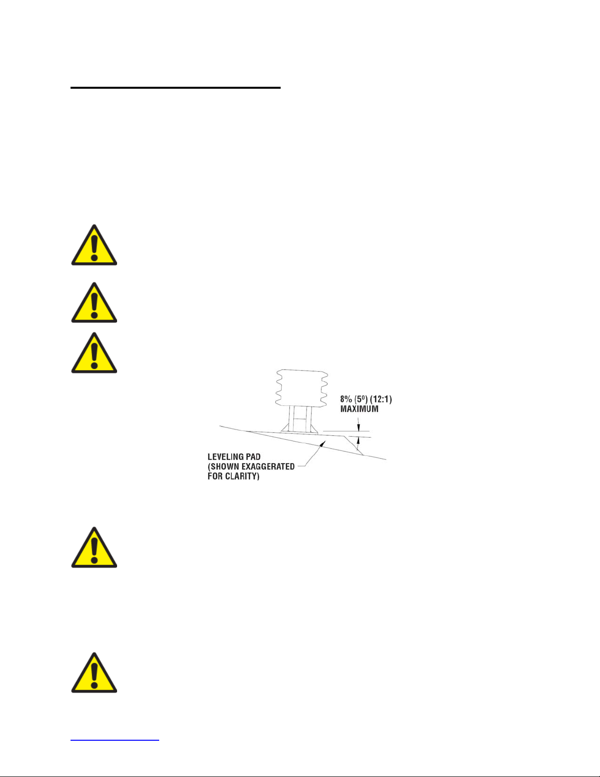
Deployment cross-slope shall not exceed 8% and should not twist more than 2% over the length
of the system; the foundation surface shall have a light broom finish.
Warning:
location for the QuadGuard
Guide. Trinity Highway is not responsible for choosing the location for system
placement.
Warning:
by the state or specifying agency pursuant to the AASHTO Roadside Design
Guide.
Caution:
the concrete anchor bolts.
It is the responsibility of the appropriate highway authority to select the
Ensure proper site grading for QuadGuard® II placement as directed
Accurate placement of all steel rebar is critical to avoid interference with
®
II in accordance with the AASHTO Roadside Design
Figure 1
Cross-Slope
Warning:
operation of the attenuator. Upon impact, the Fender Panels are designed to
telescope rearward and extend beyond the rigid Backup as much as 30” [760 mm]
from their pre-impact location. Position the Backup so that the rear ends of the last
Fender Panels are a minimum of 30” [760 mm] forward of objects that would
otherwise interfere with movement of the rearmost Fender Panels. Failure to
comply with this requirement is likely to result in system performance that has not
been crash tested pursuant to NCHRP Report 350 criteria and may also cause
component damage which will necessitate maintenance or replacement of the
system.
Important:
to ensure the instructions provided in this manual have been strictly followed.
trinityhighway.com 15 Revision D September 2019
Location of the Backup in relation to nearby objects will affect the
It is critical that you inspect this product after assembly is complete
Page 17
Trinity Highway Approved Adhesive Anchoring System
A Trinity Highway approved adhesive anchoring system is required to securely anchor crash
cushions. Each approved adhesive kit contains adhesive, studs, nuts and washers. Both vertical
and horizontal assemblies are possible using an approved adhesive anchoring system.
Vertical Assemblies
Note: Read all Trinity Highway approved adhesive instructions before starting.
1) Prepare the Concrete Foundation
Warning: Do not allow anchoring adhesive to contact skin or eyes. See safety
data sheet supplied with adhesive kit for first-aid procedures. Use only in wellventilated area. Do not use near open flame.
Warning: Wear gloves and eye protection during application.
®
The studs that anchor the QuadGuard
foundation must be those shipped in the kit or of high strength steel (120,000 psi [830 MPa]
minimum tensile strength or equal). These studs must be set in minimum 4000 psi [28 MPa]
concrete. Allow the concrete to cure a minimum of seven days before applying anchoring
adhesive.
II Backup and/or Monorail sections to the concrete
2) Drill Boreholes
Caution: It is the responsibility of the installer to consult OSHA silica
respiratory standard 29 CFR 1910.134 for debris removal from borehole(s)
and use Trinity Highway approved adhesive to achieve optimum tensile
strength. Do not use diamond drill bits for drilling boreholes.
Use the Monorail(s) and Tension Strut Backup as drilling templates. Use a rotary hammer drill
to drill the boreholes 7/8” [22 mm] diameter to the recommended depth. See the approved
adhesive instructions provided with your kit. Check to ensure each borehole is drilled to the
proper depth and aligned with the part to be anchored per chart below.
Anchoring Information
Stud Size: Orientation Bit Size Minimum Depth Torque Medium
3/4”x 6 1/2" Horizontal 7/8” [22 mm] 5 1/4” [133 mm] Manufacturer Spec Concrete
3/4”x 7" Vertical 7/8” [22 mm] 5 3/4” [145 mm] Manufacturer Spec Concrete
3/4”x 18" Vertical 7/8” [22 mm] 16 3/4” [425 mm] 10 ft-lb [15 N-m] Asphalt
Important: When mounting on asphalt, initial torque shall be as shown
above. Due to the properties of asphalt, anchors may loosen over time. For
this reason Trinity Highway recommends anchoring to asphalt only at
temporary locations. It is recommended to re-torque anchors in asphalt
every six (6) months to the proper initial torque specified.
trinityhighway.com 16 Revision D September 2019
Page 18
3) Clean the Boreholes
Blow the concrete dust from the borehole using oil-free compressed air. Thoroughly brush it
with a 7/8” diameter steel bristle tube brush and then blow it out again. If the borehole is wet,
completely flush it with water while brushing and then blow it clean to remove all water using
oil-free compressed air.
Note: Use of the Trinity Highway approved vacuum drilling equipment is authorized to replace
the blowing and brushing requirement of Step 3.
4) Apply Approved Adhesive
Fill the borehole 100% full.
Caution: Fill borehole 100% full so it is even with the pavement surface per
manufacturer’s instructions.
5) Add Nuts to Anchor Studs
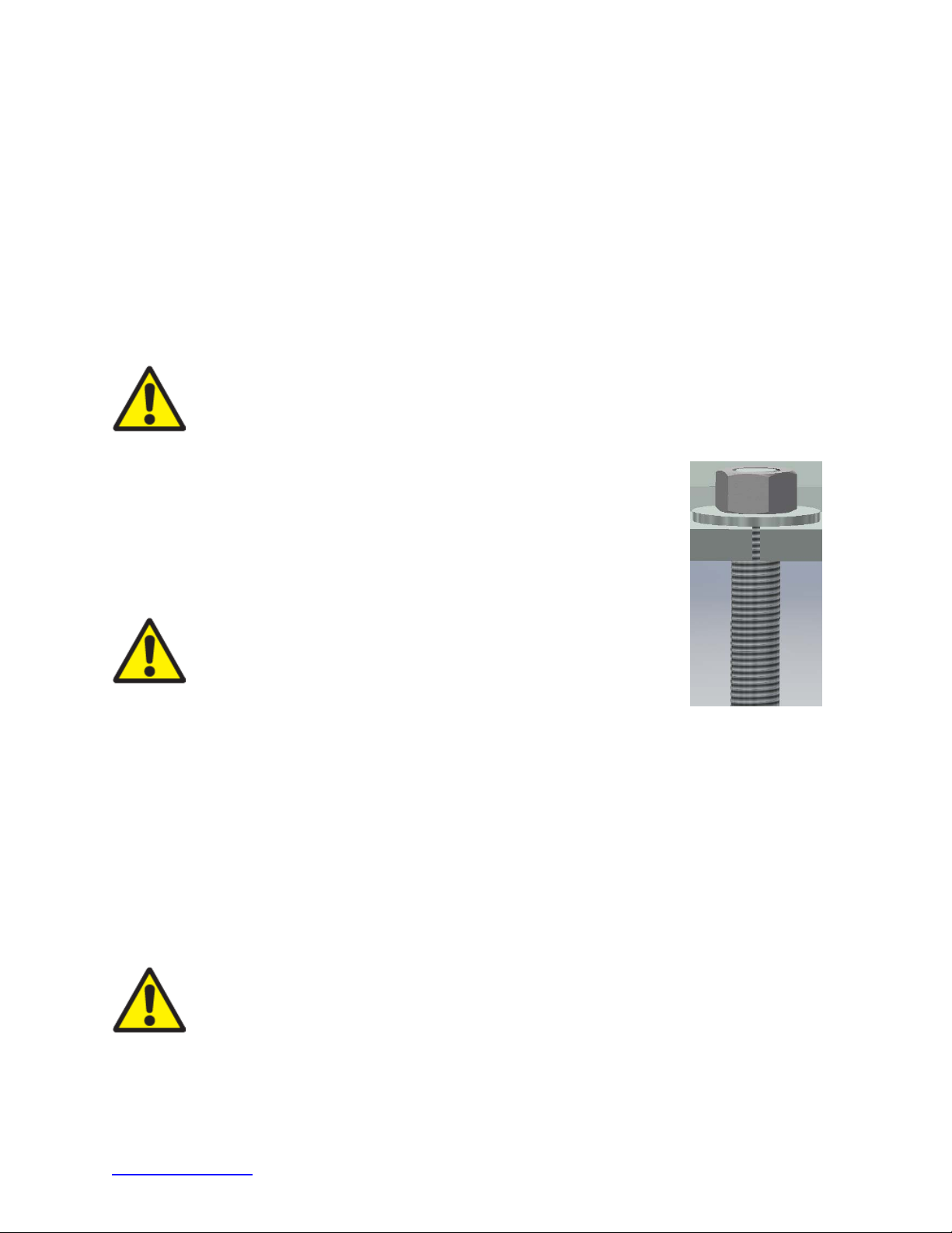
Place a flat washer onto the stud then thread a nut on until the end of
the stud is flush with the nut (Figure 2).
6) Insert Studs in Boreholes and Wait for Adhesive to Cure
Push the stud down through the part to be anchored and into the
borehole.
Caution: Do not disturb or load the stud until the approved
adhesive material has hardened (see instructions supplied
with the approved adhesive kit).
7) Torque the Nuts
Once the adhesive has fully cured, torque the nut to the adhesive
manufacturer’s recommended values.
Figure 2
Vertical Application
(Before Applied Torque)
Anchor Assembly Cautions
1) Steel rebar
If steel rebar is encountered while drilling an anchor bolt borehole, apply one of the following
solutions:
A) Use a rebar drill bit for the rebar only and then switch back to the concrete bit to finish
drilling into the underlying concrete until the proper borehole depth is reached.
Caution: Do not drill through rebar without first obtaining permission to do so
from the project engineer.
B) Drill a new borehole down at an angle past the rebar to the proper depth. Anchor the
stud by completely filling both boreholes with an approved adhesive.
trinityhighway.com 17 Revision D September 2019
Page 19
Horizontal Assemblies
The horizontal approved adhesive kit is the same as the vertical kit.
Caution:
manufacturer’s instructions.
1) Follow the instructions supplied with your approved adhesive kit
Apply approved adhesive to each anchor per instructions.
2) Add the Washers and Nuts
Put washer and nut on stud so the nut is flush with end of stud.
3) Insert each Stud with Washer and Nut into Borehole
Push stud with washer and nut into borehole.
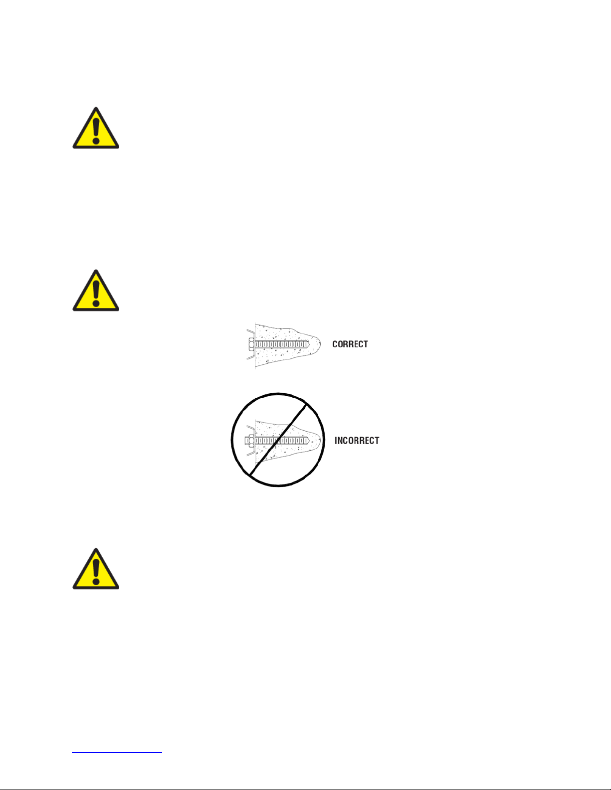
Important:
horizontal applications prior to tightening (Figure 3).
Fill borehole 100% full so it is even with the surface of the hole per
The stud should be flush with the top of the nut in both vertical and
Horizontal Application
(Before Applied Torque)
Warning:
has hardened (see approved adhesive kit instructions for cure times and
torque values).
4) Torque the nuts
Once the adhesive has fully cured, torque nut(s) to the approved adhesive manufacturing
specification.
trinityhighway.com 18 Revision D September 2019
Do not disturb or load the stud until the approved adhesive material
Figure 3
Page 20
7
QG2100126
Figure 4 Plans & Elevation
(Five Bay systems with Tension Strut Backups shown, except as noted)
Key
1) Cartridge
2) Diaphragm
3) Quad-Beam Fender Panel
4) Nose
5) Monorail
6) Backup
7) Side Panel
trinityhighway.com 19 Revision D September 2019
Page 21
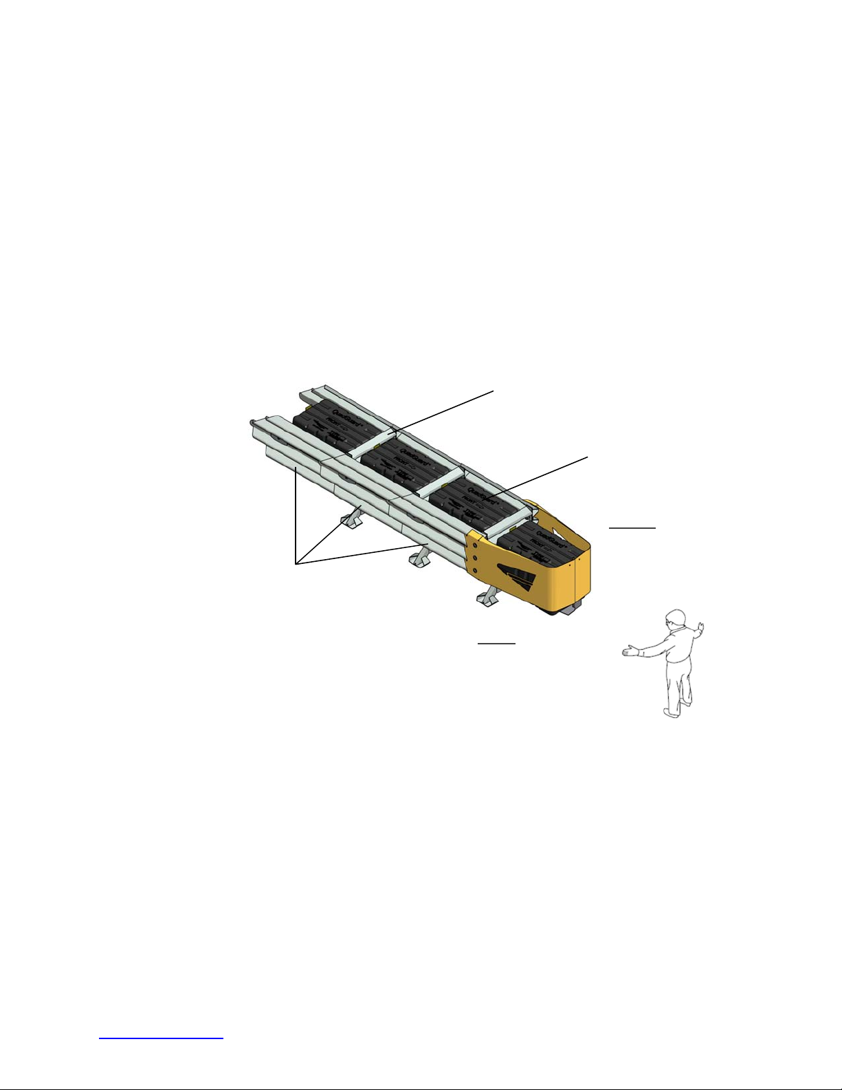
How to Determine Left/Right
To determine left from right when ordering parts, stand in front of the system facing the roadside
feature. Your left is the system’s left and your right is the system’s right.
Counting the Number of Bays
One Bay consists of one Cartridge, one Diaphragm, two Fender Panels, etc. The Nose section is
not considered a Bay, though there is a Cartridge in the Nose of each system (pp. 63 & 64).
Note:
the system. To determine number of Bays, count Fender Panels on one side (Figure 5). The
Three Bay system is shown below.
There will always be one more Cartridge in the system than the number of Bays in
REAR
BAY
BAY
FENDER PANELS
DIAPHRAGM
BAY
CARTRIDGE
RIGHT
NOSE
FRONT
LEFT
Figure 5
System Orientation
trinityhighway.com 20 Revision D September 2019
Page 22
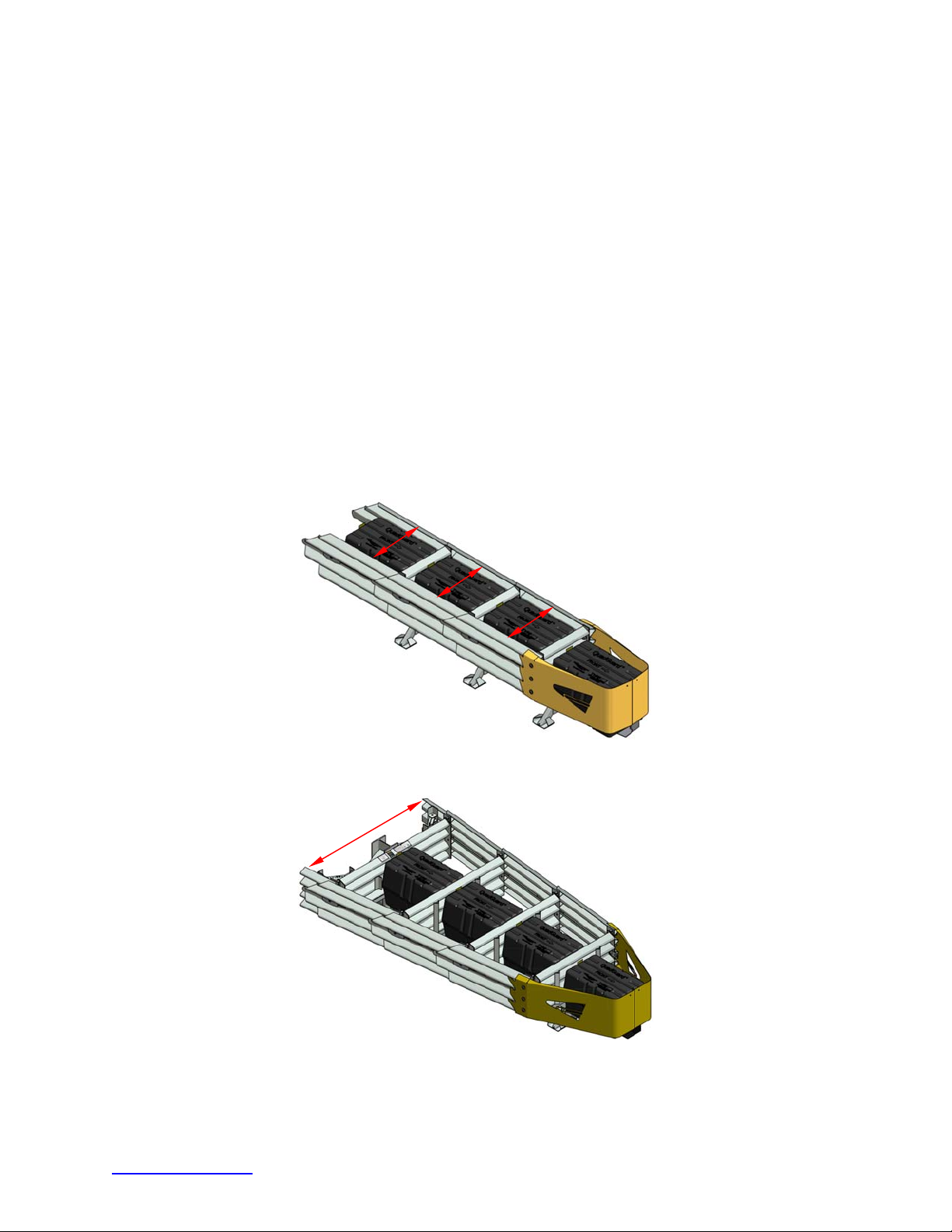
Measuring the Width
The QuadGuard® II system is available in seven (7) nominal widths:
24” [610 mm]
30” [760 mm]
36” [915 mm]
48” [1219 mm]
69” [1755 mm] – (Minimum 3 Bays Required)
90” [2285 mm] – (Minimum 3 Bays Required)
126” [3200 mm] – (Minimum 6 Bays Required)
The nominal width of a Narrow (parallel) system is the width of the Backup diaphragm (Figure
6).
The nominal width of a Wide (flared) system is the width at the location shown in Figure 7.
The outside or overall width of the system is approximately 6” [150 mm] to 9” [230 mm] wider than
the nominal width.
Figure 6
Narrow (Parallel) System
Figure 7
Wide (Flared) System
trinityhighway.com 21 Revision D September 2019
Page 23
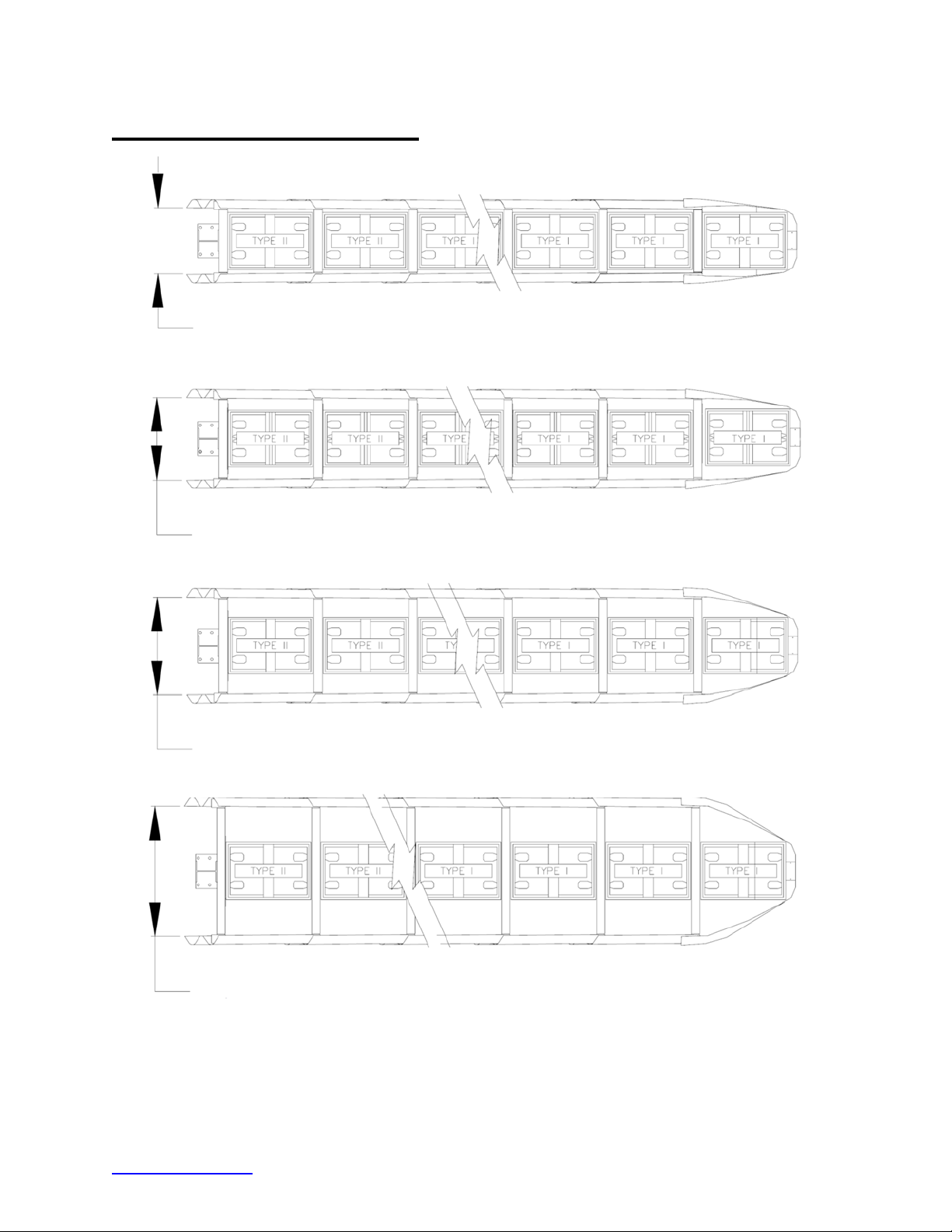
Narrow (Parallel) Systems
610 mm [24”] Model No. QG2 _ _24
760 mm [30”] Model No. QG2 _ _30
915 mm [36”] Model No. QG2 _ _36
1219 mm [48”] Model No. QG2 _ _48
Narrow System(s) and Model Numbers
trinityhighway.com 22 Revision D September 2019
Figure 8
Page 24
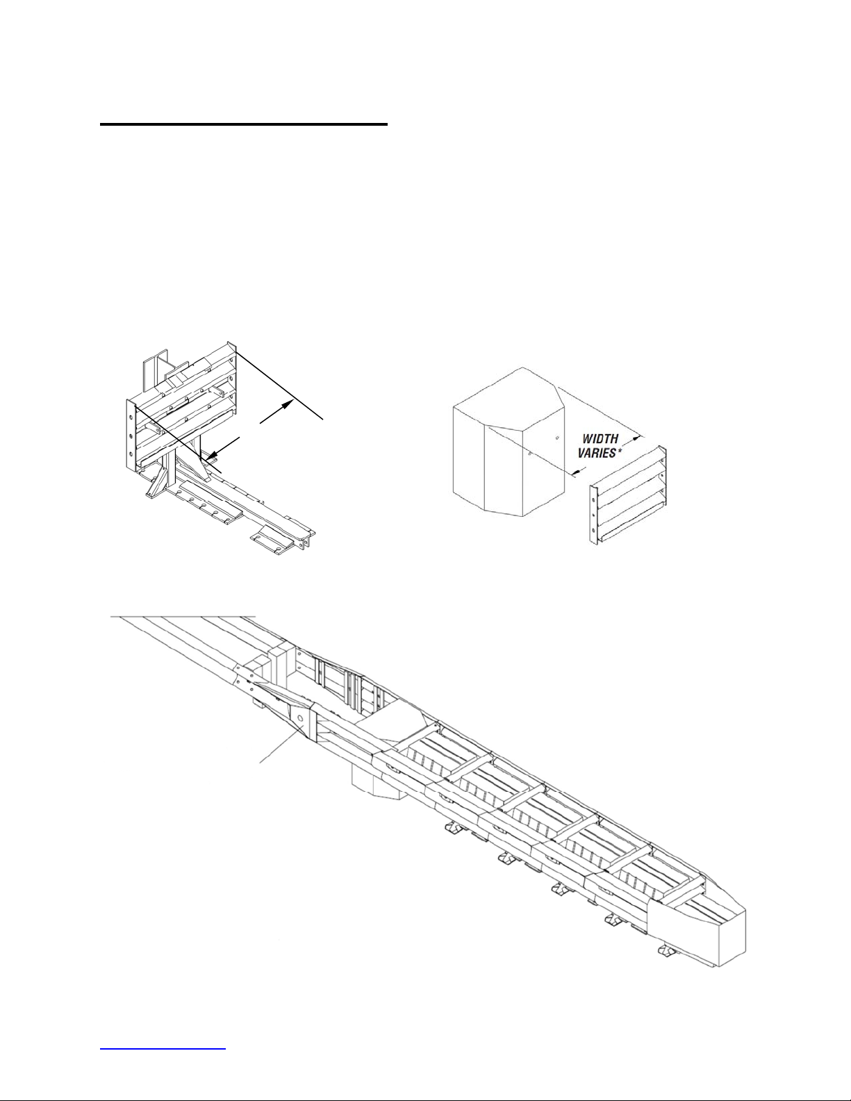
Assemble Narrow (Parallel)
Determine Backup and Transition Type
The QuadGuard® II is available with a Tension Strut Backup or a Concrete Backup. Refer
to Figures 9 and 10, along with the Backup Assembly drawing, to determine which type of
Backup is being deployed.
A Transition Panel or Side Panel must be used on each side of the Backup. A Side Panel
is not needed when a Transition Panel is used. Several types of Transitions are available
for use with the QuadGuard
Package to determine which type of Panels to attach.
®
II. Refer to Figures 11 - 16 and the Manufacturer’s Drawing
610 mm [24”]
760 mm [30”]
915 mm [36”]
1219 mm [48”]
WIDTH
VARIES*
Figure 9
Tension Strut Backup
*610 mm [24”]
*760 mm [30”]
*915 mm [36”]
*1219 mm [48”]
Figure 10
Concrete Backup
QUAD-BEAM TO W-BEAM
TRANSITION PANEL
Figure 11
Transitioning the QuadGuard
trinityhighway.com 23 Revision D September 2019
®
II
Page 25
Note:
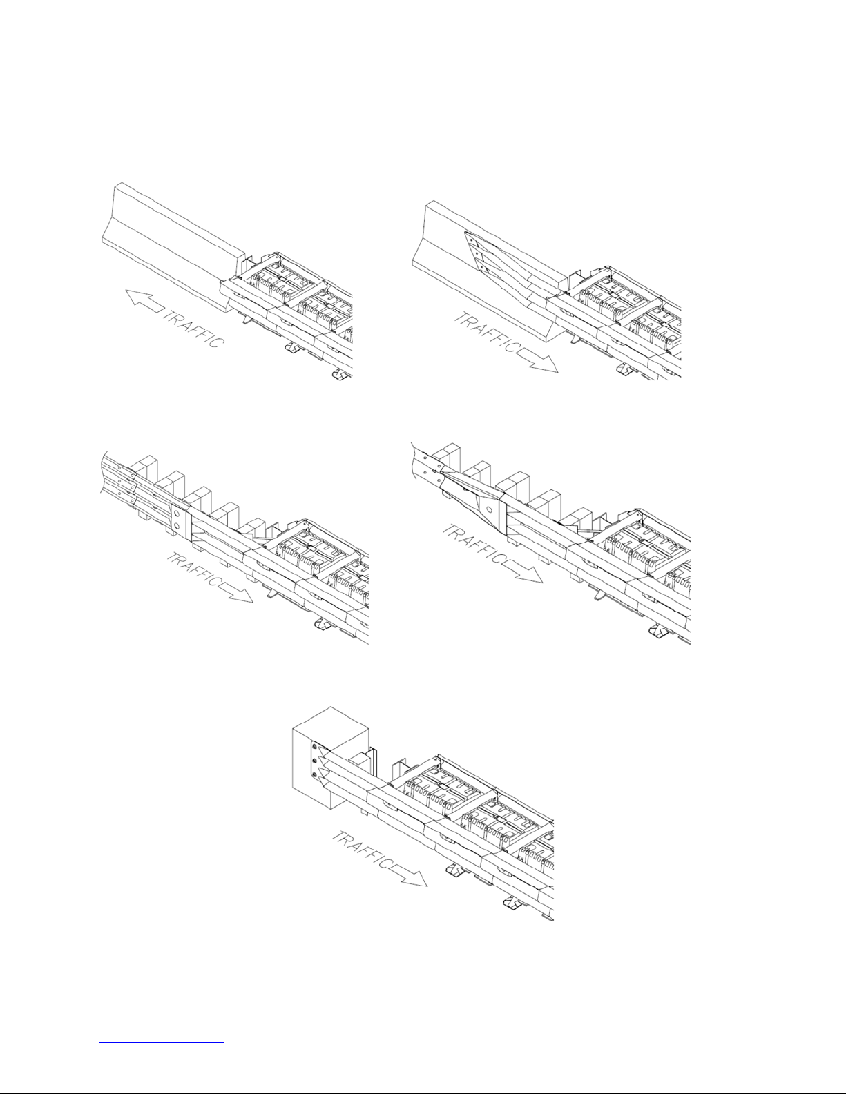
The proper Transition Panel or Side Panel must be used for impact performance of the
system. The correct Panel(s) to use will depend on the direction of traffic and what type of barrier
or roadside obstacle the QuadGuard
®
II is shielding. Contact Customer Service prior to
deployment if you have any questions (p. 3).
Figure 12
No Transition
Quad-Beam to Safety Shape Barrier
Figure 13
Quad-Beam to Thrie-Beam
Figure 14
Quad-Beam to W-Beam
Figure 15
Quad-Beam End Shoe
Figure 16
trinityhighway.com 24 Revision D September 2019
Page 26
1) Mark System Location
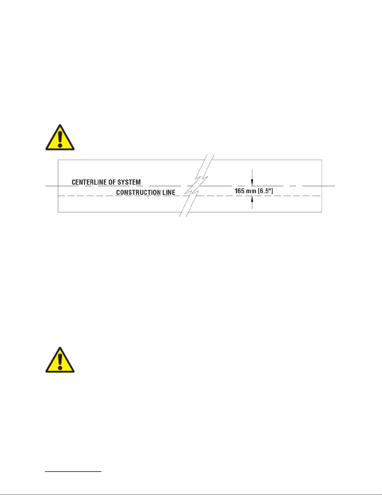
Locate the centerline of the system by measuring the proper offset from the roadside
feature. See the Manufacturer’s Drawing Package supplied with the system. Place chalk
line to mark the centerline of the system. Mark a construction line parallel to the center line
and offset 6.5” [165 mm] to one side as shown in Figure 17. The edge of the Monorail will
be positioned on this line.
Note:
The concrete foundation shall comply with the Manufacturer’s Drawing Package supplied
with the system.
Warning:
Location of system with respect to the roadside obstacle is critical and
dependent on the type of Transition Panel used. See the Manufacturer’s Drawing
Package supplied with the system for details.
(Top view of concrete foundation)
Figure 17
2) Anchor the Backup
A) Concrete Backup Construction (Figure 18)
Locate Backup Face Plate using the Backup Assembly drawing. Verify that any applicable
Transition Panels fit properly before anchoring the Face Plate. Drill anchor boreholes
in the Concrete Backup using the Face Plate as a template. Anchor the Face Plate to the
Concrete Backup using an approved adhesive supplied with the QuadGuard
®
II (p. 16).
A Trinity Highway approved adhesive anchoring system is required to securely anchor crash
cushions and other common highway devices. Each approved adhesive kit contains
adhesive, studs, nuts and washers. Both vertical and horizontal assemblies are possible
using an approved adhesive anchoring system.
Warning:
Every hole in the Backup and Monorail must be anchored using an
approved adhesive (p. 16).
B) Tension Strut Backup Assembly (Figure 19)
Locate Tension Strut Backup and Monorail on foundation with side of Monorail on the
construction line (Figure 20 on p. 27). Verify that any applicable Transition Panels fit
properly before anchoring Backup. Drill 7/8” [22 mm] diameter by 5 3/4” [145 mm] deep
anchor boreholes in foundation using the Backup as template. Anchor the Backup to the
concrete foundation using an approved adhesive supplied with the QuadGuard II (p. 16).
trinityhighway.com 25 Revision D September 2019
Page 27
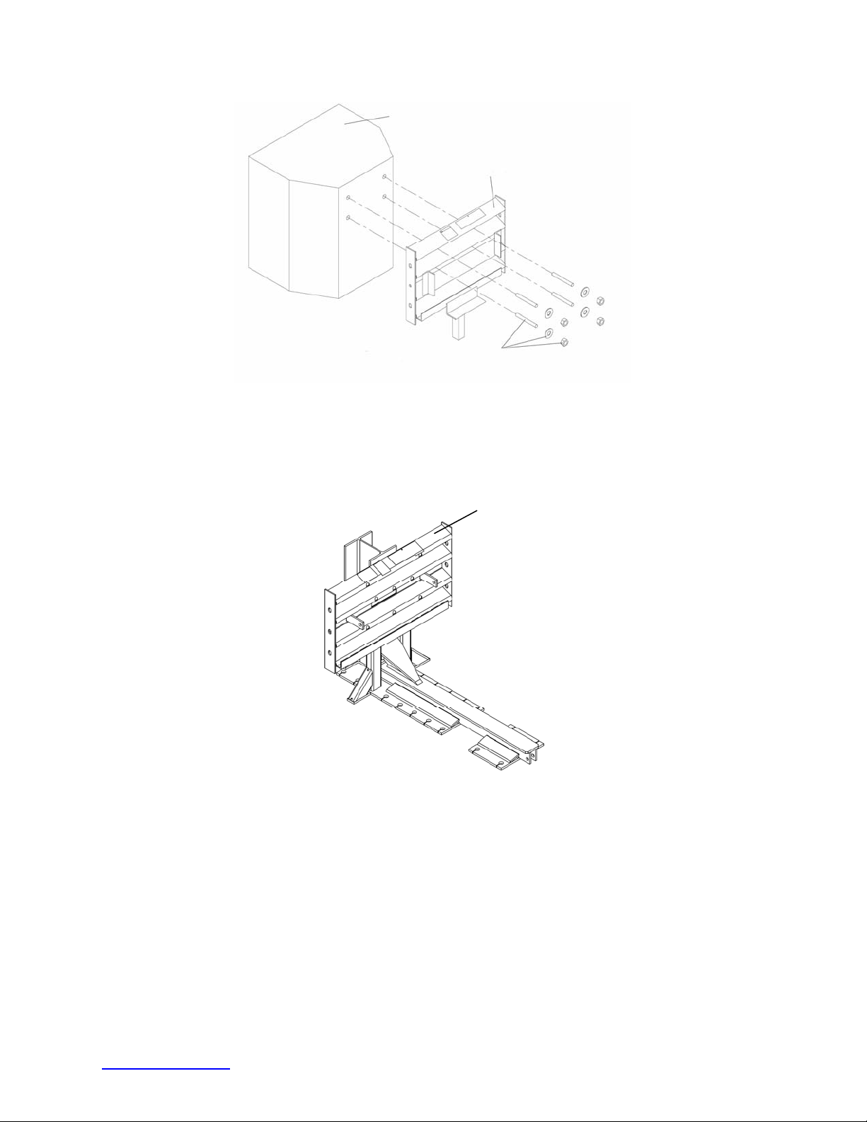
FULLY CURED CONCRETE BACKUP
A
SEE MANUFACTURER’S DRAWING PACKAGE
BACKUP FACE PLATE
PPROVED ADHESIVE WITH
3/4” X 6 1/2” STUD
Figure 18
Anchoring Backup Face Plate to
Concrete Backup
TENSION STRUT
Anchoring Tension Strut Backup
Figure 19
to Foundation
trinityhighway.com 26 Revision D September 2019
Page 28
3)
p
Anchor the Monorail
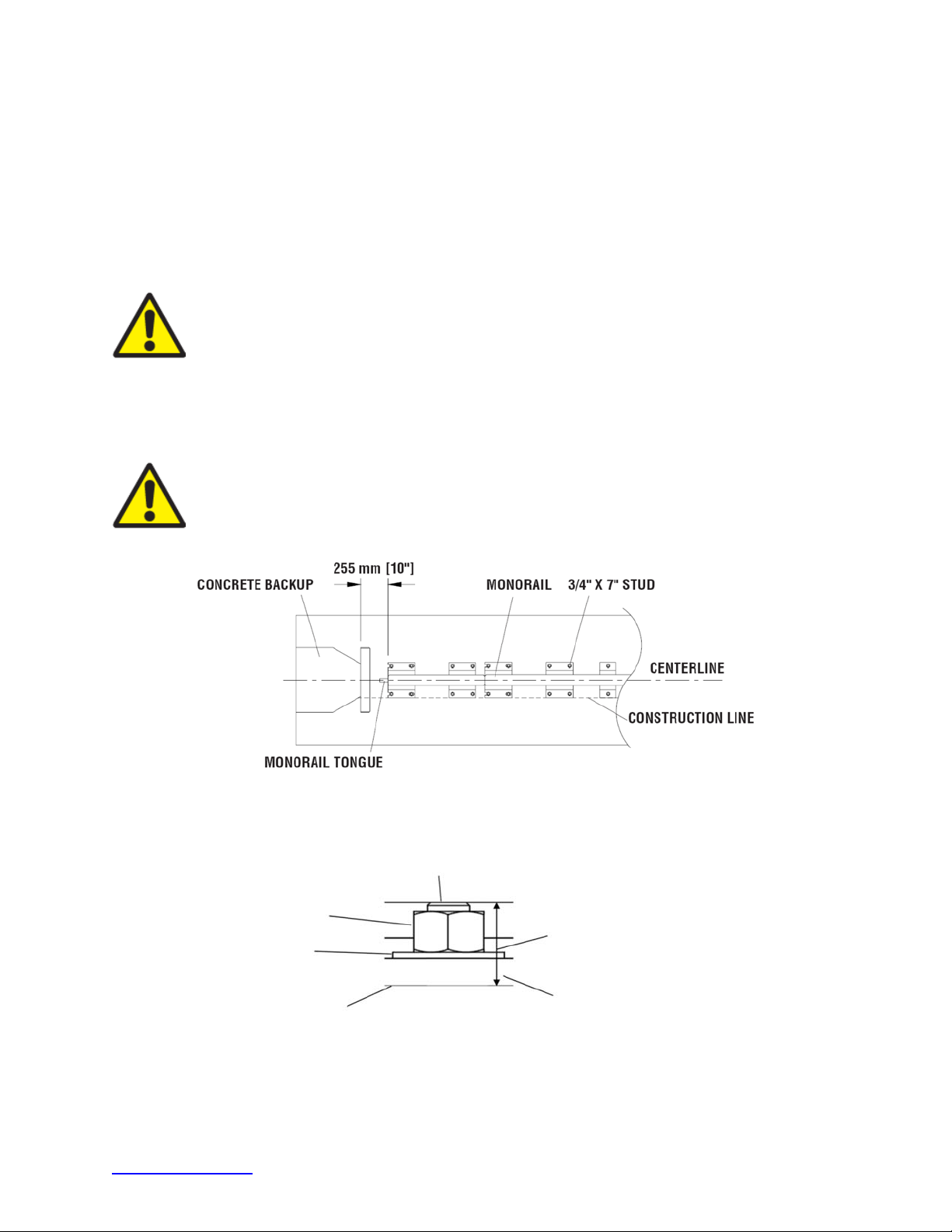
A) Monorail Placement for Concrete Backup (Figure 20)
Locate Monorail on foundation with side of Monorail on the construction line and rear edge
of Monorail foot 10” forward of front face of Concrete Backup (Figure 20).
Orient the Monorail so that the Monorail tongues face Backup (Figure 20).
Drill 7/8” [22 mm] diameter by 5 3/4” [145 mm] deep boreholes using the Monorail as a
template. Do not drill through foundation.
Warning:
Improper alignment at the Monorail Sections will prevent proper
system collapse during impact (Figure 23).
Anchor each Monorail section using an approved Trinity Highway adhesive kit. See Figure
20 and the approved adhesive instructions included with the adhesive kit. It is important to
attach each segment of Monorail in alignment from the back to the front of the system
(±1/4” [6 mm]).
Warning:
Every borehole and slot in Backup and Monorail must be anchored by
a stud using an approved adhesive.
Figure 20
Monorail Placement for Concrete Backu
ANCHOR
NUT
WASHER
ROADWAY
CAUTION: 40 MM [1.5”]
MAXIMUM STUD HEIGHT
(TORQUE APPLIED)
BACKUP OR MONORAIL
Figure 21
Proper Stud Height
(Torque Applied)
trinityhighway.com 27 Revision D September 2019
Page 29
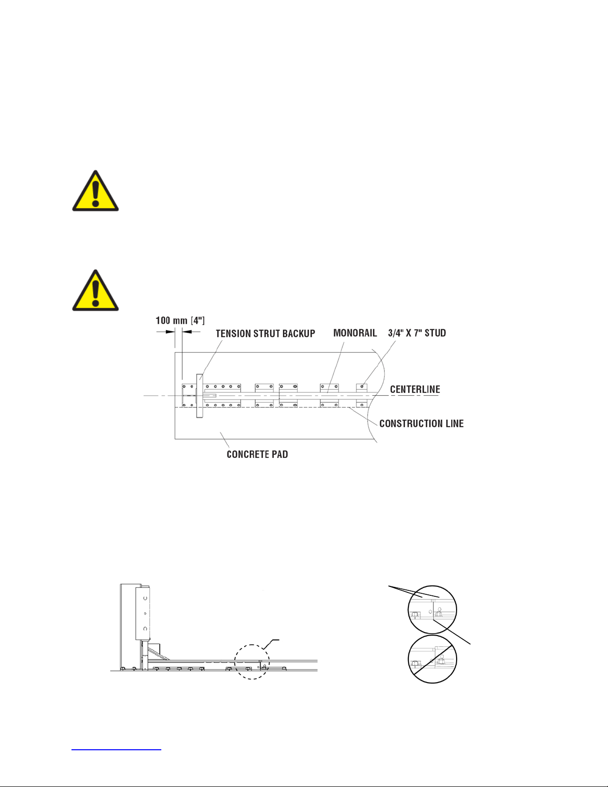
B) Monorail Placement for Tension Strut Backup (Figure 22)
Locate Monorail on foundation with side of Monorail on the construction line and rear edge
of Backup foot 4” forward of edge of foundation (Figure 22).
Orient the Monorail so that the Monorail tongues face the Backup (Figure 23).
Drill 7/8” [22 mm] diameter by 5 3/4” [145 mm] deep boreholes using the Monorail as a
template. Do not drill through foundation.
Warning:
Every borehole and slot in Backup and Monorail must be anchored by
a stud using a Trinity Highway approved adhesive.
Anchor each Monorail section using the Trinity Highway approved adhesive kits provided.
See Figure 21 and the approved adhesive instructions included with each kit. It is important
to attach each segment of Monorail in alignment from the back to the front of the system
(±1/4” [6 mm]).
Warning:
Improper alignment at the Monorail splice joints will prevent proper
system collapse during an impact (Figure 23).
Figure 22
Backup and Monorail Placement for Tension Strut Backup
It is important to align each segment of Monorail from the back to the front of the system
(±1/4” [6 mm]). Anchor each Monorail section using the provided Trinity Highway approved
adhesive kit.
Drill 7/8” [22 mm] diameter by 5 3/4” [145 mm] deep boreholes using the Monorail as a
template. Do not drill through foundation.
Top surfaces
must be flush
Tongues must be
Detail 23a
Fully Inserted
and Flush
Figure 23
Rail Height and Alignment
trinityhighway.com 28 Revision D September 2019
Page 30
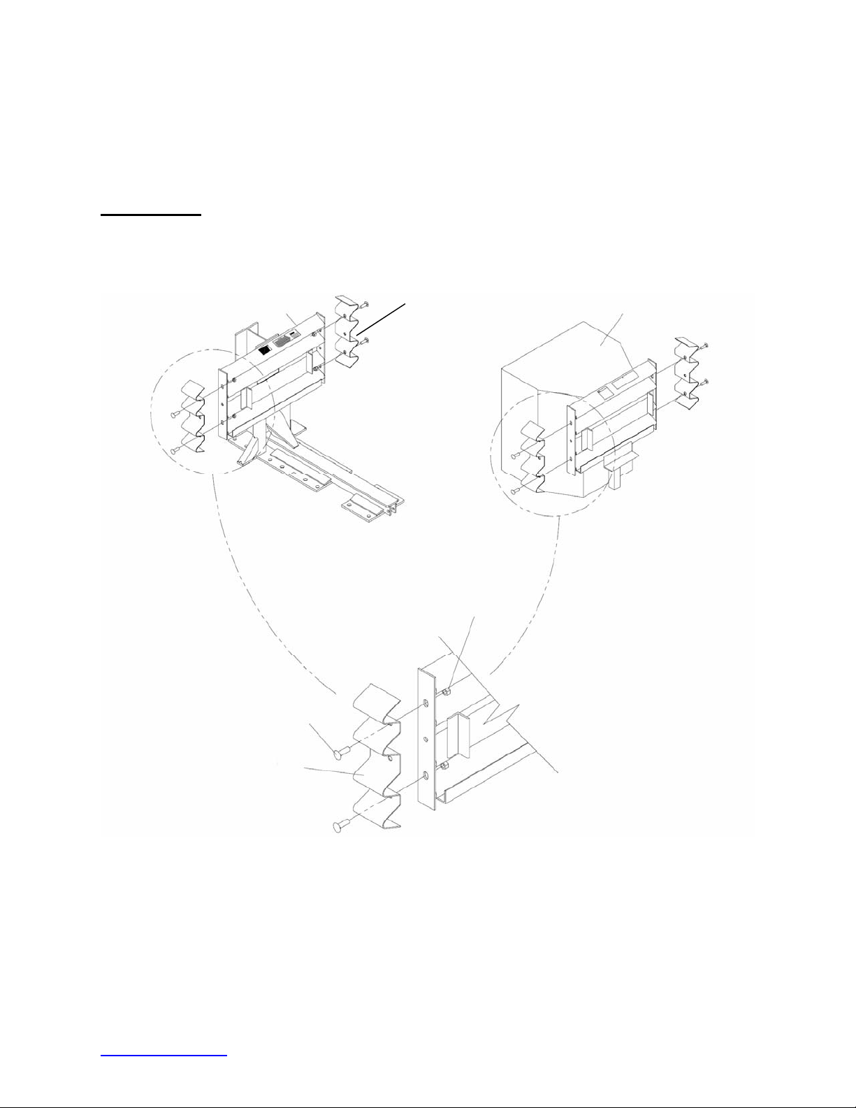
4) Attach Side Panels and/or Transition Panels to Backup Assembly
Attach Transition Panel or Side Panel to side of Backup using 5/8” X 2” rail bolt and 5/8” rail
nut (two places - top and bottom holes only). See Backup Assembly drawing(s) below.
Note: A Side Panel is not needed when a Transition Panel is used.
Assembly tip:
Use drift pin to align the center hole of the Panel with the center hole of the Backup before
inserting the rail bolts.
TENSION STRUT BACKUP
NARROW SIDE PANEL
5/8” RAIL NUT (2)
(FIGURE 28)
CONCRETE BACKUP
5/8” X 2 RAIL BOLT (2)
SIDE PANEL SHOWN HERE
IN SOME CASES, THIS WILL BE
A TRANSITION PANEL
(p. 24)
Side Panel/Transition Panel Attachment
Figure 24
trinityhighway.com 29 Revision D September 2019
Page 31
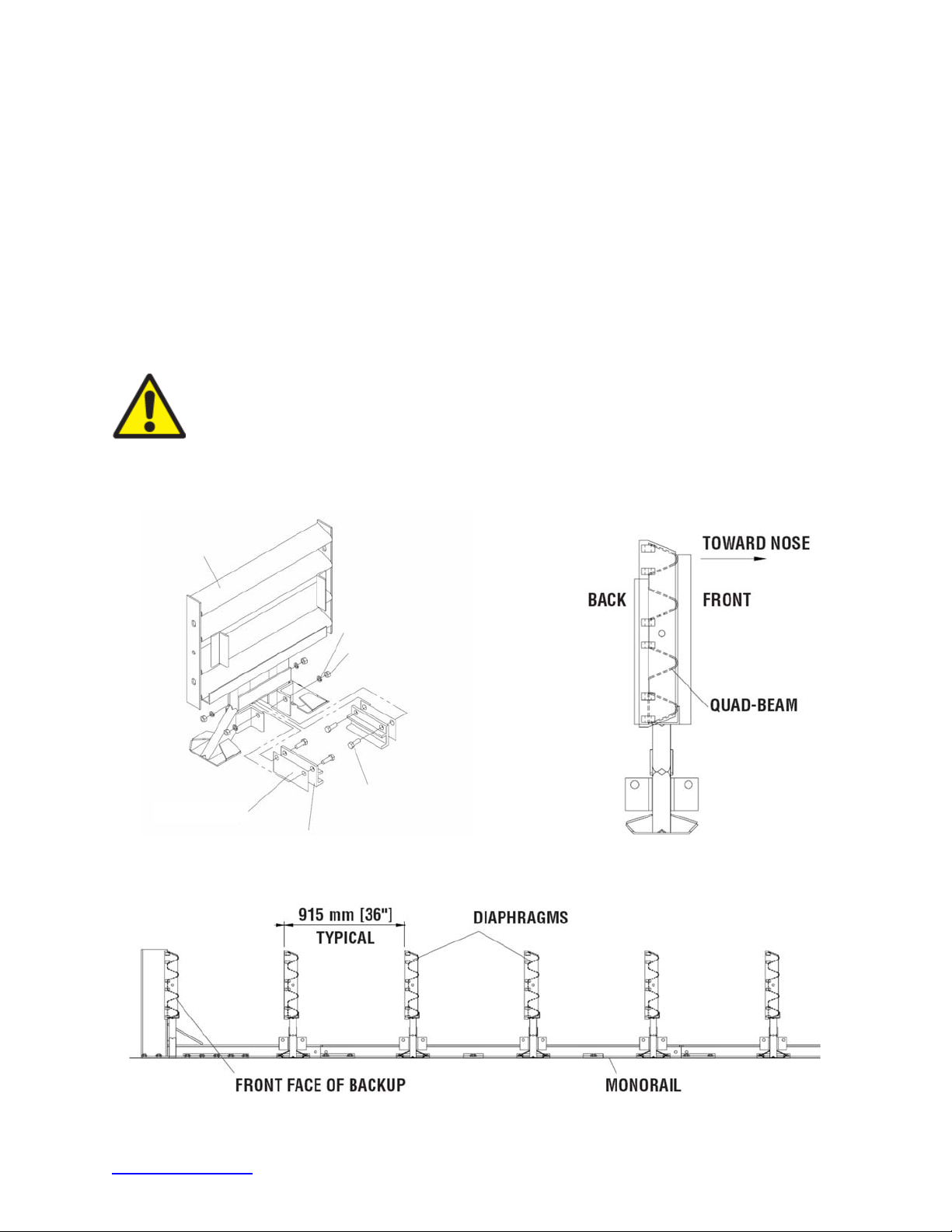
5) Attach Monorail Guides
Attach Monorail guides to Diaphragm as follows:
Insert 3/4" x 2” G8 hex bolt through Monorail guide and Diaphragm, oriented as shown in
Figure 25. Secure with 3/4" lock washer and 3/4" hex nut (typical 4 places). See also
Diaphragm Assembly drawing. Shims are sandwiched between the Rail Guide and
Diaphragm.
Repeat process for each Diaphragm.
6) Attach Diaphragms
Orient a Diaphragm so that the front face of the Diaphragm shape faces toward the Nose of
the system as shown in Figure 26.
Important:
Slide one Diaphragm all the way to the Backup to ensure the system
is able to collapse properly during impact. Once this has been verified, slide the
Diaphragm to approximately 36” [915 mm] in front of the Backup
Orient and slide all other Diaphragms onto Monorail and position each approximately as
shown in Figure 27.
DIAPHRAGM
MONORAIL GUIDE
Monorail Guide Attachment
SHIM
Figure 25
3/4” LOCK WASHER
3/4” HEX NUT
3/4” X 2 G8 HEX BOLT
Figure 26
Diaphragm Orientation
Bay 3
Figure 27
Bay 2
Bay 1
Nose
Diaphragm Spacing
trinityhighway.com 30 Revision D September 2019
Page 32
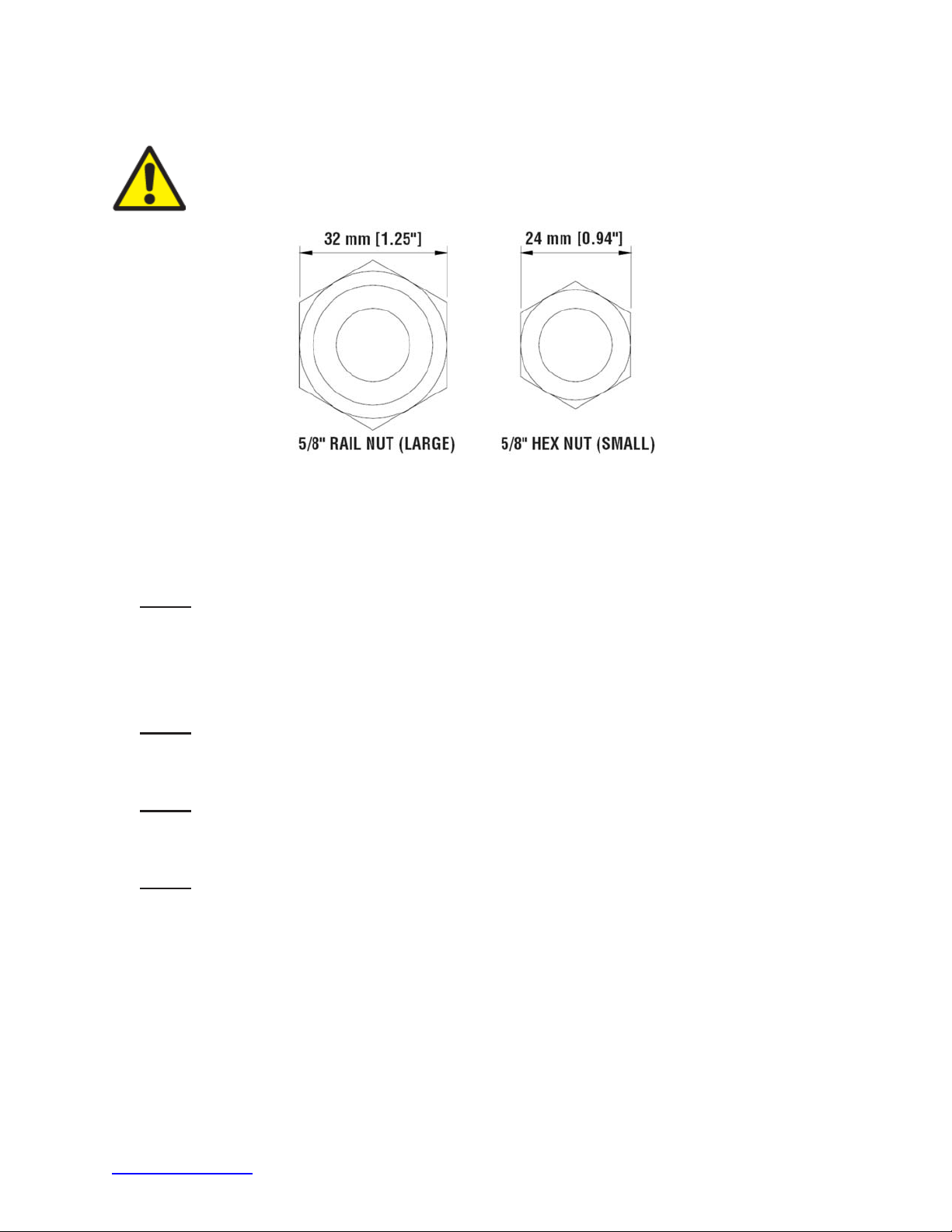
7) Attach Fender Panels
Important:
(Figure 28).
Starting at the Backup, attach left and right Fender Panels shown on page 32 and Fender
Panel Assembly drawing.
Step 1
Do not mix the 5/8” rail nuts (large) with the 5/8” hex nuts (small)
Figure 28
Rail Nuts are Oversize
Place the Fender Panel so that the center of the slot of the rearward Diaphragm is lined
up with the approximate center of the slot in the Fender Panel.
Install the Mushroom Washer Assembly as shown in Figure 29 and Detail 29a and
Detail 29b, but do not torque at this time. This (Step 1) helps to balance the Fender Panel.
Step 2
Slide the Fender Panel forward until the holes in the Fender Panel line up with the holes
in the forward Diaphragm.
Step 3
Use a drift pin to align the center hole of the Fender Panel with the center hole of the
Diaphragm.
Step 4
Attach the front of the Fender Panels to the next Diaphragm using two (2) rail bolts and
large rail nuts per side. Use only the top and bottom holes; leave the center hole open
until the next Fender Panel is attached.
trinityhighway.com 31 Revision D September 2019
Page 33
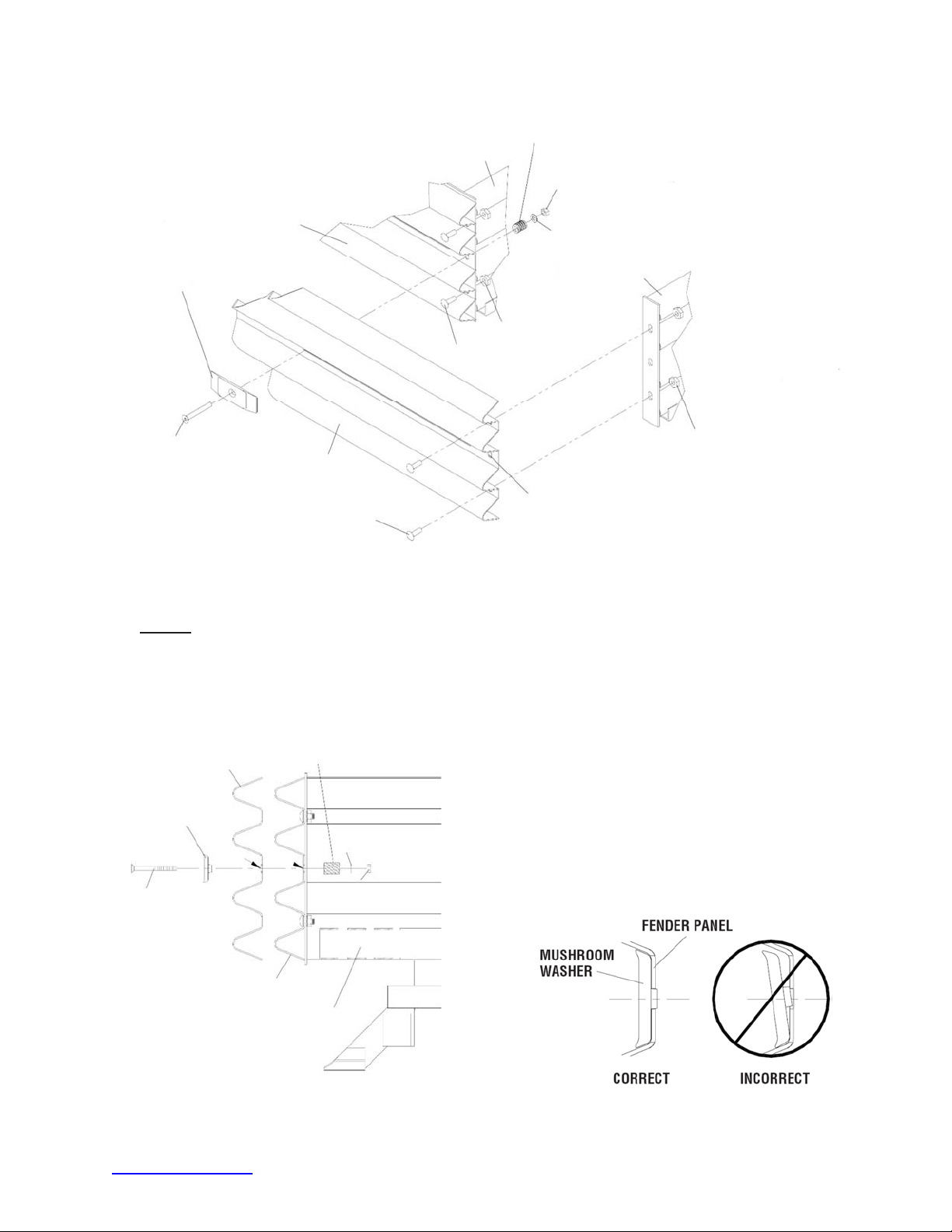
BACKUP OR DIAPHRAGM
1 1/2” SPRING
SIDE PANEL,
FENDER PANEL, OR
TRANSITION PANEL
MUSHROOM WASHER
5/8” X 5” FLATHEAD
SOCKET SCREW
Step 5
FENDER PANEL
5/8” RAIL BOLT
5/8” HEX NUT (SMALL)
5/8”X 1 3/4” FLAT WASHER
5/8” RAIL NUT (LARGE)
5/8” RAIL BOLT
KEEP CENTER HOLE EMPTY
FOR NEXT PANEL
Figure 29
Fender Panel Assembly
DIAPHRAGM
5/8” RAIL NUT (LARGE)
Ensure Mushroom Washer lays flat against the Fender Panel as shown in Figure 29b.
Standoff on Mushroom Washer must be seated completely through slot.
FENDER PANEL
MUSHROOM
WASHER
5/8” X 5” FLATHEAD
SOCKET SCREW
FENDER PANEL (ATTACHED)
BACKUP OR DIAPHRAGM
SLOT
Detail 29a
Mushroom Washer Attachment
1 1/2” SPRING
SLOT
5/8” HEX NUT (SMALL)
5/8” FLAT WASHER
Detail 29b
Mushroom Washer Orientation
trinityhighway.com 32 Revision D September 2019
Page 34
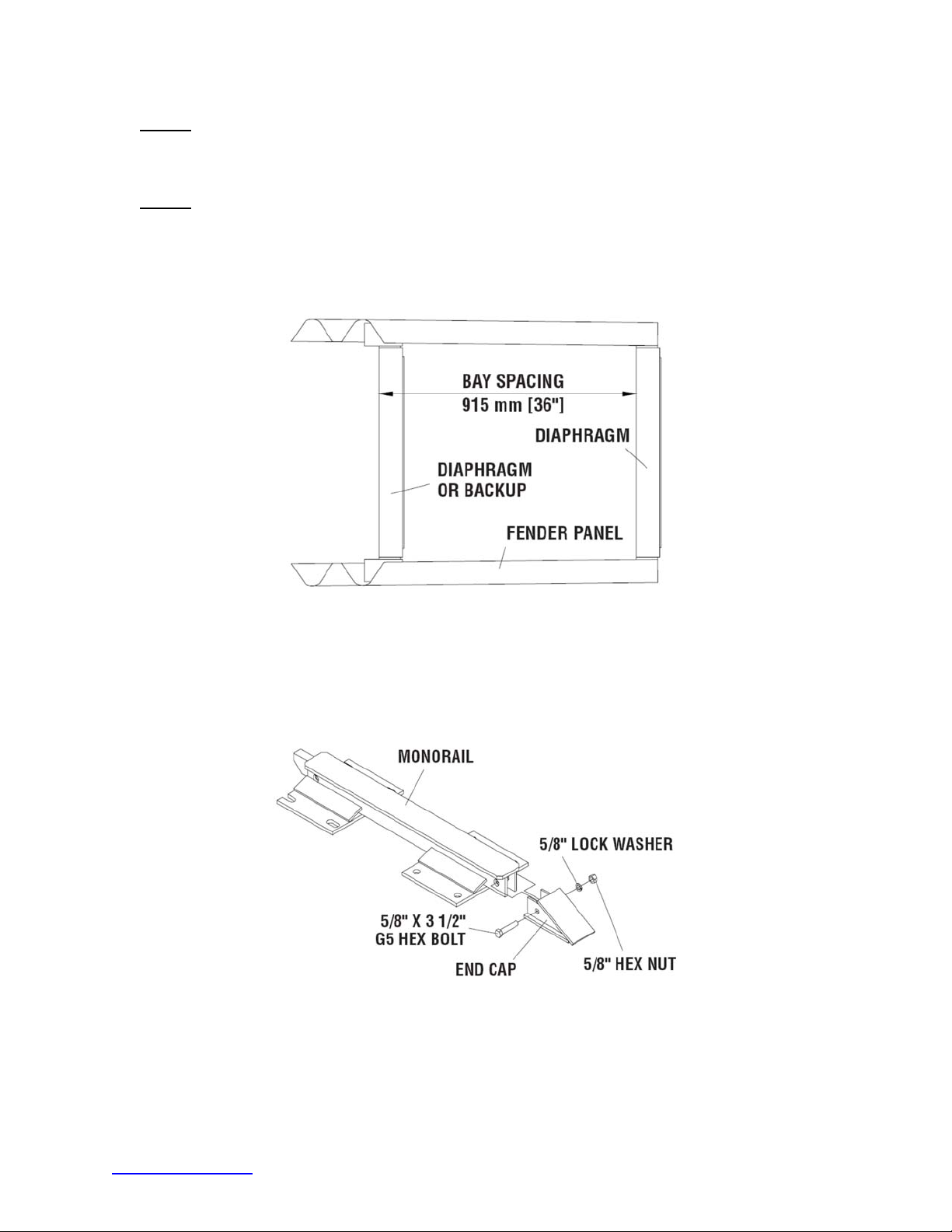
Step 6
Check Diaphragm spacing to ensure 36” [915 mm] between rear faces of consecutive
Diaphragms, as shown in Figure 30 and Fender Panel Assembly drawing.
Step 7
Once proper spacing has been achieved, tighten the Mushroom Washer Assembly (small
hex) nut until it reaches the end of the threads. Tighten rail nut (large hex) at the front of
the Fender Panels. Ensure rail bolt shoulder is seated within the Fender Panel slot.
Assemble the remaining Diaphragms and Fender Panels following the same procedures.
Proper Diaphragm Spacing
Figure 30
8) Attach End Cap (Figure 31)
Using a 5/8” x 3 1/2" G5 hex bolt, 5/8” hex nut, and 5/8” lock washer, attach the End Cap to
the front of the first Monorail segment.
Figure 31
Monorail End Cap Assembly
trinityhighway.com 33 Revision D September 2019
Page 35
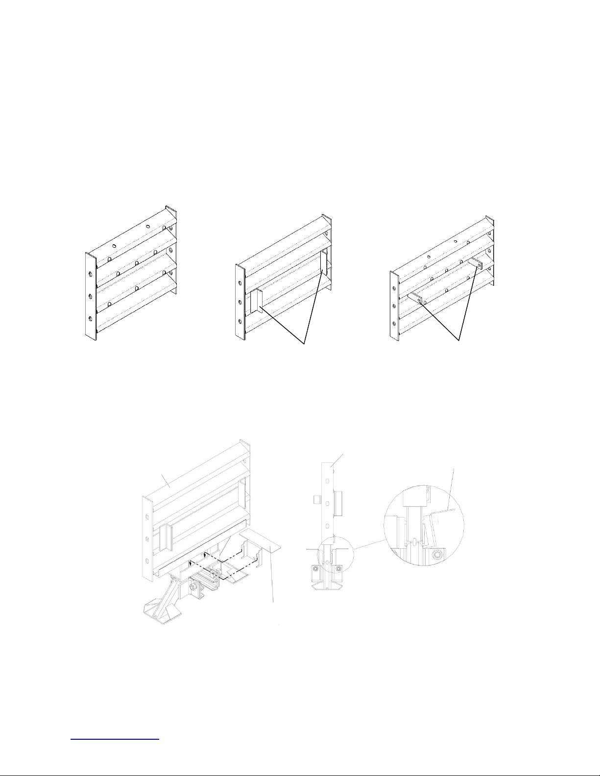
9) Attach Cartridge Support Brackets (Figure 32)
g
y
Attach lower Cartridge Support Bracket to front and back of all Diaphragms and front of
Backup, as shown in Figures 32 to 35 and Backup Assembly drawings.
Note: 24” [610 mm] wide systems do not have Side Cartridge Support Brackets: 30” [760 mm],
36” [915 mm] and 48” [1219 mm] wide systems have Side Cartridge Support Brackets welded to
the Backup and Diaphragms.
24” [610 mm] WIDE
30” DIAPHRAGM
30” [762 mm] WIDE
36” [915 mm] WIDE
SIDE CARTRIDGE
SUPPORT BRACKETS
SIDE CARTRIDGE
SUPPORT BRACKETS
Figure 32
Side Cartridge Support Brackets
DIAPHRAGM
CARTRIDGE
SUPPORT BRACKET
CARTRIDGE SUPPORT BRACKET
Figure 33
Lower Cartrid
e Support Bracket Assembl
trinityhighway.com 34 Revision D September 2019
Page 36
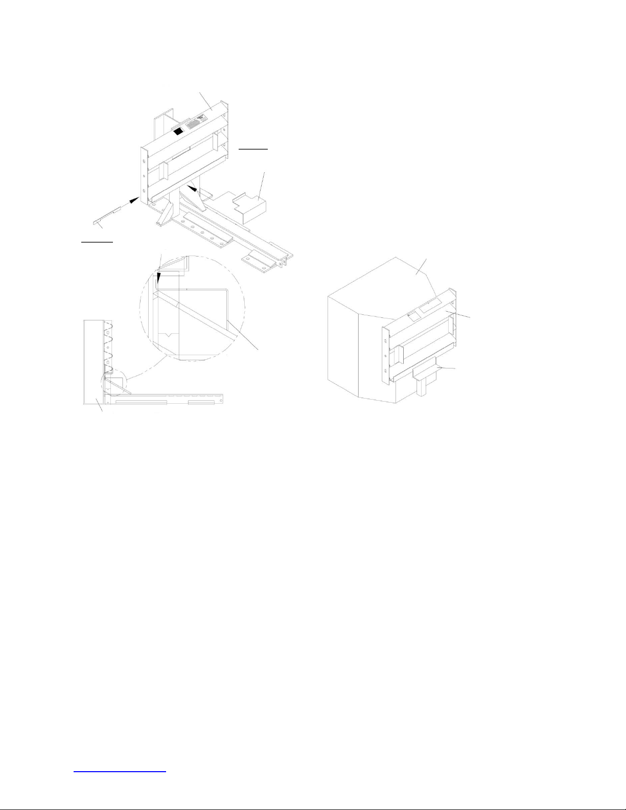
TENSION STRUT BACKUP [30” shown]
STEP II
MOUNT LOCKING BAR
STEP I
MOUNT CARTRIDGE
SUPPORT BRACKET
CONCRETE BACKUP
FACE PLATE
CARTRIDGE
SUPPORT BRACKET
TENSION STRUT BACKUP
Lower Cartridge Support Bracket Assembly
(Tension Strut Backup)
Figure 34
Lower Cartridge Support Bracket
CARTRIDGE
SUPPORT BRACKET
CARTRIDGE SUPPORT
BRACKET IS WELDED TO FACE
PLATE OF CONCRETE BACKUP
Figure 35
(Concrete Backup)
trinityhighway.com 35 Revision D September 2019
Page 37
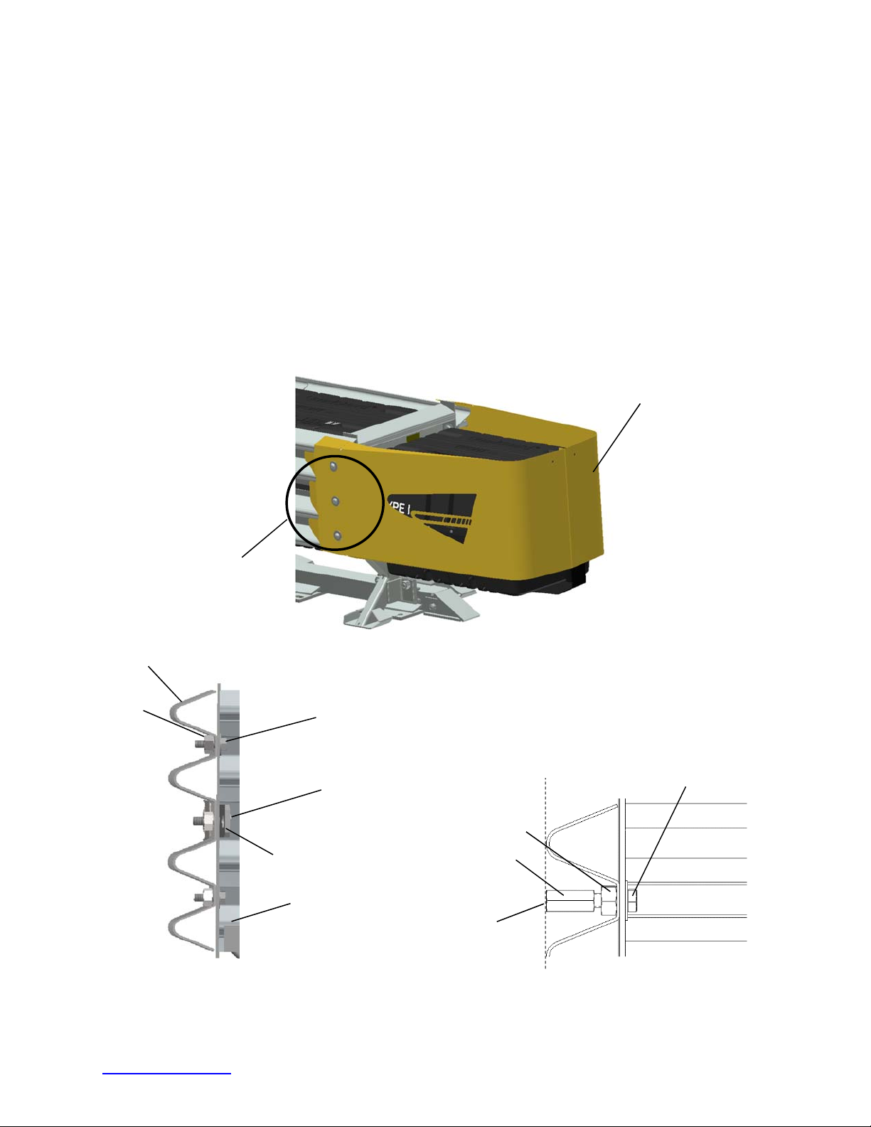
10) Attach Steel Nose Assembly
V
A
U
A) Install two (2) 5/8” X 2” hex bolts and one (1) 5/8 X 2 1/2” hex bolt with Pullout Bracket
through Diaphragm side plate. Fasten all three (6 total) bolts with 5/8” rail nuts on each
side and tighten (Detail 36A).
B) Thread 5/8” coupling nuts on 5/8” hex bolts to align with outside of Fender Panel (Detail
36B).
C) Join Steel Nose halves using 1/4” X 3/4” hex bolts, lock washers and nuts. Include
Cartridge Support Nose Bracket in lower two fastener sets (Detail C & D).
D) Attach Steel Nose to Diaphragm using 5/8” X 1 1/4” hex socket bolt and 5/8” x 1 1/4” flat
washer (Detail 69E). Steel Nose top edge should be 32 1/8” above concrete surface.
E) Place the Cartridge Support Bracket on the front of the first Diaphragm (Detail 36F).
Place a Type I Cartridge in the Nose Bay.
STEEL NOSE ASSEMBLY
IEWS 36A - F
FENDER PANEL
RAIL
N
T
Figure 36
5/8” X 2”
HEX BOLT
5/8” X 2 1/2” HEX BOLT
5/8” RAIL NUT
PULLOUT
BRACKET
DIAPHRAGM
5/8” COUPLING NUT
LIGN END OF
COUPLING NUT WITH
OUTSIDE HUMPS OF
FENDER PANEL
5/8” X 2”
HEX BOLT
Detail 36A
Fastener Assembly
End View: Nose Cover Cut Away
trinityhighway.com 36 Revision D September 2019
Detail 36B
Page 38
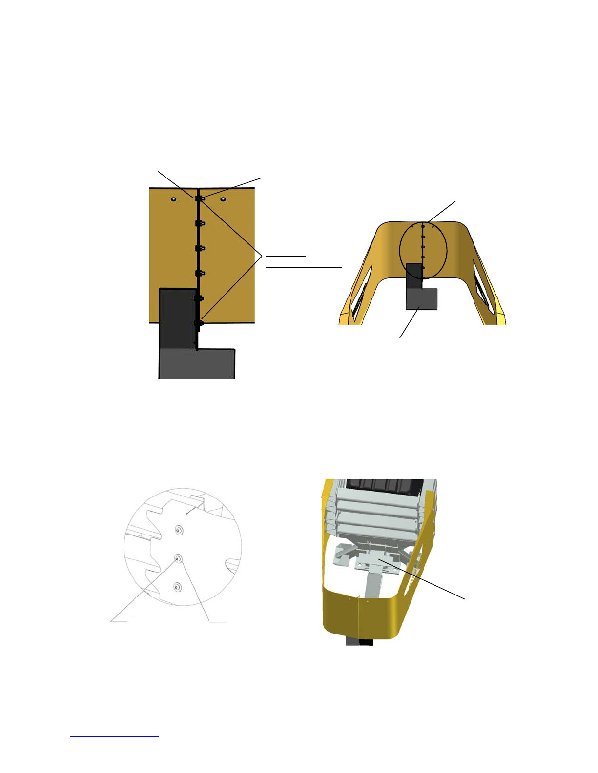
HEX BOLT 1/4 X 3/4
Detail 36C
LOCK WASHER 1/4”
HEX NUT 1/4”
Detail 36C
Total Six
1/4-20 Fasteners
Nose Cartridge
Support Bracket
Detail 36D
5/8” X 1 1/4"
HEX SOCKET
BUTTON BOLT
5/8” FLAT
WASHER
Note height of Nose Cartridge
Support Bracket. The Cartridge
sits 2” lower on this Bracket
than other Bays toward the rear.
Detail 36E
Detail 36F
Detail 36D shows proper placement of front Cartridge Support Bracket.
trinityhighway.com 37 Revision D September 2019
Page 39
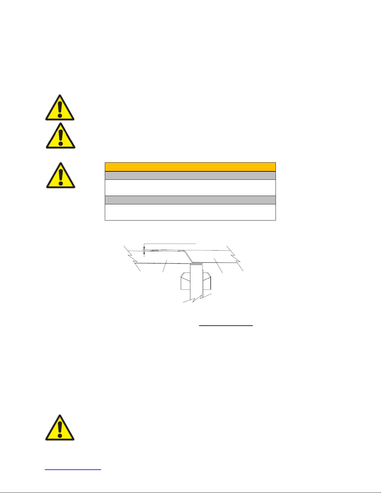
11) Checking the System Assembly
Recheck to ensure that all fasteners are properly tightened throughout the system (anchor
bolts, etc.). See torque requirements below. Check all Fender Panels. If they do not fit tightly
against the underlying Fender Panel, system realignment may be necessary (Figure 37).
Verify the top of the Steel Nose is 32 1/8” above the roadway (p. 36).
Warning:
Ensure that the QuadGuard® II and delineation used meet all federal,
state, specifying agency, and local specifications.
Warning:
Ensure delineation on the assembly meets all ap propriate MUTCD and
local standards.
Warning:
Anchor Requirements
Anchor Studs – Anchoring Information Table, p. 16
May slightly protrude above nuts
Critical Clearances
Anchor Studs above nuts – Figure 21, p. 27
Fender Panel Gap Narrow – 7/8” [22 mm] see below
MAXIMIM GAP = 7/8” [22 mm]
UNDERLYING FENDER, TRANSITION,
EXTENTION OR SIDE PANEL
FENDER PANEL
Figure 37
Fender Panel Gap for Narrow Systems
13) Cartridge Placement
Be sure the Adjustable Cartridge Support in the Nose is attached correctly (p. 37). The top
surface of the Nose Cartridge should be horizontal.
®
To complete the assembly of a QuadGuard
II, place the appropriate Cartridge in each Bay
and Nose section of the system. Type 1 Cartridges are placed toward the front (Nose) of
the system; Type 2 Cartridges are placed toward the rear (Backup) of the system (Figures
38 and 39). Ensure all Cartridges are pointed toward the front of the system per Cartridge
direction arrow(s).
Warning:
Placing the wrong Cartridge in the Nose or any Bay will result in system
performance that has not been crash tested pursuant to the NCHRP Report 350
criteria.
trinityhighway.com 38 Revision D September 2019
Page 40
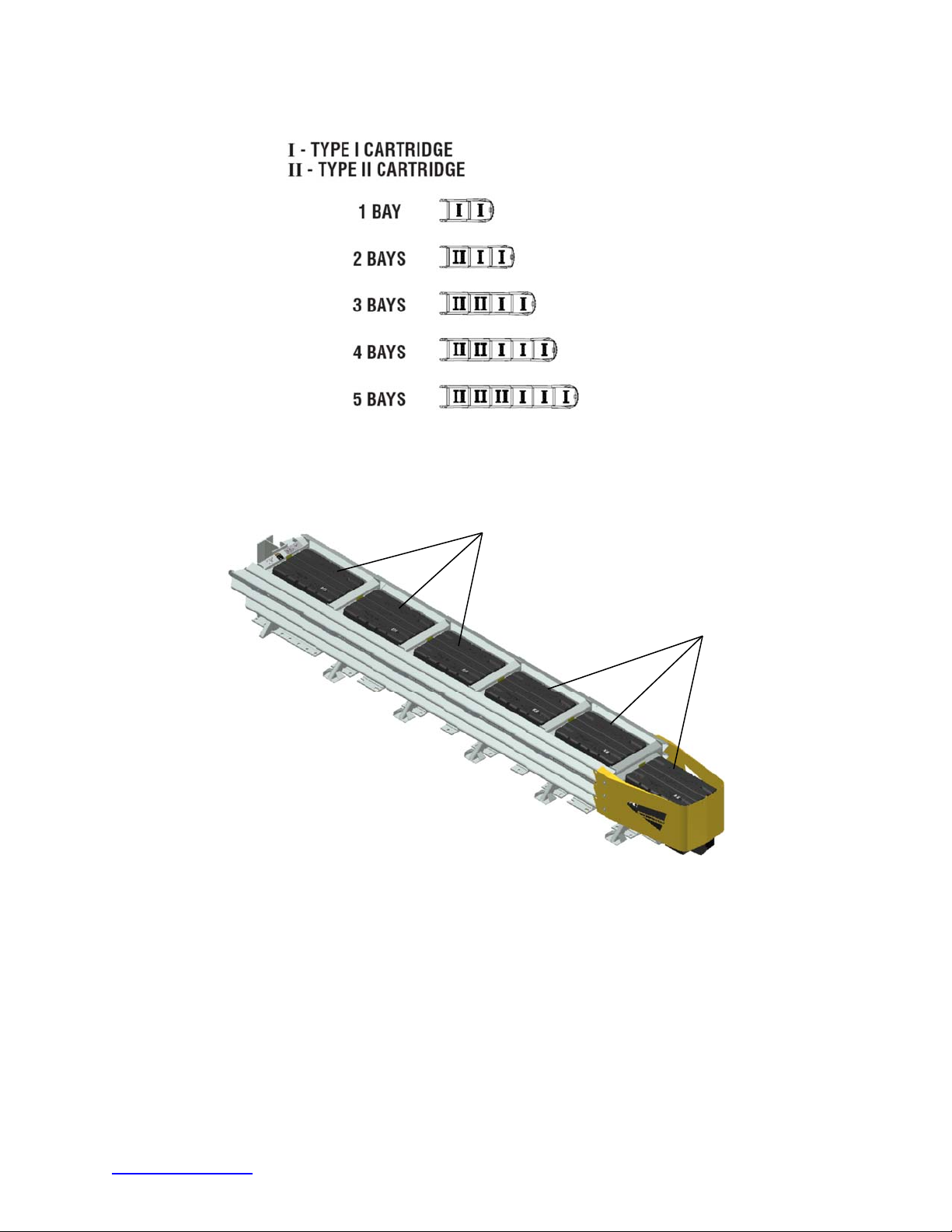
Figure 38
Cartridge Placement
Type 2
Figure 39
Five Bay System
Type 1
trinityhighway.com 39 Revision D September 2019
Page 41
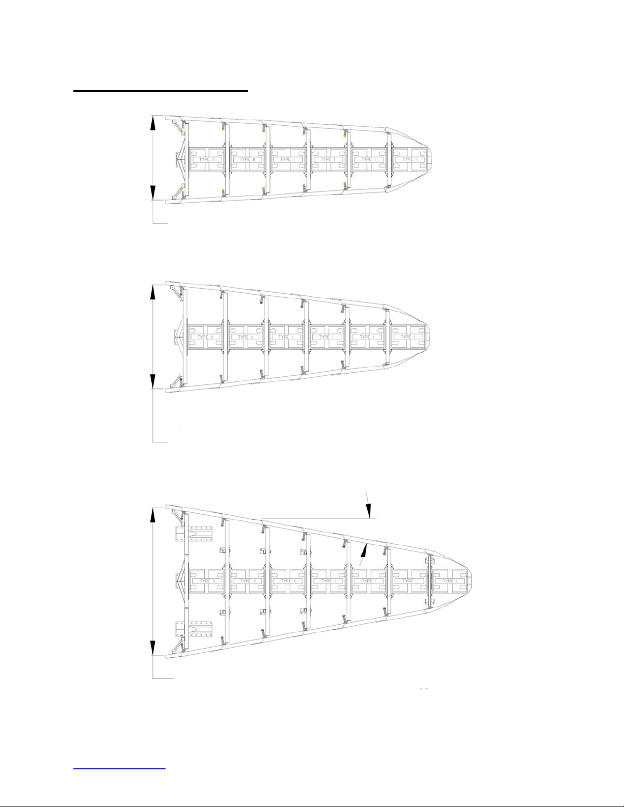
Wide (Flared) Systems
[
(Min. 3 Bays)
1755 mm [69”] Model No. QG2 _ _ 69
(Min. 3 Bays)
2285 mm [90”] Model No. QG2 _ _ 90
Varies - (Min. 6 Bays)
3200 mm
126”] Model No. QG2 _ _ 126
Figure 40
Wide System(s) and Model Numbers
10 Deg.
trinityhighway.com 40 Revision D September 2019
Page 42
Assemble Wide (Flared)
Important:
The Manufacturer’s Drawing Package supplied with the QuadGuard®
II must be used with these instructions for proper assembly and should take
precedence over these general instructions.
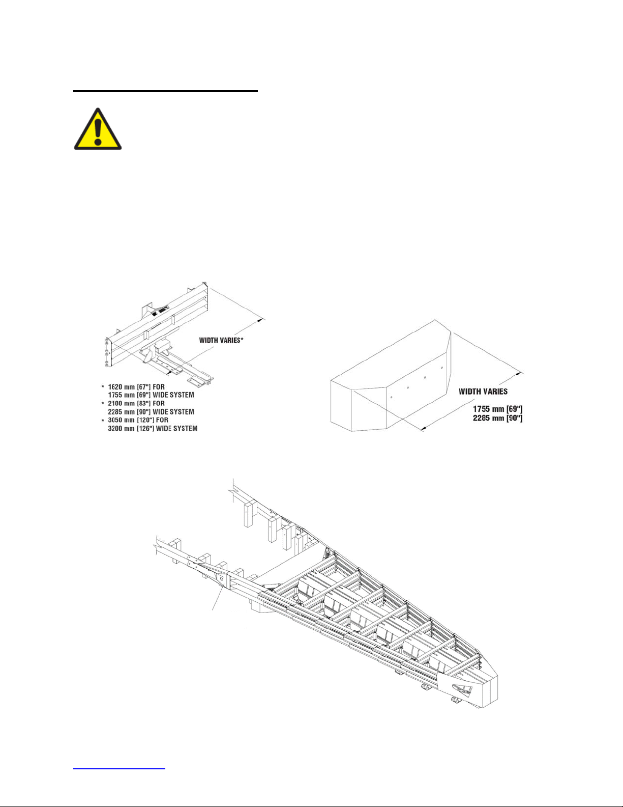
Determine Backup and Transition Type
The QuadGuard® II is available with a Tension Strut Backup or a Concrete Backup. See
Figures 41 and 42, along with the Backup assembly drawing, to determine which type of
Backup is being deployed.
A Transition Panel or Side Panel must be used on each side of the Backup. A Side Panel
is not needed when a Transition Panel is used. Several types of transitions are available for
use with the QuadGuard
Package to determine which types of Fender Panels to attach.
®
II. See Figures 44 through 48 and the Manufacturer’s Drawing
Tension Strut Backup
Figure 41
QUAD-BEAM TO W-BEAM
TRANSITION PANEL
Figure 42
Concrete Backup
Figure 43
QuadGuard
®
II Transitioning
trinityhighway.com 41 Revision D September 2019
Page 43
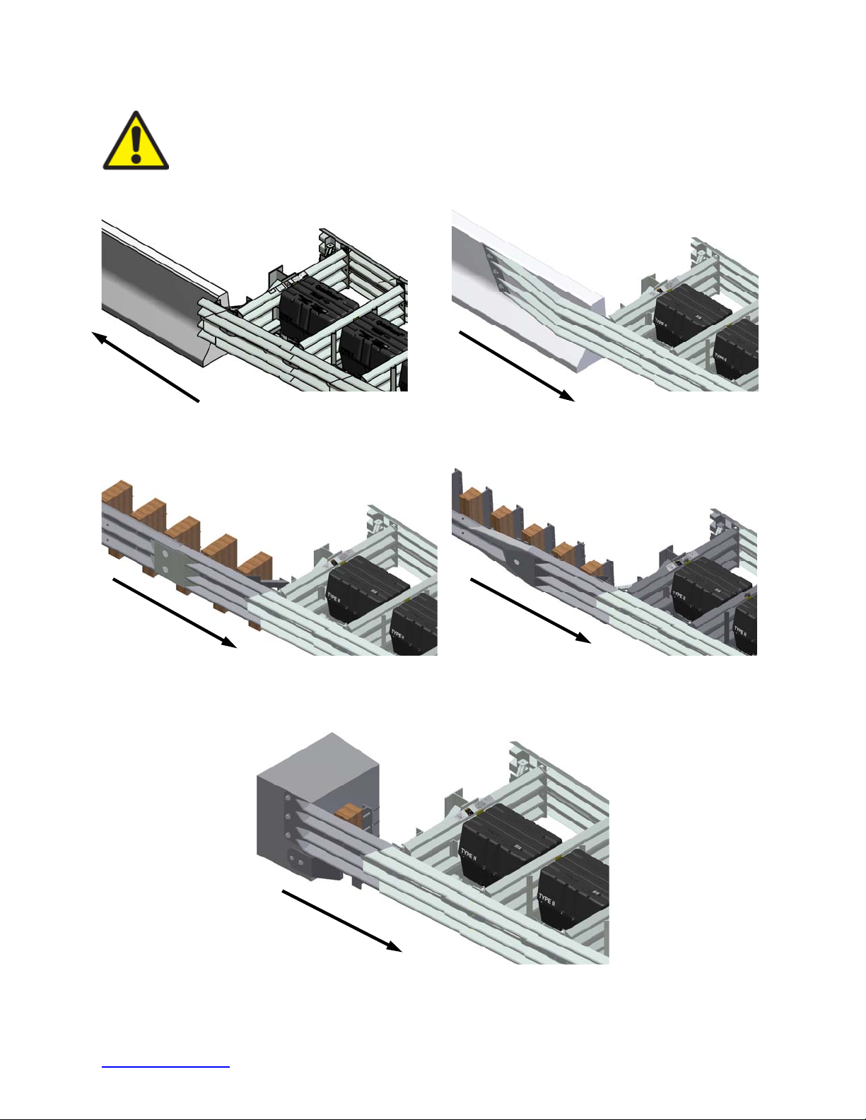
Important:
The proper Transition Panel or Side Panel must be used to perform
as crash tested. The correct Panel(s) to use will depend on the direction of
®
traffic and what type of barrier or roadside obstacle the QuadGuard
II is
shielding. Contact Customer Service prior to deployment if you have any
questions (p. 3).
Figure 44
No Transition
Note: Arrows indicate traffic direction.
Figure 46
Quad-Beam to Thrie-Beam
Figure 45
Quad-Beam to Safety Shape Barrier
Figure 47
Quad-Beam to W-Beam
Note: Arrows indicate traffic direction.
Figure 48
Quad-Beam End Shoe
trinityhighway.com 42 Revision D September 2019
Page 44
1) Mark System Location
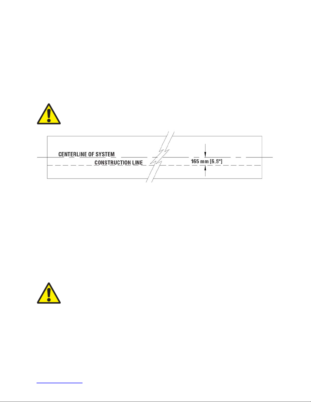
Locate the centerline of the system by measuring the proper offset from the roadside obstacle.
See the Manufacturer’s Drawing Package supplied with the system. Place chalk line to mark
the centerline of the system. Mark a construction line parallel to the center line and offset
6.5” [165 mm] to one side as shown in Figure 49. The edge of the Monorail will be placed on
this line.
Note:
The concrete foundation shall comply with the Manufacturer’s Drawing Package supplied
with the system.
Warning:
Location of system with respect to the roadside object is critical and
dependent on the type of Transition Panel used. See the Manufacturer’s Drawing
Package supplied with the system for details.
(Top view of concrete foundation)
Figure 49
2) Anchor the Backup
A) Concrete Backup Construction (Figure 50)
Locate Backup Face Plate using the Backup assembly drawing. Verify that any applicable
Transition Panels fit properly before anchoring the Face Plate. Drill anchor boreholes
in the Concrete Backup using the Face Plate as a template. Anchor the Face Plate to the
®
Concrete Backup using an approved adhesive supplied with the QuadGuard
II (p. 16).
A Trinity Highway approved adhesive anchoring system is required to securely anchor
crash cushions and other common highway devices. Trinity Highway approved adhesive
features high pullout strength, vibration resistance, and durability. Each approved adhesive
kit contains adhesive, studs, nuts and washers. Both vertical and horizontal assemblies
require an approved adhesive anchoring system.
Warning:
Every borehole and slot in Backup and Monorail must be anchored by
a stud using an approved adhesive.
B) Tension Strut Backup Assembly (Figure 51)
Locate the Tension Strut Backup and Monorail on foundation with side of Monorail on the
construction line (p. 47). Verify that any applicable Transition Panels fit properly
before anchoring Backup. Drill 7/8” [22 mm] diameter by 5 3/4” [145 mm] deep anchor
boreholes in foundation using the Backup as template. Anchor the Backup to the concrete
foundation using the Trinity Highway approved adhesive supplied with the QuadGuard
®
(p. 16).
trinityhighway.com 43 Revision D September 2019
II
Page 45
A
FULLY CURED CONCRETE BACKUP
(SEE MANUFACTURER’S DRAWING
PACKAGE)
APPROVED ADHESIVE
WITH 3/4" X 6 1/2” STUD
BACKUP FACE PLATE
Figure 50
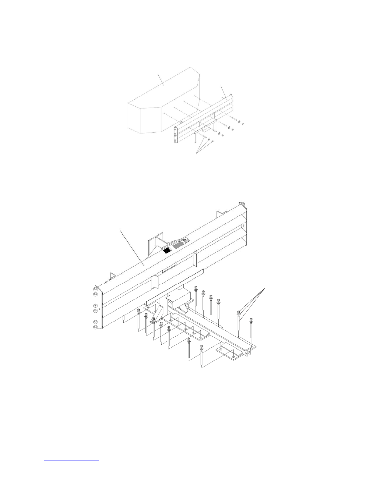
Anchoring Backup Face Plate to Concrete Backup
TENSION STRUT BACKUP
Anchoring Tension Strut Backup to Foundation
Figure 51
PPROVED ADHESIVE
WITH 3/4" X 7” STUD
trinityhighway.com 44 Revision D September 2019
Page 46
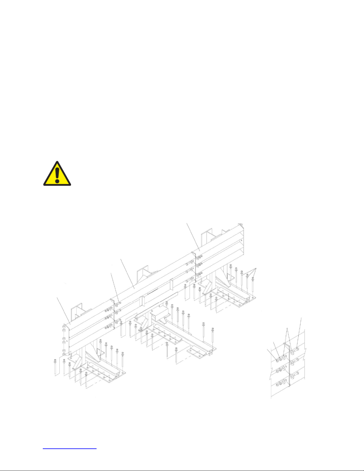
C) Extra-Wide Tension Strut Backup Assembly (Figure 52)
A
A
A
A
Locate the Extra-Wide Tension Strut Backup center section and Monorail on foundation
with side of Monorail on the construction line.
Locate the Extra-Wide Tension Strut Backup left section on the left side of the center
section, aligning the three holes in the side plates.
Locate the Extra-Wide Tension Strut Backup right section on the right side of the center
section, aligning the three holes in the side plates.
Secure the Backup sections to each other using 5/8” x 2” hex bolt, 5/8” x 1 3/4" flat washer
(2), 5/8” lock washer and 5/8” hex nut (6 places) as shown in Figure 52 and Detail 52a.
Verify that any applicable Transition Panels fit properly before anchoring Backup.
Drill anchor boreholes in foundation using the Backup as template. Anchor the Backup to
the foundation using Trinity Highway approved adhesive kits supplied with the
®
QuadGuard
II (p. 16).
Warning: Every borehole and slot in Backup and Monorail must be anchored by
a stud using a Trinity Highway approved adhesive.
-WIDE
EXTR
TENSION STRUT BACKUP
RIGHT SECTION
EXTR
-WIDE
TENSION STRUT BACKUP
CENTER SECTION
DETAIL 52a
-WIDE
EXTR
TENSION STRUT BACKUP
LEFT SECTION
Figure 52
Anchoring Extra-Wide Tension Strut Backup to Foundation
PPROVED ADHESIVE
WITH 3/4" X 7” STUD
5/8” X 2” HEX BOLT
5/8” X 1 3/4” FLAT WASHER
5/8” LOCK WASHER
5/8” HEX NUT
Detail 52a
trinityhighway.com 45 Revision D September 2019
Page 47
3) Anchor the Monorail
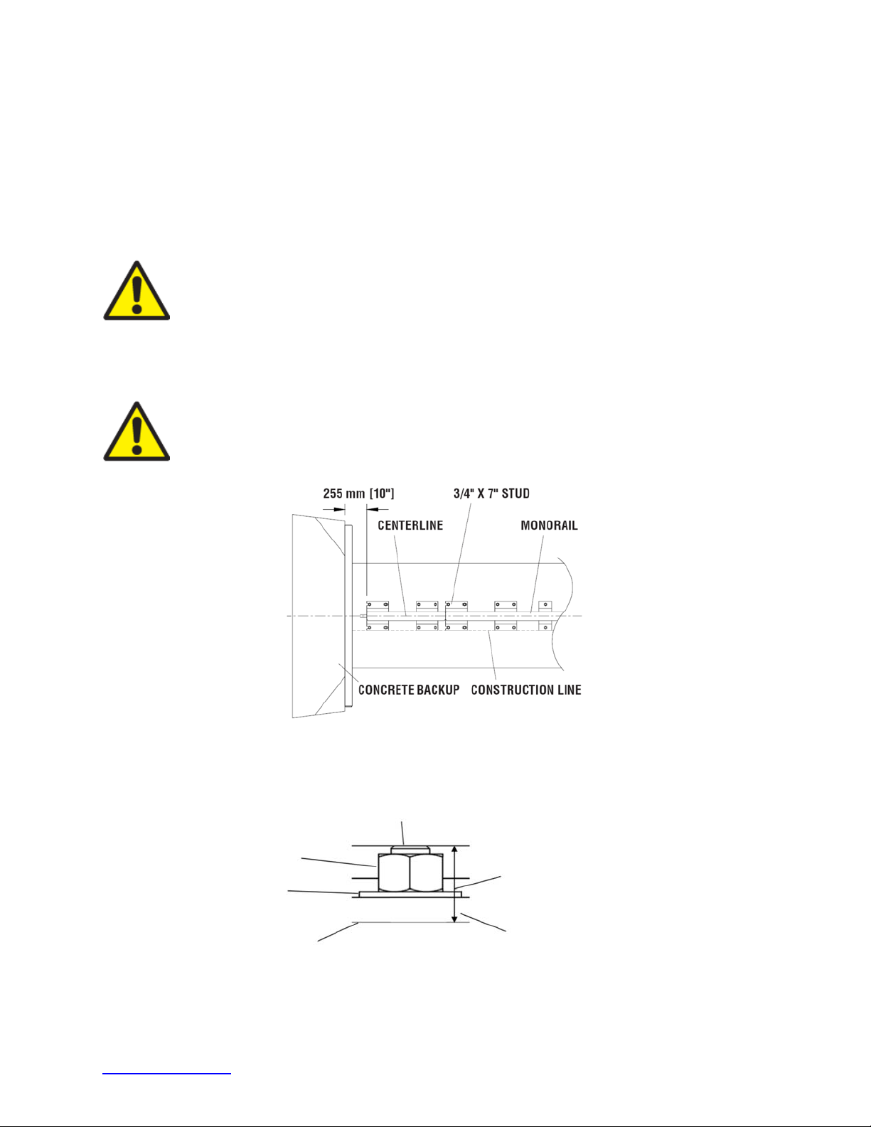
A) Monorail Placement for Concrete Backup (Figure 53)
Locate Monorail on foundation with side of Monorail on the construction line and rear edge of
Monorail 10” forward of front face of Concrete Backup. Orient the Monorail so that the Monorail
tongues face Backup (Figure 53).
Drill 7/8” [22 mm] diameter by 5 3/4” [145 mm] deep boreholes using the Monorail as a
template. Do not drill through foundation.
Warning:
Improper alignment at the Monorail Splice Joints may prevent proper
system collapse during impact (Figure 56).
Anchor each Monorail section using an approved adhesive kit (p. 16). It is important to attach
each segment of Monorail in alignment from the back to the front of the system
(±1/4” [6 mm]).
Warning:
Every borehole and slot in Backup and Monorail must be anchored by
a stud using an approved adhesive.
Monorail Placement for Concrete Backup
Figure 53
ANCHOR
NUT
WASHER
ROADWAY
CAUTION:
40 mm [1.5”]
MAXIMUM STUD HEIGHT
BACKUP OR MONORAIL
Figure 54
Proper Stud Height
trinityhighway.com 46 Revision D September 2019
Page 48
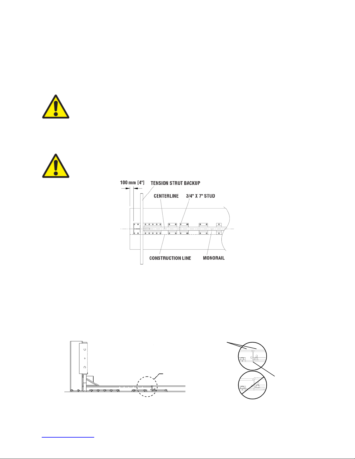
Monorail Placement for Tension Strut Backup (Figure 55)
Locate Monorail on foundation with side of Monorail on the construction line and rear edge of
Backup 4” forward of edge of foundation. Orient the Monorail so that the Monorail tongues
face the Backup (Figure 56 & Detail 56a).
Drill 7/8” [22 mm] diameter by 5 3/4” [145 mm] deep boreholes using the Monorail as a
template. Do not drill through foundation.
Warning:
Every borehole and slot in Backup and Monorail must be anchored by
a stud using an approved adhesive.
Anchor each Monorail section using the Trinity Highway approved adhesive kits provided.
See Figure 54 and the approved adhesive instructions included with each kit. It is important
to attach each segment of Monorail in alignment from the back to the front of the system
(±1/4” [6 mm]).
Warning:
Improper alignment at the Monorail splice joints will prevent proper
system collapse during an impact (Figure 56).
Figure 55
Backup and Monorail Placement for Tension Strut Backup
It is important to align each segment of Monorail from the back to the front of the system
(±1/4” [6 mm]). Anchor each Monorail section using the provided Trinity Highway approved
adhesive kit.
Drill 7/8” [22 mm] diameter by 5 3/4” [145 mm] deep boreholes using the Monorail as a
template. Do not drill through foundation.
Top surfaces
must be flush
Tongues must be
Detail 56a
Fully Inserted
and Flush
Figure 56
Rail Height and Alignment
trinityhighway.com 47 Revision D September 2019
Page 49
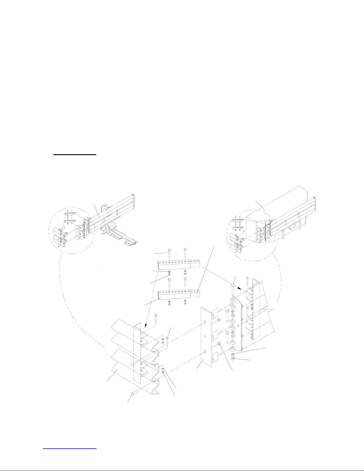
4) Attach Side Panels and/or Transition Panels to Backup Assembly (Figure 57)
/
/
a. Attach Hinge Plate to the Transition Panel or Side Panel using 5/8” rail bolt and 5/8”
rail nut (two places – top and bottom holes only).
b. Attach Transition Panel or Side Panel assembly to Backup using 5/8” hex bolt, 5/8”
lock washer and 5/8” hex nut (three places each side of Backup).
c. Attach diagonal brace to Fender Panel and Backup using 3/8” hex bolt, 3/8” lock
washer and 3/8” hex nut (two (2) places per brace: four (4) places per side).
d. Secure each diagonal brace with a 3/8” hex bolt; 3/8” lock washer, and 3/8” hex nut
(two (2) places per brace) as shown in Figure 57.
Note:
A Side Panel is not needed when a Transition Panel is used. Diagonal braces are not
used with some Transition Panels per the Manufacturer’s Drawing Package.
Assembly tip:
Use drift pin to align the center hole of the Panel with the center hole of the Backup before
attaching the rail bolts.
TENSION STRUT BACKUP
DIAGONAL BRACE (INNER)
3/8” X 3 1/2" HEX BOLT
3/8” LOCK WASHER
3/8” HEX NUT
DIAGONAL BRACE (OUTER)
CONCRETE BACKUP
5
8” X 4" HEX BOLT
3/8” X 3 1/2"
HEX BOLT
5/8” LOCK WASHER
8” HEX NUT (SMALL)
5
HINGE PLATE
WIDE SIDE PANEL
3/8” LOCK WASHER
3/8” HEX NUT
5/8” RAIL BOLT
Figure 57
Side Panel/Transition Panel Attachment
trinityhighway.com 48 Revision D September 2019
5/8” RAIL NUT (LARGE)
Page 50
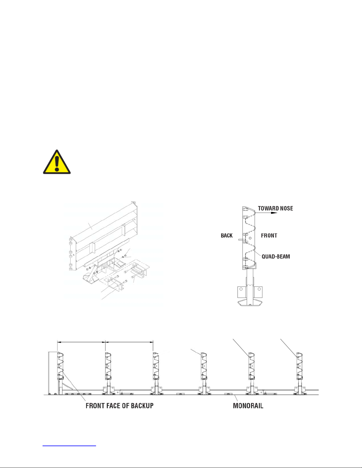
5) Attach Monorail Guides
Attach Monorail guides to Diaphragm as follows:
Insert 3/4” x 2” G8 hex bolt through Monorail guide and Diaphragm (Figure 58). Check
orientation and secure hex bolt with 3/4” lock washer and 3/4” hex nut (typical two places per
guide). See also Diaphragm assembly drawing. Shims are sandwiched between Monorail
guides and Diaphragm.
Repeat process for each Diaphragm.
6) Attach Diaphragms
Orient the widest Diaphragm so that the front face of the Diaphragm shape faces toward the
Nose of the system as shown in Figure 59. The widest Diaphragm must be attached
closest to the Backup with each subsequent Diaphragm being progressively narrower.
Important:
Slide the widest Diaphragm onto the Monorail and all the way to the
Backup to ensure system is able to collapse properly during impact. Once this has
been verified, slide the Diaphragm forward to approximately 36” [915 mm] in front
of the Backup.
Orient and slide all other Diaphragms onto Monorail and position each approximately as
shown in Figure 60.
DIAPHRAGM
MONORAIL GUIDE
Monorail Guide Attachment
915 mm [36”]
SHIM
Figure 58
915 mm [36”]
3/4” HEX NUT
3/4” LOCK WASHER
3/4” X 2 G8 HEX BOLT
Bay 3 & Higher
rd
Diaphragm
3
Figure 59
Diaphragm Orientation
nd
Diaphragm
2
st
Diaphragm
1
Bay 2Bay 3 Bay 1 Nose
Figure 60
Diaphragm spacing
trinityhighway.com 49 Revision D September 2019
Page 51
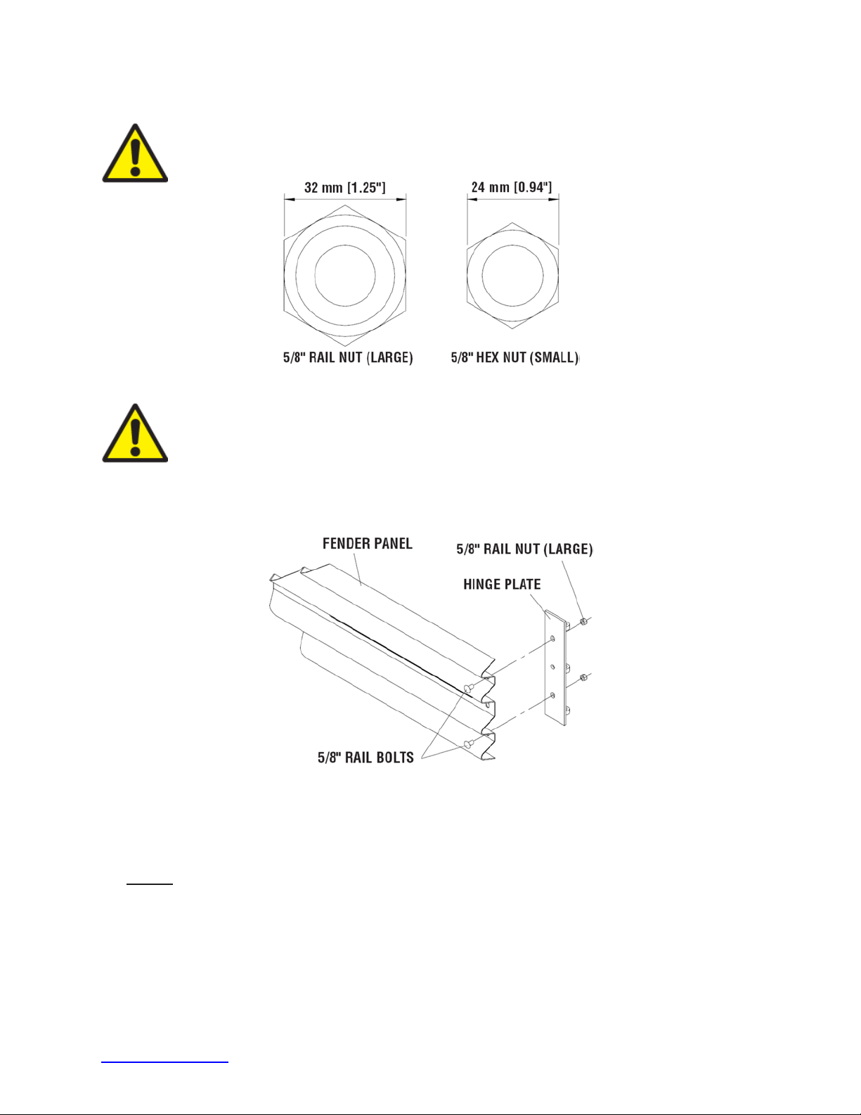
7) Attach Hinge Plate onto Fender Panels
Important:
Important:
Plates.
Attach Hinge Plate on each Fender Panel using two (2) 5/8” rail bolts and two (2) 5/8” rail nuts,
using top and bottom holes only, leaving the center-hole open as shown in Figure 62.
Do not mix the 5/8” rail nuts (large) with the 5/8” hex nuts (small).
Figure 61
Rail Nuts are Oversize
For proper impact performance, wide systems must use Hinge
Figure 62
Hinge Plate Assembly
8) Attach Fender Panels
Starting at the Backup, attach left and right Fender Panels as shown in Figure 63.
Step 1
Place the Fender Panel so that the center of the slot of the rearward Diaphragm is lined
up with the approximate center of the slot in the Fender Panel.
Install the Mushroom Washer Assembly as shown in Figure 63 and Detail 63A, but do not
torque at this time (this will help to balance the Fender Panel).
trinityhighway.com 50 Revision D September 2019
Page 52
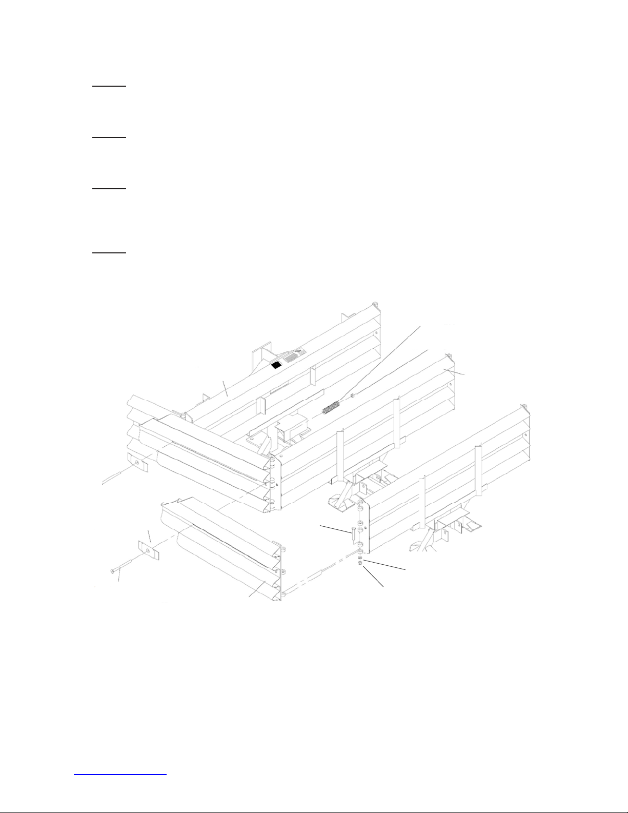
Step 2
Slide the Fender Panel forward until the holes in the Fender Panel line up with the holes
in the forward Diaphragm.
Step 3
Use a drift pin to align the center hole of the Fender Panel with the center hole of the
Diaphragm.
Step 4
Attach the front of the Fender Panels to the next Diaphragm using two (2) rail bolts and
large rail nuts per side. Use only the top and bottom holes; leave the center hole open
until the next Fender Panel is attached.
Step 5
Be sure Mushroom Washer lays flat against the Fender Panel as shown in Figure 63B.
Standoff on Mushroom Washer must be seated completely through slot.
MUSHROOM WASHER
5/8” X 8 1/2”, G8
FLATHEAD SOCKET SCREW
BACKUP
FENDER PANEL
5/8” X 4” G5 HEX BOLT
6” DIE SPRING
5/8” RAIL NUT (LARGE)
5/8” LOCK WASHER
5/8” HEX NUT (SMALL)
LAST DIAPHRAGM
Figure 63
Wide Fender Panel Assembly
trinityhighway.com 51 Revision D September 2019
Page 53
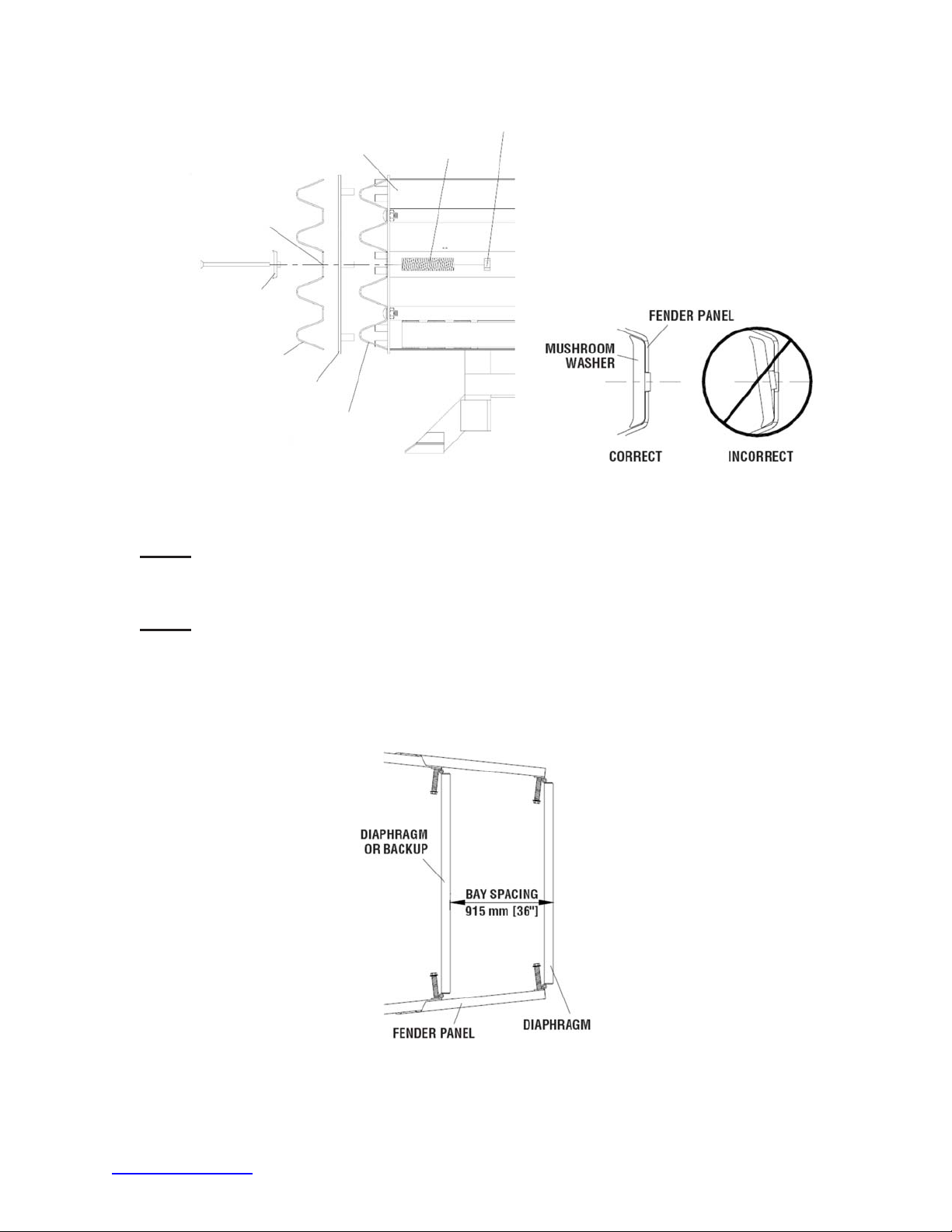
LONG SLOT IN
FENDER PANEL
DIAPHRAGM
OR BACKUP
5/8” RAIL NUT (LARGE)
6” DIE SPRING
MUSHROOM WASHER
QUAD-BEAM
FENDER PANEL
HINGE PLATE
PANEL ALREADY ATTACHED
TO DIAPHRAGM OR BACKUP
Mushroom Washer Attachment
Step 6
Check Diaphragm spacing to ensure 36” [915 mm] between rear faces of consecutive
Diaphragms as shown in Figure 64 and Fender Panel Assembly drawing.
Step 7
Once the proper spacing has been achieved, tighten the Mushroom Washer Assembly
(large rail nut) until it reaches the end of the threads. Assemble the remaining Diaphragms
and Fender Panels following the same procedures. Tighten rail nut (large hex) at the front
of the Fender Panels. Ensure the rail bolt shoulder is seated within the Fender Panel slot.
Figure 63A
Figure 63B
Mushroom Washer Orientation
Figure 64
Proper Diaphragm Spacing
trinityhighway.com 52 Revision D September 2019
Page 54
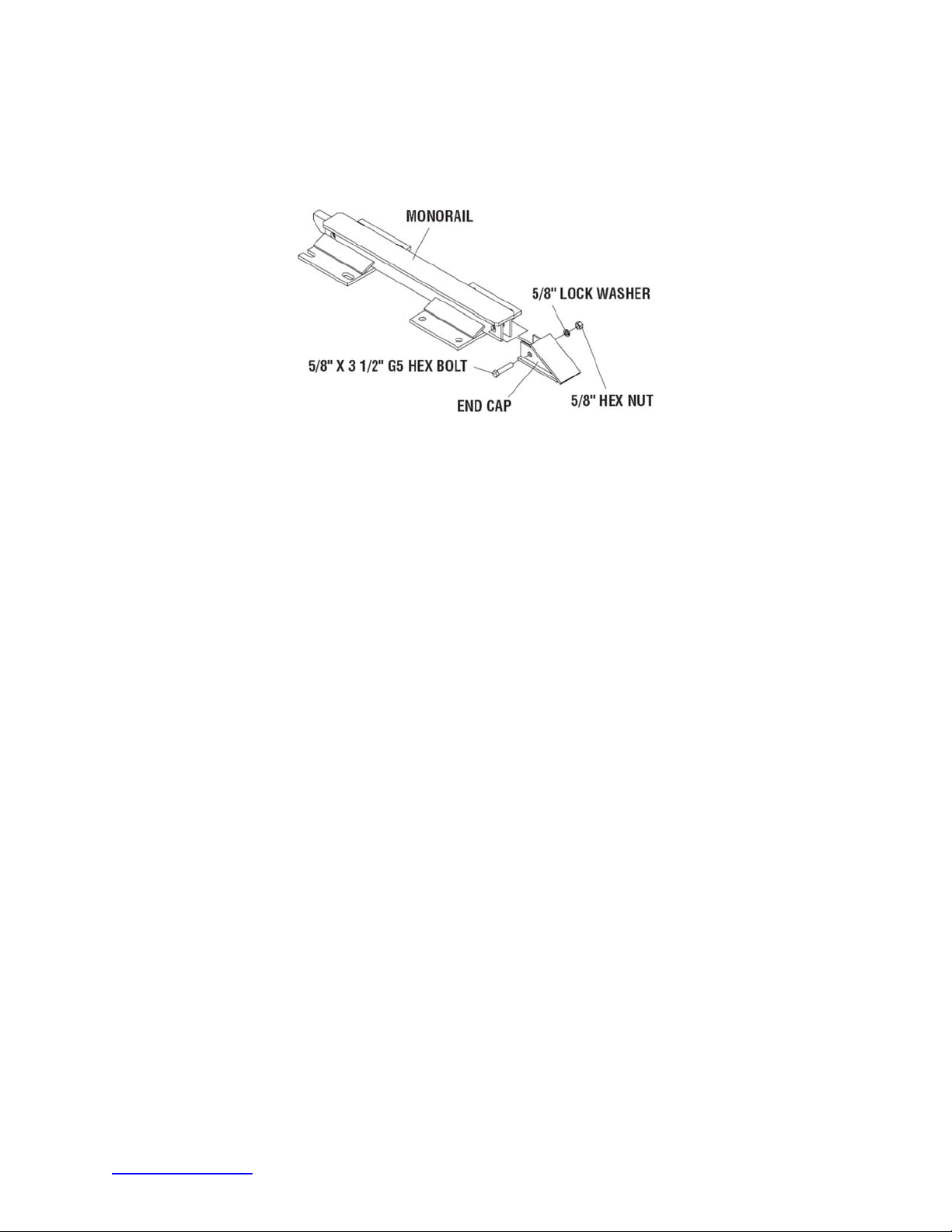
9) Attach End Cap
Using 5/8” x 3 1/2” G5 hex bolt, 5/8” hex nut and 5/8” lock washer, attach the End Cap to the
front of the first Monorail segment.
Figure 65
Monorail End Cap Assembly
trinityhighway.com 53 Revision D September 2019
Page 55
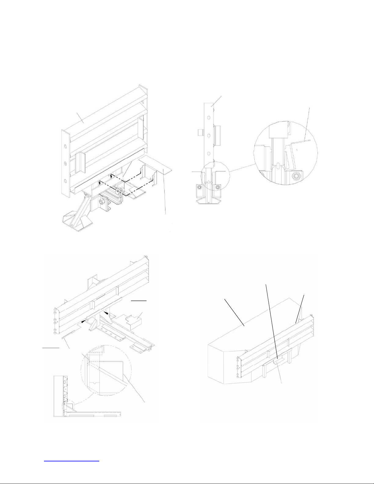
10) Attach Cartridge Support Brackets
Attach Cartridge Support Bracket to all Diaphragms and Backup as shown in Figures 66 - 69,
the Backup Assembly drawing, and the Diaphragm Assembly drawing.
DIAPHRAGM
CARTRIDGE
DIAPHRAGM
CARTRIDGE SUPPORT BRACKET
SUPPORT BRACKET
STEP II
ATTACH “KEEPER”
Figure 66
Diaphragm with
Cartridge Support Bracket
STEP I
ATTACH CARTRIDGE
SUPPORT BRACKET
CARTRIDGE SUPPORT BRACKET
CARTRIDGE SUPPORT BRACKET
CONCRETE BACKUP
CARTRIDGE SUPPORT BRACKET
IS WELDED TO THE FACE PLATE
FACE PLATE
Cartridge Support Bracket
Figure 67
Cartridge Support Bracket
(Tension Strut Backup)
Figure 68
(Concrete Backup)
trinityhighway.com 54 Revision D September 2019
Page 56
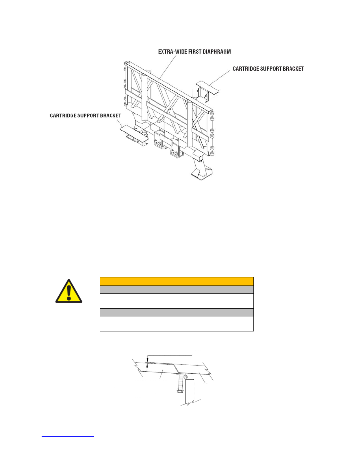
Extra-Wide First Diaphragm with Cartridge Support Bracket
11) Attach Nose Assembly
Figure 69
(See Drawing Package)
See pages 36 and 37 for Nose Assembly instructions.
12) Checking the System Assembly
Recheck to ensure that all fasteners are properly tightened throughout the system (anchor
bolts, etc.). Review torque requirements below and inspect all Fender Panels. If they do not
fit tightly against the underlying Fender Panels, system realignment may be necessary
(Figure 70). Verify top of Steel Nose height is 32 1/8” above the roadway (p. 36).
Warning:
Anchor Studs – Anchoring Information Table, p. 16
May slightly protrude above nuts
Anchor Studs above nuts – p. 46, Figure 54
Fender Panel Gap Wide – 1.00” [25 mm] see below
UNDERLYING FENDER, TRANSITION,
EXTENTION OR SIDE PANEL
Anchor Requirements
Critical Clearances
MAXIMIM GAP = 1.00” [25 mm]
FENDER PANEL
Figure 70
Fender Panel Gap for Wide Systems
trinityhighway.com 55 Revision D September 2019
Page 57
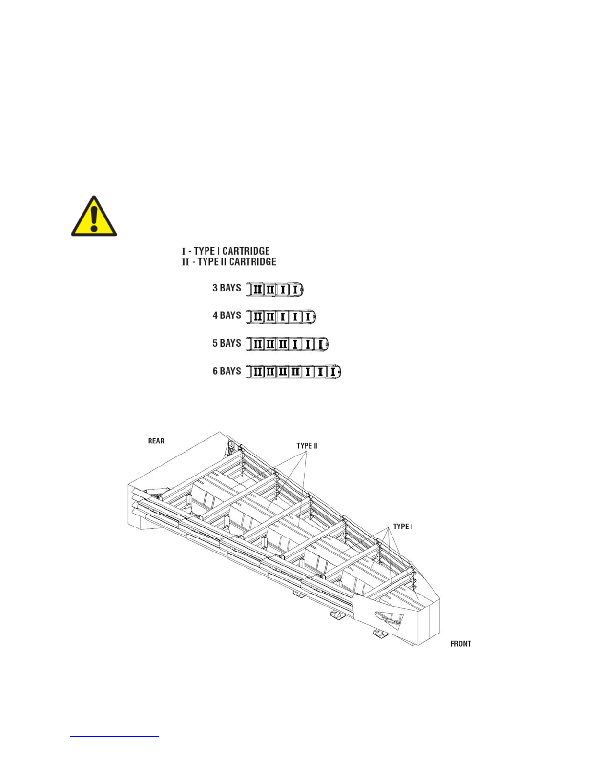
13) Cartridge Placement
Ensure the Adjustable Cartridge Support in the Nose is attached correctly (p. 36). The top
surface of the Nose Cartridge should be horizontal.
®
To complete the assembly of a QuadGuard
II, place the appropriate Cartridge in each Bay
and Nose section of the system. Type I Cartridges are placed toward the front (Nose) of the
system; Type II Cartridges are placed toward the rear (Backup) of the system (Figures 71 and
72). Ensure all Cartridges are pointed toward the front of the system per Cartridge direction
arrow.
Warning:
Placing the wrong Cartridge in the Nose or any Bay will result in system
performance that has not been crash tested pursuant to the NCHRP Report 350
criteria.
Figure 71
Cartridge Placement
Figure 72
Five Bay System
trinityhighway.com 56 Revision D September 2019
Page 58

QuadGuard® II Final Inspection Checklist
Date: __________________________________
Site Location: ___________________________
Inspector: ______________________________
Refer to the QuadGuard® II manual and/or drawing package.
Minimum clearance of 30” behind rear Fender Panels for movement (p. 15)
Proper Transition Panel is used for the type of barrier (p. 24, 42)
Every borehole and slot in Backup and Monorail is utilized (p. 25, 27, 28, 45, 46,
47)
Anchor stud(s) height is 1.5” or less above the pad (p. 27)
If no transition is used, narrow side panels are used with backup (p. 29, 48)
Monorail guides are attached to the Diaphragms with shims (p. 30, 49)
Mushroom Washer tabs lay flat within fender panel slots (p. 32, 51)
Mushroom Washer nuts are bottomed out to shank on Mushroom Washer bolt (p.
32, 52)
Monorail End Cap Assembly in place (p. 33, 53)
Cartridges are level and the same height in each Bay (p. 39)
Nose Cartridge is level (p. 36)
Fender Panel gap is 7/8” or less for Narrow (parallel) systems (p. 38)
Fender Panel gap is 1” or less for Wide (flared) systems (p. 55)
Cartridge types are in order, correctly seated, and facing the front of the system
(p. 39, 56)
Bolts and nuts are properly tightened throughout the system (p. 38, 55)
Anchor nuts are torqued to adhesive manufacture specification (p. 16)
System is clear of debris
Important:
complete to make certain that the instructions provided in this manual have
been strictly followed.
trinityhighway.com 57 Revision D September 2019
It is critical that you inspect this product after assembly is
Page 59

Maintenance and Repair
Inspection Frequency
Inspections are recommended as needed based upon volume of traffic and impact history. Visual
Drive-By Inspections are recommended at least once a month. Walk-Up Inspections are
recommended at least twice a year for QuadGuard
Visual Drive-By Inspection
1) Check to see if there is evidence of an impact. If so, a walk-up inspection will be necessary.
2) Check to see if the Cartridges appear to be off the Support Brackets. Any damaged
Cartridges will need to be replaced.
Warning: See Cartridge placement instructions on pages 39 and 56.
3) Verify the Steel Nose is properly attached and at 32 1/8” above roadway surface.
4) Note the location and condition of the QuadGuard
inspection.
Walk-Up Checklist
Clear and dispose of any debris on the site.
®
II Narrow systems on asphalt (p. 16).
®
II and the date of visual drive-by
Clear and remove excessive dirt from around the Monorail and Diaphragm feet.
Fasteners (nuts/bolts) are tight and rust free.
Anchor bolts are securely anchored.
Diaphragm legs are straight.
All Mushroom Washer Assemblies are properly seated.
Fender Panels and Transition Panels should nest tightly against the system.
Cartridges have not been damaged and are properly seated on their Support Brackets.
To ensure intended speed characteristics, partially crushed Cartridges (due to low speed
impacts) must be replaced.
Post-Impact Instructions (p. 59)
To determine if a product should be replaced or is potentially reusable, a trained engineer
experienced in highway products and directed by the DOT, or other appropriate local
highway authority, must be consulted.
trinityhighway.com 58 Revision D September 2019
Page 60

Post-Impact Instructions
Important: It is the sole responsibility of the project engineer and/or the
local highway authority and its engineers to determine whether use or reuse
of any part of the system is appropriate or acceptable following an impact.
Trinity Highway makes no recommendation or suggestion regarding this
determination. Each impact is unique.
Warning: If the QuadGuard
than 10% of the total anchors are damaged, then each damaged anchor must be
replaced. If more than 10% of the anchors are damaged, then the system must
receive a fresh, undisturbed asphalt foundation and be redeployed using
18” [460 mm] threaded rods.
Narrow (Parallel) Systems
1) Deploy the appropriate traffic-control devices for protection.
2) Check to see that all anchor bolts have remained firmly anchored in the roadway surface.
Replace any that are loose, broken, or pulled out.
The proper performance of the system depends on the Monorail anchors being properly
anchored.
3) Clear and dispose of any debris on the site.
4) Check the system to be certain that the Mushroom Washer Assemblies holding the Fender
Panels together are still intact and that the system has not been deformed in a way that
would prevent pulling it back to its original position.
®
II Narrow system is anchored to asphalt and less
5) Be sure that the Diaphragm Support Legs are all properly attached to the Monorail.
Wide (Flared) Systems
1) Deploy the appropriate traffic-control devices for protection.
2) Check to see that all anchor bolts have remained firmly anchored in the roadway surface.
Replace any that are loose, broken, or pulled out.
Important: Performance of the system depends on the Monorail Anchors being
properly anchored.
Caution: QuadGuard
3) Clear and dispose of any on site debris.
4) Check the system to be certain that the Mushroom Washer Assemblies holding the Fender
Panels together are still intact and that the system has not been deformed in a way that
would prevent pulling it back to its original position.
5) Ensure that each Diaphragm is properly attached to the Monorail.
®
II wide systems should not be anchored to asphalt.
trinityhighway.com 59 Revision D September 2019
Page 61
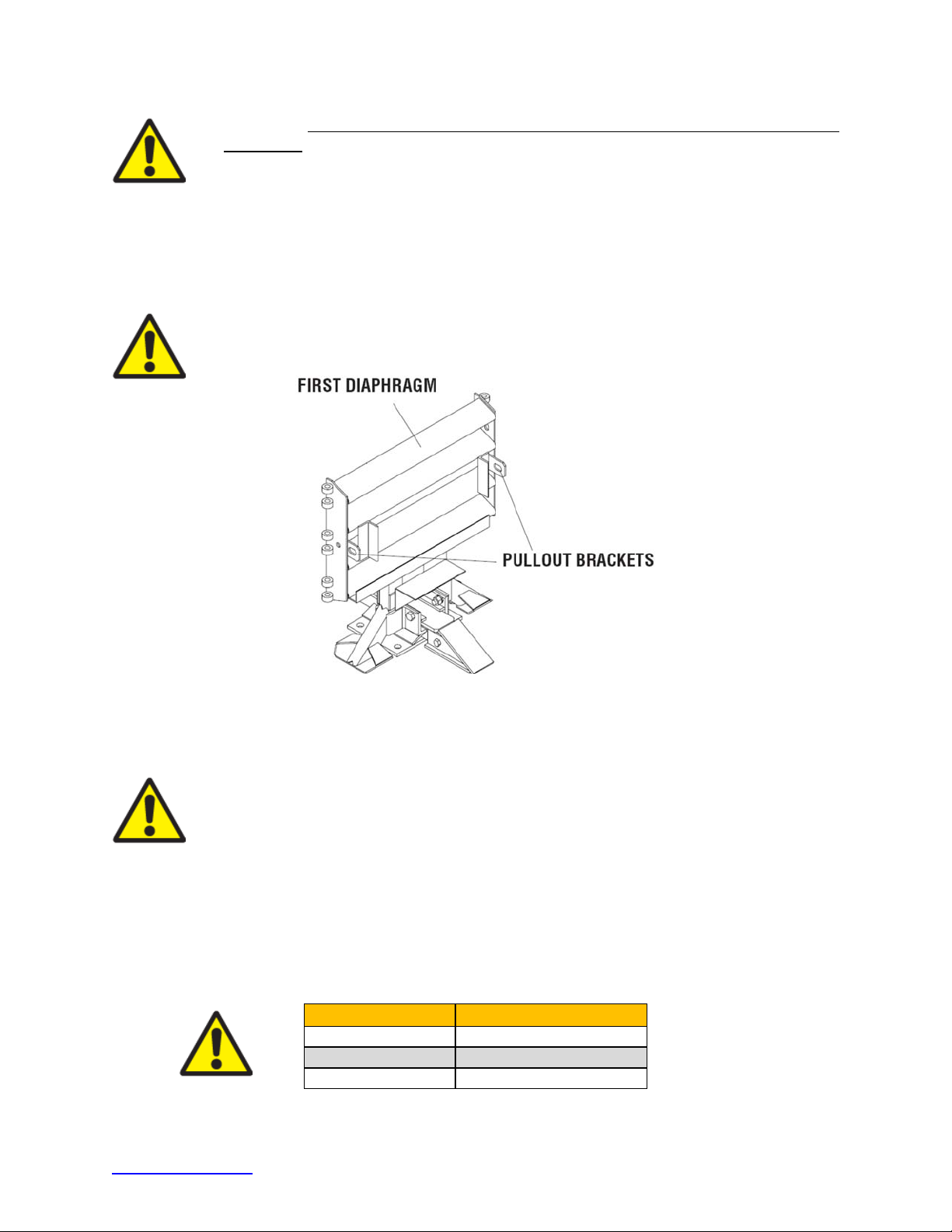
Caution:
Assembly. Do not place fingers underneath an assembled Mushroom Washer.
Parts may suddenly shift and fingers may be pinched. If the spring is still under
compression as the nut is nearing the end of the bolt, to prevent injury, make sure
that the spring is restrained with a clamp so it does not suddenly release when nut
is removed from the Mushroom Washer Bolt.
6) Attach chain to Pullout Brackets on first Diaphragm (Figure 73). Attach both ends of chain
to a heavy vehicle (such as a 1 ton pickup).
Use eye protection and gloves when refurbishing the Mushroom Spring
Warning:
Important:
original length. Have someone watch the system during repositioning to be certain
previously undetected damage does not cause the Diaphragms to bind or pull out
improperly.
Stand clear in case chain breaks or becomes disconnected.
Figure 73
Pullout
Slowly pull the QuadGuard® II forward until the system reaches its
7) Remove all crushed Cartridges from within the system.
8) Check to see that the Diaphragms are in usable condition. Diaphragms which are bowed
or have bent legs must be replaced.
9) Check that the Fender Panels are properly attached with the Mushroom Washer
Assemblies. Damaged Fender Panels and Transition Panels must be replaced
Warning:
Fender Panel Maximum gap allowed:
Narrow Systems 7/8” [22 mm]
Wide Systems 1.00” [25 mm]
trinityhighway.com 60 Revision D September 2019
Page 62
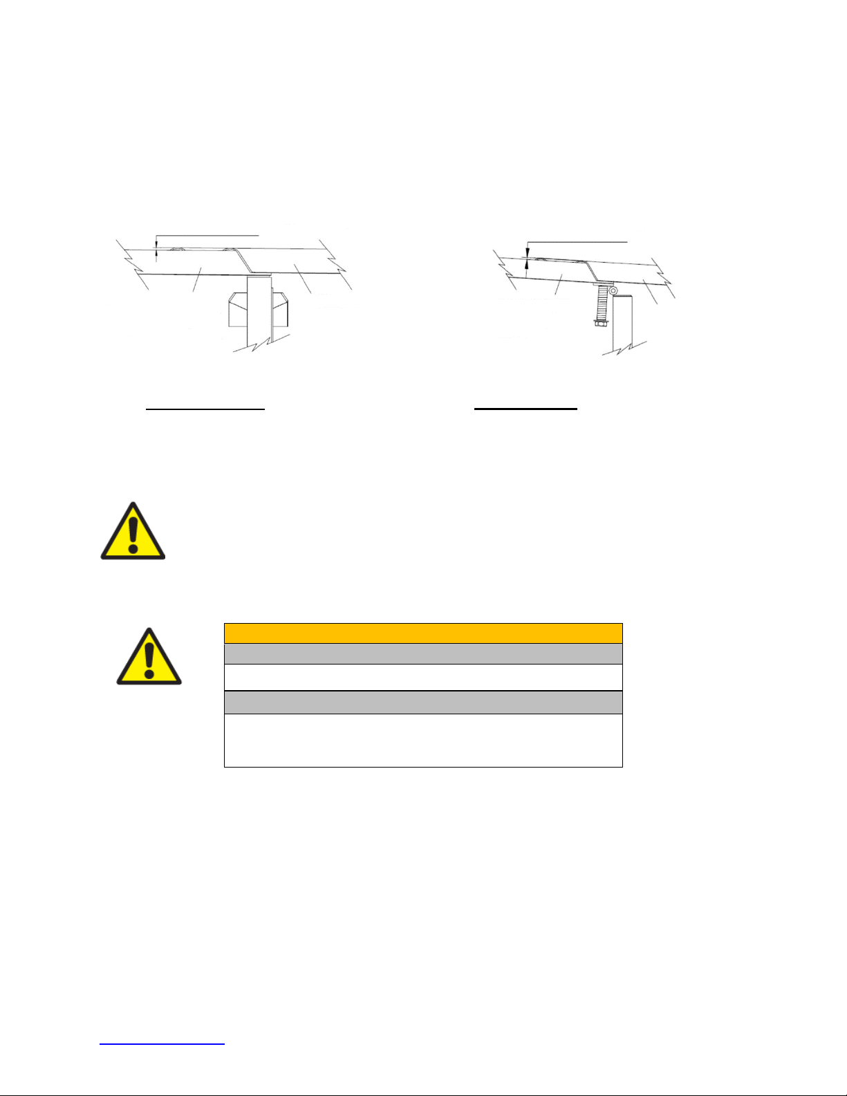
10) Check the gaps between Fender Panels. The maximum gap allowed for these
overlapping parts (including Fender Panels overlapping Panels behind the system) is
7/8” [22 mm] for narrow systems and 1.00” [25 mm] for wide systems. Be sure the
Mushroom Washer Assemblies are tightened to the end of the threads. If the gaps
between the Fender Panels are still too large, it may be necessary to replace bent parts.
MAXIMUM GAP = 7/8” [22 mm]
UNDERLYING FENDER,
TRANSITION, EXTENTION
OR SIDE PANEL
Narrow Systems Fender Panel Gap
11) Replace all crushed Cartridges. See Cartridge Placement on pages 39 and 56.
12) Remove damaged Nose Assembly and attach the new Nose (p. 36 and 37).
Important: Trinity Highway makes no recommendation whether use or
reuse of any part of the system is appropriate or acceptable following an
impact. It is the sole responsibility of the project engineer and/or the local
highway authority and its engineers to make that determination. It is critical
that you inspect this product after assembly is complete to make certain that
the instructions provided in this manual have been strictly followed.
FENDER PANEL
Figure 74
MAXIMUM GAP = 1.00” [25 mm]
UNDERLYING FENDER,
TRANSITION, EXTENTION
OR SIDE PANEL
FENDER PANEL
Figure 75
Wide Systems Fender Panel Gap
Warning:
Anchor Requirements
Anchor Studs – p. 16
Critical Clearances
Anchor Studs above nuts – Figure 54, p. 46
Fender Panel Gap Narrow – 7/8” [22 mm]
Fender Panel Gap Wide – 1.00” [25 mm]
13) Verify all bolts on the system are tight (p. 16).
14) Ensure that the site is free from any debris.
®
15) The QuadGuard
II is now ready for use.
trinityhighway.com 61 Revision D September 2019
Page 63

Parts Ordering Procedure
Make a list of all damaged parts using part descriptions shown on the components pages 7 - 11
and on the system images (p. 63 and 64). Answer the following questions in the spaces provided.
This information is necessary to receive the proper parts.
QuadGuard® II Ordering Information Chart
Description:
What is the width of the
system (p. 21)?
24” [610 mm]
30” [760 mm]
36” [915 mm]
48” [1219 mm]
69” [1755 mm]
90” [2285 mm]
126” [3200 mm]
Choices Fill in this section
What is the Number /
Type of Bays?
See Bay information on
pages 39 and 56.
What Type of Backup
Does the System Have?
Figures 9 or 10 (p. 23).
What Type of Transition
Panel?
Reference “Side Panel and
Transition Panel Types”
(pp. 24 and 42). Be sure to
specify right side, left side,
or no Transition(s).
See “How to Determine
Left/Right” on page 20.
Narrow Systems:
1 through 5
Wide Systems:
3 through 6
Concrete
Tension Strut
Quad to W
Quad to Thrie
Quad to Safety Shape
Barrier
Quad to End Shoe
4” Offset Panel
trinityhighway.com 62 Revision D September 2019
Page 64
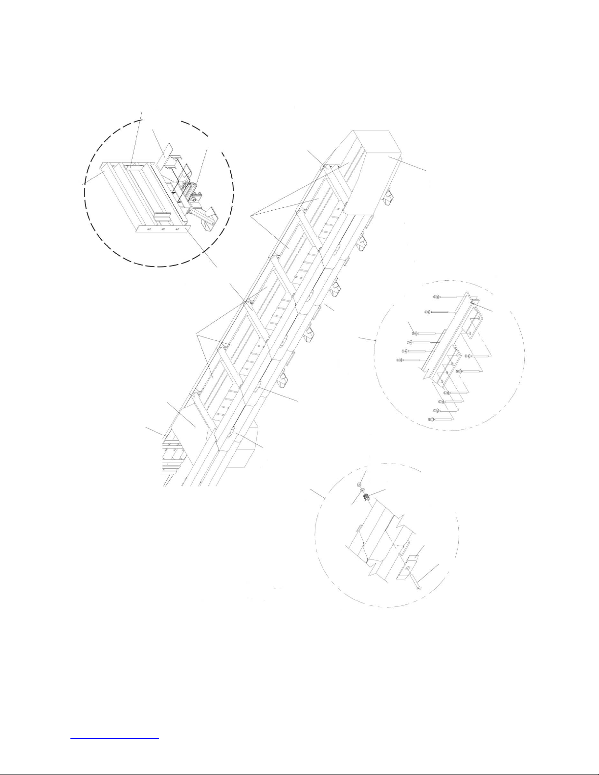
CARTRIDGE
SUPPORT
BRACKETS
MONORAIL GUIDE
DIAPHRAGM
TYPE I CARTRIDGES
DIAPHRAGM
TYPE II CARTRIDGES
BACKUP
(CONCRETE SHOWN)
FIRST DIAPHRAGM
STEEL NOSE ASSEMBLY
APPROVED ADHESIVE
WITH 3/4” X 7” STUD
MONORAIL (UNDER SYSTEM)
APPROVED ADHESIVE KIT
MONORAIL SECTION
TRANSITION PANEL
(NUMEROUS TYPES)
QUAD-BEAM FENDER PANEL
MUSHROOM WASHER ASSEMBLY
Figure 76
QuadGuard
®
II for Narrow
Roadside Obstacles
5/8” HEX NUT
5/8” X 1 3/4”
FLAT WASHER
1 1/2” SPRING
MUSHROOM WASHER
5/8” X 5” FLAT SCREW
trinityhighway.com 63 Revision D September 2019
Page 65
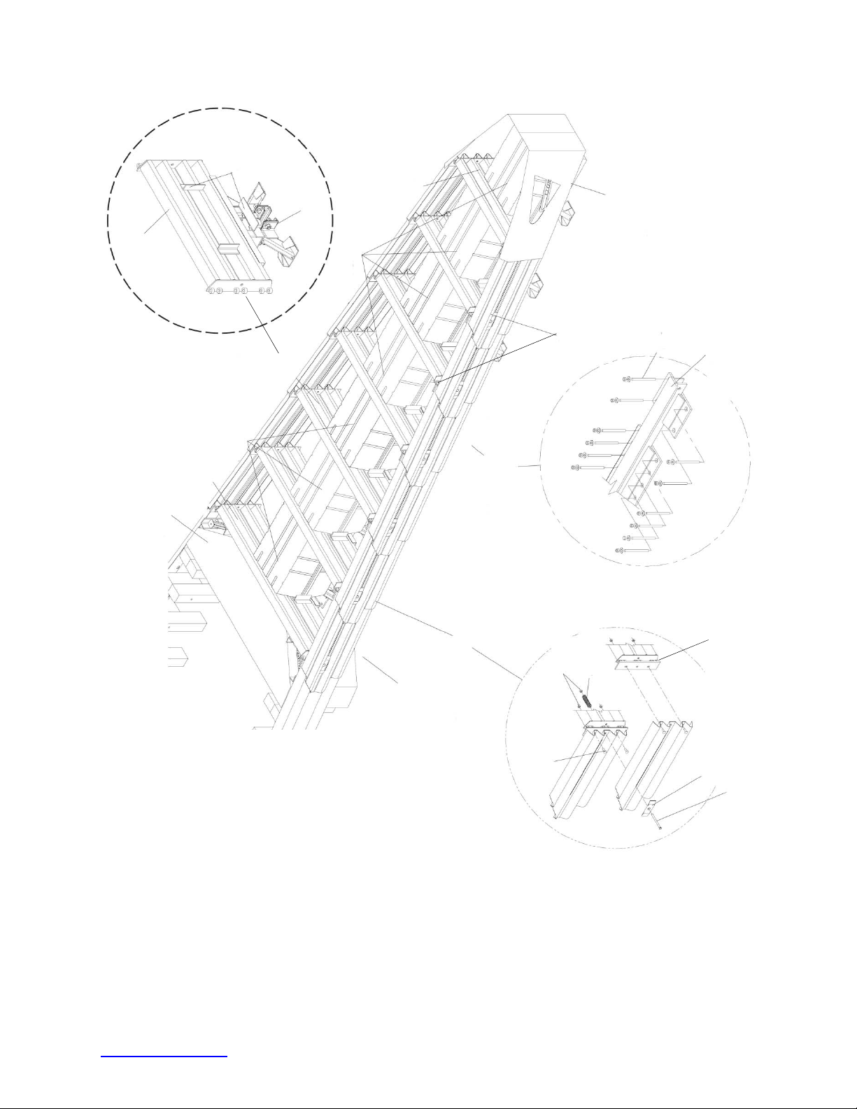
CARTRIDGE
SUPPORT
BRACKETS
FIRST DIAPHRAGM
MONORAIL GUIDE
STEEL NOSE ASSEMBLY
DIAPHRAGM
TYPE I CARTRIDGES
TRANSITION PANEL
(NUMEROUS TYPES)
BACKUP
WITH 3/4” X 7” STUD
MONORAIL SECTION
HINGE
HINGE
DIAPHRAGM
TYPE II CARTRIDGES
(CONCRETE SHOWN)
MONORAIL (UNDER SYSTEM)
APPROVED ADHESIVE KIT
5/8” RAIL NUT
6” DIE SPRING
MUSHROOM WASHER ASSEMBLY
APPROVED ADHESIVE
5/8” X 2” RAIL BOLT
QUAD-BEAM FENDER PANEL
MUSHROOM WASHER
5/8” X 8 1/2” FLAT SCREW
Figure 77
QuadGuard
®
II for Wider
Roadside Obstacles
trinityhighway.com 64 Revision D September 2019
Page 66

Notes:
trinityhighway.com 65 Revision D September 2019
Page 67

Notes:
trinityhighway.com 66 Revision D September 2019
Page 68

 Loading...