

Page 1
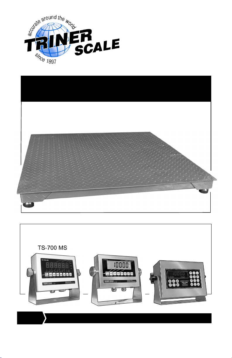
TSM Series
Low Profile Floor Scales
Set Up Guide
www.trinerscale.com SUG Version 2.0_02/15/13
Guide for setting up the Triner TSM Low Profile Floor Scale
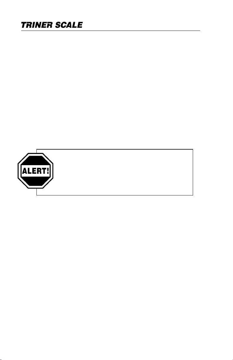
Platform and connecting to any of the following digital indicators:
TS-700 SS
7600e
DIGITAL INDICAT OR SHIPS SEPARATELY FROM WEIG HING PLATFORM
NOTICE:
Page 2

©Triner Scale & Mfg. Co, Inc. 2013. All rights reserved.
The information contained herein is the property of Triner
Scale and is supplied without liability for errors or
omissions. No part may be reproduced or used except as
authorized by contract or other written permission. The
copyright and the foregoing restriction on reproduction and
use extend to all media in which the information may be
embodied.
Specifications are subject to change without notice.
For Parts, Service, and Support
Look for a Service Sticker on ALL sides of the Digital
Indicator. If a service sticker is present, contact the
servicing dealer. The servicing dealer is usually local to
your area and can quickly respond for onsite service.
Your local servicing dealer can also perform periodic
calibration services according to your requirements.
If you are unable to obtain service locally, contact our
factory service department directly. We would be happy to
assist you.
Phone: 1-800-238-0152
Fax: 1-662-890-2386
Email: info@trinerscale.com
Mail: Triner Scale & Mfg. Co., Inc.
8411 Hacks Cross Rd.
Olive Branch, MS 38611
Page 3

Set Up Guide | Floor Scale
1
Table of Contents
Introduction ........................................... 2
TSM Series Weighing Platform ......... 2
Digital Indicator ................................. 3
Weighing Platform Set Up ..................... 4
Site Preparation ............................... 4
Installing and Leveling the Platform... 4
Connecting the Digital Indicator to the
Weighing Platform ................................. 6
Standard TSM Series Indicators ....... 6
Connecting a TS-700 MS Indicator ... 6
Connecting a TS-700 SS Indicator.... 7
Connecting a 7600e Indicator ........... 7
JBox Wiring Diagram ........................ 9
Appendix A.......................................... 10
Troubleshooting Guide.................... 10
Periodic Maintenance ..................... 13
Appendix B.......................................... 15
Parts List ......................................... 15
Warranty ............................................. 16
Page 4

Set Up Guide | Floor Scale
2
Introduction
THE TSM SERIES WEIGHING PLATFORM
The TSM Series Floor Scale weighing platform is a
fully electronic, low profile platform, engineered to
provide years of reliable service. It is available in
wide range of sizes from 24” x 24” to 96” x 120”, and
capacities from 1,000 lbs to 20,000 lbs.
All platforms are equipped with four, corner mounted
NTEP approved loadcells that are recessed into the
scale frame for protection. Also included is a signaltrim summing board enclosed in a watertight
junction box. The junction box is accessible from the
top of the scale for ease of service.
The platform utilizes precision “ball and cup” style
adjustable leveling feet designed to compensate for
irregularities in the floor.
OPTIONS
• Foot Retaining Plates
• Access Ramps
• Side Protection Guards
• Indicator Mounting Stand
• Pit Frame for In-ground Installations
UNPACKING THE PLATFORM
All Triner Low Profile Floor Scale weighing
platforms are shipped LTL on a pallet. Remove
the packing material and inspect the scale for
any damage that may have been caused during
shipment.
THE DIGITAL INDICATOR, LEVELING FEET AND
ANY SMALL ACCESSORIES ORDERED ARE
SHIPPED SEPARATELY VIA UPS GROUND.
Page 5
Set Up Guide | Floor Scale
3
DIGITAL INDICATOR
TSM weighing platforms are typically shipped as a
complete weighing system which includes a factory
calibrated digital indicator.
For operation of the scale/digital indicator, please
see the User’s Guide that is included with the digital
indicator.
BE SURE TO UNPACK ALL ITEMS IN THE
DIGITAL INDICATOR SHIPPING CARTON.
The scale comes factory calibrated with
the digital indicator. There is no need to
calibrate the scale. Do not attempt to
calibrate the scale without contacting a
qualified scale technician or the factory.
Page 6

Set Up Guide | Floor Scale
4
Weighing Platform Set Up
SITE PREPARATION
The scale should not be loaded beyond its capacity.
Do not select a site where overweight loads would
have to cross the platform. Avoid areas where the
scale might receive damaging side impacts from
wheels or forklift tines.
The interface cable that connects the scale platform
to the digital indicator MUST be protected from
crushing, cutting, or moisture damage. Protecting
the cable with conduit is recommended.
THE MOST COMMON REASON FOR THE
SCALE TO BECOME INOPERABLE IS DUE TO
INTERFACE CABLE DAMAGE. BE SURE TO PROTECT
THE CABLE AND KEEP IT OUT OF HARM’S WAY.
For best results, the scale should be installed on
smooth level concrete. Installing the scale on dirt,
gravel or asphalt is not acceptable.
INSTALLING AND LEVELING THE PLAFTORM
1. Locate the four leveling feet (typically packed
with the digital indicator). On the underside of
the weighing platform, thread the leveling feet
all the way into each of the four loadcells
located at the corners of the platform.
2. Place the scale on the floor in the location of
intended use. Remove all shipping guards.
3. Adjust any “high” corners not in contact with
the floor by inserting a flat blade screwdriver
into the top access hole over the leveling
foot, and with a clockwise motion, screw the
Page 7

Set Up Guide | Floor Scale
5
foot downward until solid contact is made
with the floor.
4. When all feet are in contact with the floor,
check the platform with a level to make sure
it is within ¼ inch of level.
5. MAKE CERTAIN that the platform does not
rock from corner to corner. Any amount of
rocking will result in inaccurate weighing.
6. If desired, tighten the jam-nut against the
bottom of the load cell to lock the foot into
place.
Page 8

Set Up Guide | Floor Scale
6
Connecting The Digital Indicator To
The Weighing Platform
STANDARD TSM SERIES DIGITAL INDICATORS
The TSM Series Low Profile Scale is typically
purchased as a complete, factory calibrated
weighing system, which includes a compatible digital
indicator and all required cables and cords. The
digital indicator model will vary according to which
floor scale system was purchased. This section
covers connecting the TSM floor scale platform to
digital indicator models TS-700 MS, TS-700 SS and
7600e.
THE CONNECTING CABLE WILL BE FOUND IN
ONE OF TWO LOCATIONS, DEPENDING ON THE
MODEL OF INDICATOR PURCHASED. IT WILL BE IN
THE SHIPPING CARTON WITH THE INDICATOR, OR
BUNDLED INSIDE THE JUNCTION BOX AREA INSIDE
THE WEIGHING PLATFORM.
For all Models: Locate the junction box access
plate on the outside edge of the weighing platform
deck. Unscrew the two screws and remove the
plate.
Connect the indicator to the platform according to
the model, as follows:
CONNECTING A TS-700 MS INDICATOR
(The interface cable is pre-wired to the weighing
platform junction box and it quick-connects to
the digital indicator)
1. Feed the cable out of the junction box area
through the hole at the bottom of the cavity.
2. Connect the cable to the digital indicator.
Page 9

Set Up Guide | Floor Scale
7
a. Gently insert the cable connector into
the socket on the underside of the digital
indicator and fully press in.
b. Screw on the connecting collar and
lightly tighten down.
3. Replace the junction box access plate.
4. Connect the AC adapter to the indicator and
then to the wall outlet.
5. Turn the Indicator on. After the power up
sequence the display should indicate Zero. If
it does not, press the ZERO key.
6. When the scale reads Zero it is ready for
use.
CONNECTING A TS-700 SS INDICATOR
-- OR -CONNECTING A 7600E INDICATOR
(The interface cable is pre-wired to the digital
indicator and requires connecting the five wire
leads into the weighing platform junction box)
1. Feed the five wire leads of the cable up
through the hole in the bottom plate of the
junction box area inside the weighing
platform. Gently pull a generous amount of
slack cable up through the hole.
2. Remove the junction box faceplate.
3. REFERING TO THE FOLLOWING FIG. 3.0
JBOX WIRING DIAGRAM:
a. Using a small Flat head screwdriver,
loosen the terminal screws.
b. Feed the five wire leads into the junction
box through the watertight collar.
Page 10

Set Up Guide | Floor Scale
8
c. Carefully insert the bare end of the wire
into the terminal opening.
d. While holding the wire in position,
tighten down the terminal screw. After
tightening, gently pull the wire to make
sure it’s secure.
e. Repeat the process for the remaining
wires.
WHEN INSERTING THE WIRE INTO THE
TERMINAL CLAMP, MAKE SURE THE CLAMP SECURES
THE BARE WIRE AND NOT THE COLORED INSULATION
OF THE WIRE.
IF THE BARE END OF THE WIRE IS NOT
PROPERLY SECURED, THE SCALE WILL NOT
OPERATE CORRECTLY! THIS WILL BE THE MOST
LIKELY CAUSE OF ANY PROBLEM YOU MAY HAVE
WHEN USING THE SCALE FOR THE FIRST TIME.
4. Once all the wires are secure, pull out any
excess slack in the cable through the liquid
tight fitting.
5. Tighten the liquid tight fitting nut to secure
the cable to prevent moisture from entering
the junction box.
6. Replace the junction box faceplate.
7. Replace the junction box access plate.
8. Connect the AC adapter to the indicator and
then to the wall outlet. If the unit has and AC
power cord, connect it to the wall outlet.
Page 11

Set Up Guide | Floor Scale
9
9. Turn the Indicator on. After the power up
sequence the display should indicate Zero. If
it does not, press the ZERO key.
10. When the digital indicator displays “0” the
scale is ready for use.
Fig. 3.0 JBox Wiring Diagram
(For clarity, loadcell wiring is omitted)
Page 12

Set Up Guide | Floor Scale
10
APPENDIX A: TROUBLESHOOTING AND
PERIODIC MAINTAINANCE
A.1 Troubleshooting Guide
Condition
Possible Problem & Correction
The system does not
operate – No Display.
• Power disconnected or bad power
supply: Check outlet first. Test the
AC adapter or power supply.
• Indicator fuse blown: Replace
fuse, check for cause.
• Interface Cable cut or
disconnected: Replace or Properly
repair cable.
• Interface Cable wiring problem:
Check connections inside junction
box and at indicator.
Display stays at Zero.
Scale will not weigh
anything.
• Item may be too light for scale
resolution.
• Interface Cable cut or
disconnected: Replace or Properly
repair cable.
• Interface Cable wiring problem:
Check connections inside junction
box and at indicator.
• Load cell connections faulty:
Check load cell connections inside
junction box.
• Debris under the scale platform:
Check and clean debris from
under the platform (Periodic
Maintenance).
• Indicator faulty. Service or replace
indicator.
Page 13

Set Up Guide | Floor Scale
11
Condition
Possible Problem & Correction
Scale displays erratic
weights.
• Interface Cable cut or
disconnected: Replace or
Properly repair cable.
• Interface Cable wiring problem:
Check connections inside
junction box and at indicator.
• Platform not level: Level the
scale by properly adjusting the
leveling feet.
• Load cell connections faulty:
Check load cell connections
inside junction box.
• Load cell or load cell cable
damage: Inspect load cell
cables. Test and replace
Loadcell if needed.
• Bad power supply: Check outlet
first. Test the AC adapter or
power supply.
• Debris under the scale platform:
Check and clean debris from
under the platform (Periodic
Maintenance).
• Indicator faulty. Use simulator
to test for stability. Service or
replace.
Page 14

Set Up Guide | Floor Scale
12
Condition
Possible Problem & Correction
Scale consistently
displays weights that are
too high or too low.
• Indicator not properly adjusted
to zero: Zero the indicator
according to the indicator
manual.
• Platform binding: Provide
adequate clearance for free
platform movement. Make sure
a ramp(s) is not touching the
scale. Remove any debris
under and around the scale
platform.
• Indicator not calibrated
properly: Calibrate the system
according to the indicator
manual.
• Load cell(s) faulty: Test and
replace load cells if necessary.
Page 15

Set Up Guide | Floor Scale
13
A.2 Periodic Maintenance
The TSM Series Low Profile Scale is designed and
engineered to require very little maintenance. Follow
the basic guidelines below:
1. Periodically clean any debris from under and
around the scale. If debris such as broken wood from
pallets wedges between the scale platform and the
ground or a ramp, erratic weights will result.
2. Provide adequate clearance for free platform
movement. Make sure a ramp(s) is not touching the
scale. Remove any debris under and around the scale
platform.
3. Make sure the scale is level. Adjust the leveling
feet if required to make sure all four feet are in contact
with the floor.
4. Periodic Calibration Notes
a. The scale is shipped factory calibrated.
b. It is recommended you have your scale
calibrated once a year with Test Weights to
assure accuracy.
c. You should refer to your quality system
guidelines to determine your particular
calibration frequency.
d. If calibration is required, refer to the
indicator manual to determine the correct
calibration procedures.
e. For optimum calibration, load the scale with
Test Weights equal to 70%-80% of the
scales capacity.
f. The scale may be calibrated with less Test
Weight. Try to use at least 40% of the
scales capacity if possible.
Page 16

Set Up Guide | Floor Scale
14
g. Calibrating the scale with anything other
than industry standard test weights is not
recommended or reliable. Refer to your own
quality standards to determine what kind of
test weight is acceptable.
-- End --
Page 17

Set Up Guide | Floor Scale
15
APPENDIX B: PARTS LIST
Part Description
Part Number
Four load cell steel NEMA 4x junction
box assembly with signal trim summing
card
JBOX
1/2 –20 precision ball and cup leveling
foot
FOOT07
2.5k (2,500 lb) Sheerbeam load cell
LC002
5k (5,000 lb) Sheerbeam load cell
LC004
Load cell Bolt M12 x 1.75 x 50mm
LCB01
Load cell Bolt ½-20 x 1 ¾
LCB02
Eye Bolt M12
M12EB
Leveling foot retaining plate, 3”
RTP
Top access plate screw M8 x 1.25
TPS01
Page 18

Set Up Guide | Floor Scale
16
LIMITED WARRANTY
What is Covered: Triner Scale & Mfg. Co. Inc. warrants to the first end user customer of the Triner Scale
product enclosed w ith this limited warranty statement that the product, if purchased and used in the
United States, conforms to the manufacturer’s specifications and will be free from defects in workmanship
and materials for a period of one (1) year from the date of original purchase.
What Triner Scale Will Do to Correct Problems: Sho uld your Triner Scale product prove defective
during the warranty period, please call Triner Scale at (800) 238-0152 for warranty repair instructions and
return authorization. Triner Scale will, at its option, repair or replace on an exchange basis th e defective
unit as follows:
PARTS
New or comparable rebuilt parts in exchange for defective parts for one (1) year after original purchase.
LABOR
Carry-In or mail in service for ninety (90) days from the date of original purchase. Labor and shipping cost
after the ninety (90) day period will be charged to you.
If you are authorized by Triner Scale to ship the product to Triner Scale for repair, it is your responsibility
to securely package the product in its original container or an equivalent and provide proof of the date of
original purchase. You will be respo nsible for shipping costs to Triner Scale repair facility. When warranty
service involves the exchange of the product or a part, the exchanged product may be new or previously
repaired to the Triner Scale standard of quality. Exchange or replacement products or parts assume the
remaining warranty period of the product covered by this limited warranty.
What this Warranty Does Not Cover: This warranty covers only consumer use in the Un ited States.
Triner Scale is not responsible for warranty service should the Triner Scale label or logo or the serial
number be removed or the product fail to be properly maintained or fa il to function properly as a result of
misuse, abuse, improper installation, neglect, improper shipping, damage caused by disasters such as
fire, flood, and lightning, improper electrical current, interaction with non-Triner Scale products, or service
other than a Triner Scale Authorized Service. Packaging and shipping costs incurred in presenting your
Triner Scale product for warranty service are your responsibility. If a claimed defect cannot be identified or
reproduced in service, you will be held responsible for costs incurred.
THE WARRANTY AND REMEDY PROVIDED ABOVE ARE EXCLUSIVE AND IN LIEU OF ALL OTHER
EXPRESS O R IMPLIED WARRANTIES INCLUDING, BUT NO T LIMIT ED TO, THE IMP LIED
WARRANTIES OF MERCHANTABILITY OR FITNESS FOR A PARTICULAR PURPOS E. SOME LAWS
DO NOT ALLOW THE EXCLUSION OF IMPLIED WARRANTIES. IF THESE LAWS APPLY, THEN ALL
EXPRESS AND IMPLIED WARR ANTIES ARE LIMITED TO THE WARR ANTY PERIOD ID ENTIFIED
ABOVE. UNLESS STATED HER EIN, ANY STATEM ENTS OR REPRESENTATIONS MADE BY ANY
OTHER PERSON OR FIRM ARE VOID. EXPECT AS PROVIDED IN THIS WRITTEN WARRANTY,
NEITHER TRINER SCALE & MFG. CO. INC. NOR ITS AFFILIATES SHALL BE LIABLE FOR ANY LOSS,
INCONVENIENCE, OR DAMAGE, INCLUDING DIRECT, SPECIAL, INCIDENTAL OR
CONSEQUENTIAL DAMAGES, RESULTING FROM THE USE OR INABILITY TO USE THE TRINER
SCALE PRODUCT, WHETHER RESULTING FROM BREACH OF WARRANTY OR ANY OTHER LEGAL
THEORY.
No terms, condition, understanding, or agreements, purporting to modify the terms of this warranty shall
have any legal effect unless made in writing and signed by a corporate officer of the seller. This warranty
gives you specific legal rights, and you my have other rights, which vary from jurisdiction to jurisdiction.
TRINER SCALE & MANUFACTURING COMPANY INC.
8411 Hacks Cross Road
Olive Branch, MS 38654-4010
Tel (662) 890-2385 • Fax (662) 890-2386
 Loading...