

Page 1

User’s Guide
TS 700-SS Digital Indicator
Series 3
Version 3.0 11/15/10
Triner Scale & Mfg. Co., Inc
(800) 238-0152
Page 2
!!!! CALIBRATION WARNING !!!!
Calibration AND Inspection of calibration properties is prohibited
unless done so by a qualified scale technician.
WARNING
The indicator is the static and sensitive equipment,
cut off the power during electrical connections,
internal components touched by hand is prohibited,
and please take the measure of anti-static.
© 2010 Triner Scale. All rights reserved.
Page 3

1
Table of Contents
Specifications __________________________________ 2
Load Cell Connections ___________________________ 3
Serial Port Connections __________________________ 4
Operation ______________________________________ 5
Parameters and Settings _________________________ 7
Data Output Formats ___________________________ 15
Error Codes ___________________________________ 19
Factory Default Settings _________________________ 20
Page 4

2
Specifications
Technical parameters
Accuracy class 6000 e
Resolution Display: 30, 000 ADC: 2,000,000
Zero stability error TK
0
< 0.1µV//K
Span stability error TK
spn
< ± 6 ppm//K
Sensitivity (internal) 0. 3 µV /d
Input voltage -30~30mV DC
Excitation circuit 5 VDC, 4 wire connection,
Load Cell Max 8 load cell of 350Ω
AC power AC100~250V
Operation temperature - 10 °C ~ + 40 °C
Operation humidity ≤90%RH
Storage temperature - 40 °C ~ + 70 °C
Battery Operation
- Before operating with the internal battery, charge the battery fully, for
18+ hours.
- The battery icon in the lower right area of the display indicates battery
status:
3 bars = fully charged
2 bars = half discharged
1 bar = 2/3rds discharged
No bars = discharged/must be recharged. .
- In order to keep the battery in its best condition, it is recommended the
battery be fully discharged and recharged once a month.
Page 5
3
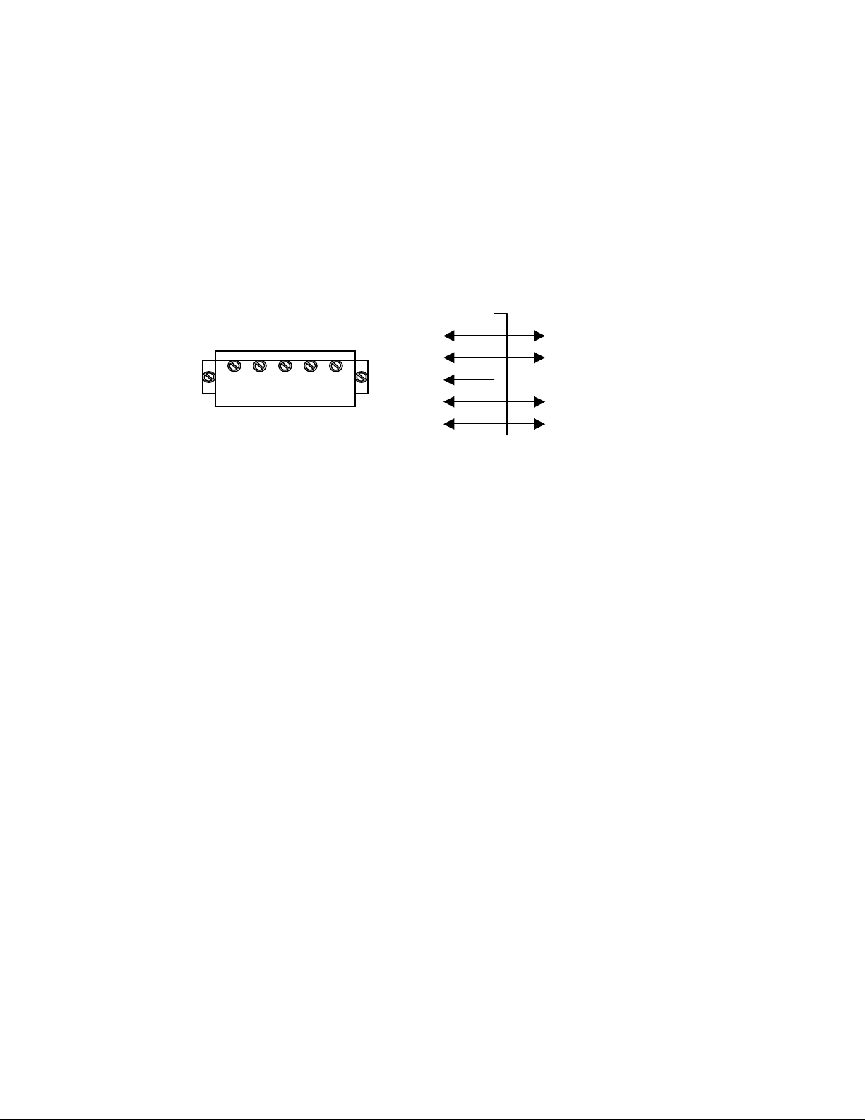
Load Cell Connections
The indicator can connect with a maximum of eight of 350Ω load cells, 4
wire or 6 wire configurations.
Excitation voltage for the load cell is 5VDC, the largest output current
120mA.
Terminal Block on Circuit Board:
Circuit Board Terminals Load cell
+EXC + voltage
+SIG + output signal
HD --------- Shielded wire
- SIG - output signal
-EXC -SIG HD +SIG +EXC - EXC - voltage
Page 6
4
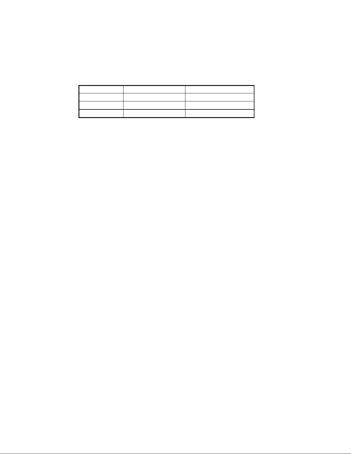
Serial Port Connection
RS232 Terminal on Circuit Board
DB9
Definition
Function
2
TXD
Sending data
3
RXD
Receiving data
5
GND
Ground interface
Note: if RS485, The connection pin is 2 and 5 pin.
Page 7
5
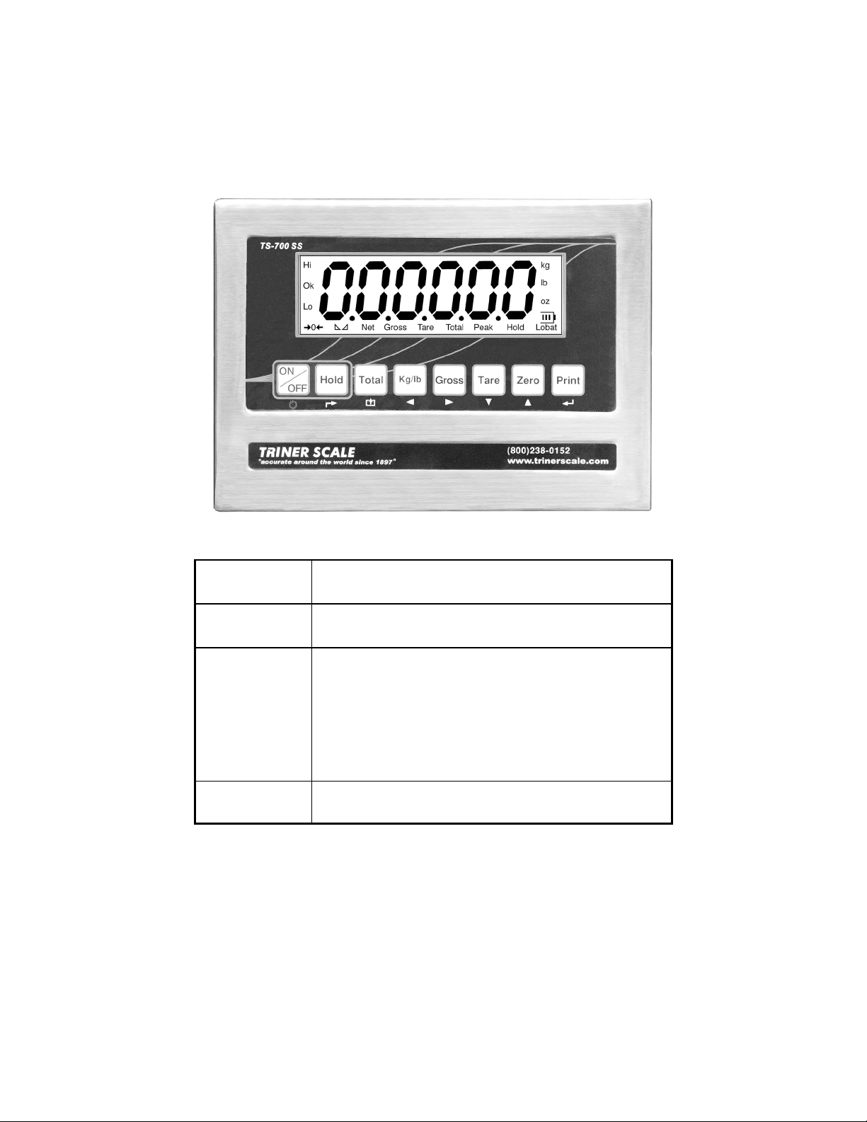
Operation
Keys and Their Functions
KEY
OPERATION / FUNCTION
On/Off
Press and hold for 2+ seconds to operate.
Hold
To Hold Weight on Scale
- With weight on scale, press key to hold weight.
To Hold Peak Weight of Multiple Weighings
- Without weight on scale, press key to put indicator
in peak hold mode.
To Remove Hold Function
- Press key again to return to normal operation.
Total
- With weight on scale, press key to place weight
and count in memory. Remove weight, place next
Page 8

6
item on scale, press Total to add weight to total
weight and total count.
- To view totals, press Total and Print key at the
same time. The total weight will flash continuously.
- To go out of view totals mode, press and hold the
Total key. “Clr n” will display.
- If you wish to continue adding to the totals, press
the Print to accept the “Clear-No” prompt. Continue
weighing and adding items as required.
- If you wish to clear the totals memory, press the
Zerro/Up Arrow key to change the “Clr n” display
to “Clr y”. Press the Print key to accept the
kg/lb
Change pounds/kilograms
Gross
For use after a TARE weight has been stored in the
indicator. Press key to toggle view between gross
and net weight.
PLEASE NOTE that there may be a momentary
pause in the display when going from gross to tare
weight.
Tare
- With weight on the scale, press to Tare the weight.
- Press again to remove Tare weight.
Zero
Press key to zero the scale.
Print
Press key to print a ticket (requires optional printer).
Page 9

7
Parameters and Settings
CAUTION: Use care when accessing and adjusting your indicator’s
parameters. Several parameters can be accessed that, if altered, will
change your indicator’s operations.
To access and adjust the TS-700 SS parameters:
Press the PRINT and HOLD keys. “C” will display. Release the keys.
“C08” will display, with the 8 flashing. The digit flashing is the active
digit, and can be adjusted up or down by using the ZERO/UP
ARROW or TARE/DOWN ARROW key. Use the KG-LB/LEFT
ARROW key and the TARE/RIGHT ARROW KEY to change which
units digit is active (flashing).
TIP: You can move forward through all parameters and view
the settings by pressing the PRINT/ENTER key repeatedly.
Navigate to the setting parameter you wish to adjust and use the
arrow keys to change the settings values. Press the PRINT/ENTER
key to accept your settings, then press the TOTAL/EXIT key.
EXAMPLE: To adjust the date setting in parameter C16:
- With “C08” flashing, use the down arrow key to reduce the
flashing 8 to 6. Use the left arrow key to make 0 the active digit.
- Use the up arrow key to increase the 0 to 1.
- “C16” will display. Press the PRINT/ENTER key.
- The display will show digits for month, day and year. Use the
arrow keys as discussed above to navigate to and change the
digits.
- Press the PRINT/ENTER key to accept your settings.
- Press the TOTAL/EXIT key to exit.
Page 10

8
Function
Setting Parameter
Parameters Settings
Warning tone
C08
Options:
0 = no warning tone
1 = warning tone on
Automatic
power off
C09
Options:
0 = no auto power off
10 = power off automatically if no
change within 10 minutes.
30 = power off automatically if no
change within 30 minutes.
60 = power off automatically if no
change within 60 minutes.
Power saving
setting
C10
Options:
0 = close power saving setting
3 = close display if no change
within 3min.
5 = close display if no change
within 5 min.
Hold function
C11
Options:
0 = no hold function
1 = Peak hold
2 = Data Hold
- Peak-hold shows the max. load
of multiple weighings.
- Data hold locks the current
weight value.
Kg/lb
conversion
C12
C12 = 0 disable kg/lb conversion
C12 = 1 kg/lb conversion is ok
Upper/lower
limit alarm
C13
Upper limit alarm
value
Enter numeric values for upper
and lower checkweighing limits.
Page 11

9
C14
Lower limit alarm
value
Inner Code
display
C15
Enter C15 to check the inner
code.
C16
Date
Enter C16, set the date, from left
to right: year/month/day
Date and time
C17
Time
Enter C17, set the time from left
to right: hour/min./sec.
C18
Serial interface data
output method
Options:
0 = Close serial interface data
output
1 = Continuous sending, connect
big display
2 = Print method, connect printer.
3 = Command request method ,
connect computer.
4 = PC continues sending format,
connect computer.
5 = PC/ big display continuous
sending format.
Communication
setting
C19
Baud rate
Options:
0=1200/1=2400/2=4800/3=9600
C20
Manually zero range
Options:
0 = disable manual zero setting
1 = ±1% max capacity
2 = ±2% max capacity
4 = ±4% max capacity
10 = ±10% max capacity
20 = ±20% max capacity
100 = ±100% max capacity
Zero range
CAUTION;
Changing these
parameters will
effect the indicator’s
performance.
C21
Initial zero range
Options:
0 = no initial zero setting
Page 12

10
1 = ±1% max capacity
2 = ±1% max capacity
5 = ±1% max capacity
10 = ±1% max capacity
20 = ±1% max capacity
C22
Automatically zero
tracking range
Options:
0 = disable zero tracking
0.5 = ±0.5d
1.0 = ±1.0d
2.0 = ±2.0d
3.0 = ±3.0d
4.0 = ±4.0d
5.0 = ±5.0d
Note:
1. d = division
2. the zero tracking range can not
more than manual zero range.
Zero tracking
CAUTION;
Changing these
parameters will
effect the
indicator’s
performance.
C23
Automatically zero
tracking time
Options:
0 = disable zero tracking time
1 = 1 second
2 = 2 seconds
3 = 3 seconds
Overload
range
C24
CAUTION;
Changing these
parameters will effect the
indicator’s performance.
option:00= close overload range
01d~99d
remark:d =division
Negative
display
C25
Options
:0 = -9d
10 = 10% max. capacity
20 = 20% max. capacity
50 = 50% max. capacity
100 = 100% max. capacity
Page 13

11
C26
Standstill time
Options:
0 = quick
1 = medium
2 = slow
Standstill time
CAUTION;
Changing these
parameters will
effect the indicator’s
performance.
C27
Standstill range
Options:
1 = 1d 2 = 2d
5 = 5d 10 = 0d
(d = division)
Digital filter
CAUTION;
Changing these
parameters will
effect the indicator’s
performance.
C28
To compensate for
unstable loads on
the weighing
platform (for
example, animal
weighing).
Options:
0 = close dynamic filter
1 = 1 digital filter strength
2 = 2 digital filter strength
3 = 3 digital filter strength
4 = 4 digital filter strength
5 = 5 digital filter strength
6 = 6 digital filter strength
CAUTION;
Changing these
parameters will
effect the indicator’s
performance.
C29
Noise filter
0 = disable noise filter
1 = 1 digital filter strength
2 = 2 digital filter strength
3 = 3 digital filter strength
C30
Print time and date
C30 = 0 yy.mm.dd
C30 = 1 mm.dd.yy
C30 = 2 dd.mm.yy
C30 = 3 yy.mm.dd
Analog output
setting
C31 output type
C31 = 0 0~5Vouput
C31 = 1 4~20mA output
4~20mA
current
calibrate
C32
(RESERVED)
Page 14

12
Relay output
setting
C33 Relay output
C33 = 0 close relay output
C33 = 1 Open relay output
function 1
C3 = 2 Open relay output
function2
C33 = 3 Preserved menu
Mutli
communication
add.
C34 Communication
add.
C34 = 0~99 Add. Code
(RESERVED)
Wireless
communication
C35
C35 = 0~99 signal (RESERVED)
Gravity of
calibration
location
C36
CAUTION;
Changing these
parameters will effect the
indicator’s performance.
C36 = 9.7000~9.9999
Gravity of
destination
C37
CAUTION;
Changing these
parameters will effect the
indicator’s performance.
C37 = 9.7000~9.9999
Version No.
C38
Preserved
menu
C39
Page 15

13
Data Output Formats
Remote Display Format
Output continuous format
S
T
X
S
W
A
S
W
B
S
W C X X X X X X X X X X X
X
C
R
C
K
S
1
2 3 4
5
6
State A
Bits0,1,2
0 1 2
Decimal point position
1 0 0
XXXXXX0
0 1 0
XXXXXXX
1 1 0
XXXXX.X
0 0 1
XXXX.XX
1 0 1
XXX.XXX
Bits3,4
Division
0 1 X1
1 0 X2
State B
BitsS
function
Bits0
gross=0, net=1
Bits1
Symbol: positive =0,negative =1
Bits2
Overload(or under zero)=1
Bits3
dynamic=1
Bits4
unit:lb=0, kg=1
Bits5
Constant 1
Bits6
Constant 0
State C
Page 16

14
Bit2
Bit1
Bit0
unit
0 0 0
Kg or lb
0 0 1
g
0 1 0
t
Bit 3
printing=1
Bit 4
Extend
display=1
Bit 5
Constant 1
Bit 6
Constant 0
PC Computer Continuous Sending Format
, ,
CR
LF
S 1 S 2 S 3 Data S 4
S1: weight status, ST= standstill, US= not standstill, OL= overload
S2: weight mode, GS=gross mode, NT=net mode
S3: weight of positive and negative, “+” or ” –“
S4: “kg” or “lb”
Data: weight value, including decimal point
CR: carriage return
LF: line feed
Serial Interface Reception Command
RS232COM serial interface can receive simple ASCII command.
Command word and role as follows:
Command
NAME
Function
T
TARE
Save and clear tare
Z
ZERO
Zero gross weight
P
PRINT
Print the weight
R
G.W/N.W
Read gross weight or net weight
C
Kg/lb
Kg/lb conversion
G
G.W
Check gross weight at net weight mode
Page 17

15
R command receive data format
5.4 Print format
ID.NO. 004 (Serial No.)
Date: XX.XX. XX (yy.mm.dd)
Time: XX.XX.XX (hh.mm.ss)
GROSS 8.88kg (gross weight)
TARE 2.88kg (tare)
NET 6.00kg (net weight)
5.5 PC or Big display continuous sending format
Page 18

Page 19

17
Error Codes
ERROR
REASON
SOLUTION
UUUUUU
1. Overload
2. wrong connection
with load cell
3. load cell has quality
problem.
1. reduce the weight
2. check load cell connection
3. inspection load cell. Check
the input and output
nnnnnnn
1. calibration is no
good
2. wrong connection
3. load cell has quality
problem
1. check scale is resisted or
not, foot is kept level or not.
2. check load cell connection.
3. checking load cell: check
input and output resistance to
judge it is good or not.
ERR1
During calibration, not
input the weights or
the weight is overload
Input the correct weights
ERR2
During calibration , the
weights is below than
Min. required weights
The calibration weights
Minimum is 10% of Max. cap.
Recommend 60%-80% of Max.
Cap.
ERR3
During calibration, the
input signal is
negative
1. check the connection is
correct
2. check load cell is no
problem
3. recalibration if still wrong
change the PCB
ERR4
During calibration, the
signal is unstable
After the platform is stable,
start calibration
ERR5
Change PCB
Page 20

18
Factory Default Settings
Parameter
instruction
Default
C01
Calibration
1
C02
Decimal digits
0
C03
Resolution
1
C04
Max. capacity
10000
C05
Empty calibration
0
C06
Capacity calibration
0
C07
Restore default
0
C08
Warning tone
1
C09
Power-off automatically
0
C10
Power saving mode
0
C11
Hold function
0
C12
Prohibit kg/lb conversion
1
C13
Upper limit alarm
000000
C14
Under limit alarm
000000
C15
Inner code
C16
Date setting
C17
Time setting
C18
Serial interface data output
0
C19
Serial interface Baud rate
3(9600)
C20
Zero manually
10
Page 21

19
C21
Initial zero
10
C22
Zero tracking range
0.5
C23
Zero tracking time
1
C24
Overload range
9
C25
Negative range
10
C26
Standstill time
1
C27
Standstill range
2
C28
Dynamic filter
0
C29
Noisy filter
2
C30
Print format
0
C31
Analog signal options
1
C32
4~20mA testing
4
C33
Relay output setting
1
C34
Muti PC communication
add.
0
C35
Wireless communication channel
6
C36
Calibration location gravity
9.7936
C37
Destination gravity
9.7936
C38
Version No. check
C39
Reserved menu
 Loading...