

Page 1
TS 700-MS Series 2
www.trinerscale.com
UG Version 2.4_02-15-13
User&s Guide
Full Function/Advanced Function Digital Indicator
Compatible with DataLog
TM
Scale-to-PC Data Logging Software
Page 2

Triner Scale & Mfg.Co., Inc.
8411 Hacks Cross Road
Olive Branch, MS 38654
(800) 238-0152
www.trinerscale.com
© 2011 Triner Scale. All rights reserved.
Rev 09/04/12
Page 3
User&s Guide | TS-700 MS
1
Table of Contents
Specifications.................................... 2
Operation .......................................... 4
Load Cell Connections ...................... 7
Serial Port Connections .................... 8
Parameters and Settings................... 9
Data Output Formats ...................... 15
Using A Receipt Printer................... 18
Error Codes .................................... 19
Factory Default Settings .................. 20
!!!! CALIBRATION WARNING !!!!
Calibration AND inspection of calibration properties
is prohibited unless done so by
a qualified scale technician.
WARNING
The indicator has static sensitive
components.
Do not make any connections without
powering off the indicator.
Page 4
!!!!!!!!!!!!!!!!!!!!!!!!!!!!!!"#$%&#!'()*$!+!,-./00!1-!!!!!!!!!!
!!!
!!
!
2
Specifications
TECHNICAL PARAMETERS
3$#45(6)47!8888888888888888888888 9)#:5;<=!>0?000!!!!!!!!!!
@9A88888888888888888888888888888888 !2?000?000!
B$%4!#6;C)5)6<!$%%4% 88888888888 ,D
0!!
E!08FGHIID!
-:;7!#6;C)5)6<!$%%4% 8888888888 ,D
#:7!
E!J!K!::LIID!
-$7#)6)M)6<!N)76$%7;5O888888888 08!>!GH!I*! ! !
P7:(6!M456;Q$ 8888888888888888888 .>0R>0LH!9A!
STU)6;6)47!U)%U()6 88888888888888 V!H9A!
W4;*!A$55!1;T 88888888888888888 X?!>V0!
@A!:4Y$%888888888888888888888888 @AF00R2V0H!
Z:$%;6)47!6$L: 888888888888888 .!F0![A!R!\!]0![A!
Z:$%;6)47!^(L)*)6<8888888888 _0`!3a!
-64%;Q$!6$L: 888888888888888888 .!]0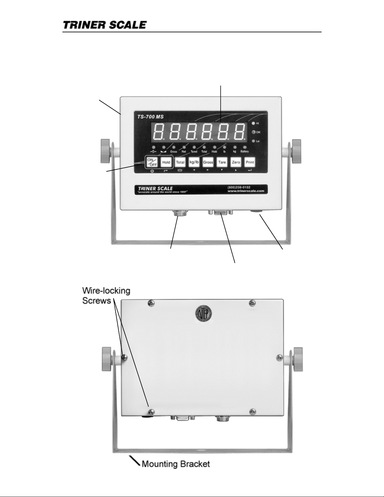
User&s Guide | TS-700 MS
3
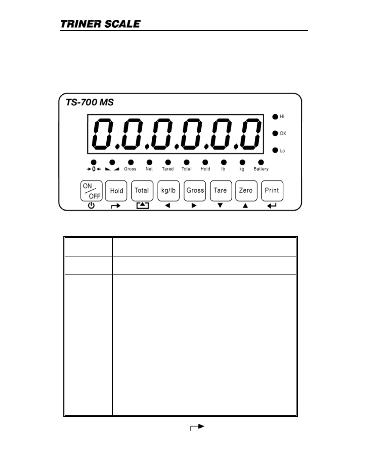
OVERVIEW
Keypad
Digital Readout/Display
Enclosure
Weighing Platform Quick Connect Socket AC Adapter Socket
RS232 DB9 Socket (Printer, PC, Remote Display)
Page 6
User&s Guide | TS-700 MS
4
Operation
KEYS AND THEIR FUNCTIONS
KEY OPERATION / FUNCTION
On/Off Press and hold for 2+ seconds to operate.
Hold
To Hold Weight on Scale (manual hold):
With weight on scale, press Hold key.
To Hold Peak Weight of Multiple Weighings
(auto hold)*:
To enable, press Hold key before loading scale.
To Hold Weight of an Unstable Load (auto
hold)*:
To enable, press hold key before loading scale.
To Release the Hold Function:
Press hold key again to return to normal
operation.
*requires adjustment of parameter #11
Page 7
!!!!!!!!!!!!!!!!!!!!!!!!!!!!!!"#$%&#!'()*$!+!,-./00!1-!!!!!!!!!!!!
!
!!
!
2
!
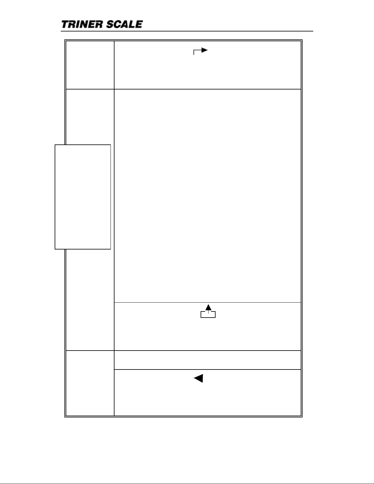
In settings mode:!
3$4(%5!6$7!! !
.!8%$9):(#!
.!8%$##$*!;)4<!:4<$%!=$7>#?!@:%!@(5A4):5#B!
To Add Weights:!
C)4<!;$)D<4!:5!#AEF$G!H%$##!4<$!,:4EF!=$7!4:!
HFEA$!;$)D<4!E5*!A:(54!)5!I$I:%7B!3$I:9$!
;$)D<4G!HFEA$!5$J4!)4$I!:5!#AEF$G!H%$##!,:4EF!4:!
E**!;$)D<4!4:!4:4EF!;$)D<4!E5*!4:4EF!A:(54B!
To View Totals:!
8%$##!,:4EF!E5*!8%)54!=$7!E4!4<$!#EI$!4)I$B!,<$!
4:4EF!;$)D<4!;)FF!@FE#<!A:54)5(:(#F7B!
To go out of view totals mode:!!
8%$##!E5*!<:F*!4<$!,:4EF!=$7B!KLF%!!5M!;)FF!
*)#HFE7B!!
N@!7:(!;)#<!4:!A:54)5($!E**)5D!4:!4<$!4:4EF#G!
H%$##!4<$!8%)54!4:!EAA$H4!4<$!KLF$E%.O:M!H%:IH4B!
L:54)5($!;$)D<)5D!E5*!E**)5D!)4$I#!E#!
%$P()%$*B!
To Clear the Totals Memory:!
8%$##!4<$!Q$%:R"H!S%%:;!=$7!4:!A<E5D$!4<$!!
KLF%!!5M!*)#HFE7!4:!KLF%!!7MB!8%$##!4<$!8%)54!=$7!4:!
EAA$H4!4<$!KLF$E%.T$#M!H%:IH4B!
Total
In settings mode:!
8%$9):(#RU:I$!6$7!! !
V)%#4!H%$##!W!H%$9):(#!
-$A:5*!H%$##!W!<:I$!
8%$##!4:!A<E5D$!H:(5*#R=)F:D%EI#!kg/lb
In settings mode:!
X$@4!E%%:;!=$7!! !
8%$##!4:!I:9$!EA4)9$!*)D)4!:5$!(5)4!:9$%!4:!4<$!
F$@4!
NOTE:
,:!H%)54!
4:4EF#G!H%$##!
E5*!<:F*!4<$!
8%)54!=$7!@:%!
Y!#$A:5*#!
;<)F$!)5!
Z)$;!,:4EF#!
I:*$!
>%$P()%$#!
:H4):5EF!
H%)54$%?B
!
Page 8
User&s Guide | TS-700 MS
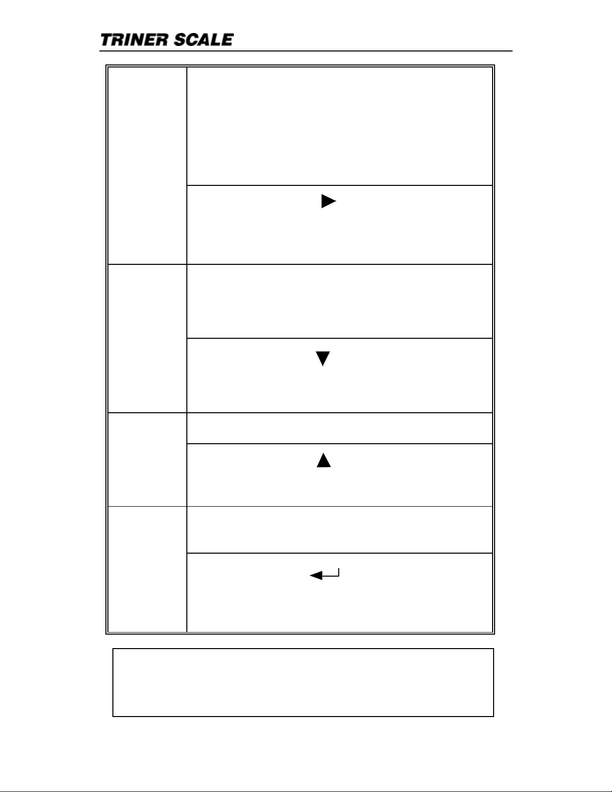
6
For use after a TARE weight has been stored in
the indicator. Press key to toggle view between
gross and net weight.
PLEASE NOTE that there may be a momentary
pause in the display when going from gross to
tare weight.
Gross
In settings mode:
Right arrow key
Press to move active digit one unit over to the
right
With weight on the scale, press to Tare the
weight.
Press again to remove Tare weight.
Tare
In settings mode:
Down arrow key
Press to reduce value of active (flashing) digit.
Press key to zero the scale. Zero
In settings mode:
Up arrow key
Press to increase value of active (flashing) digit.
Press key to print a ticket (requires optional
printer).
Print
In settings mode:
Enter key
Press to accept entry
Press with other keys for functions
IF EQUIPPED WITH INTERNAL RECHARGEABLE
BATTERY: Fully charge the battery for 18 hours before
operating on battery power.
Page 9

User&s Guide | TS-700 MS
7
Load Cell Connections
The indicator can connect with a maximum of
eight (8) 350 load cells, 4 wire or 6 wire
configurations.
Excitation voltage for the load cell is 5VDC, the
maximum output current is 120mA.
Quick Connect Pins
Page 10
User&s Guide | TS-700 MS
8
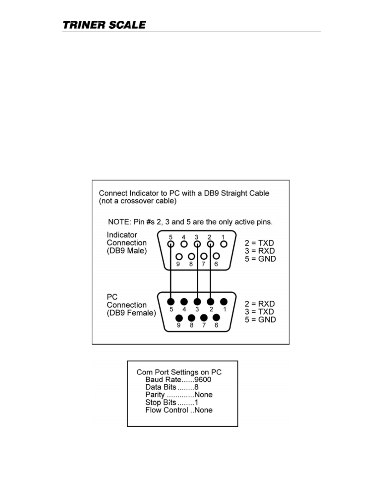
Serial Port Connection
RS232 CONNECTOR
The serial port connector is for attaching a
peripheral device such as a printer or remote
display, or for connecting the indicator to a PC.
NOTE: PC interface requires specific
software to be installed on the PC.
Output to PC
Page 11
!!!!!!!!!!!!!!!!!!!!!!!!!!!!!!"#$%&#!'()*$!+!,-./00!1-!!!!!!!!!!!!
!
!!
!
2
Parameters and Settings
CAUTION3!"#$!45%$!67$8!544$##)89!58*!
5*:(#;)89!<=(%!)8*)45;=%&#!>5%5?$;$%#@!
-$A$%5B!>5%5?$;$%#!458!C$!544$##$*!;75;D!
)E!5B;$%$*D!6)BB!47589$!<=(%!)8*)45;=%&#!
=>$%5;)=8#@!
TO ACCESS AND ADJUST THE TS-700 MS
PARAMETERS:
F%$##!;7$!FGHI,!58*!JKLM!N$<#@!OPQ!6)BB!
*)#>B5<@!G$B$5#$!;7$!N$<#@!OP0RQ!6)BB!*)#>B5<D!
6);7!;7$!R!EB5#7)89@!,7$!*)9);!EB5#7)89!)#!;7$!
54;)A$!*)9);D!58*!458!C$!5*:(#;$*!(>!=%!*=68S!C<!
(#)89!;7$!TUGKV"F!WGGKX!=%!,WGUVMKXI!
WGGKX!N$<@!"#$!;7$!Y'.LZVLU[,!WGGKX!
N$<!58*!;7$!,WGUVGH'J,!WGGKX!YU\!;=!
47589$!67)47!(8);#!*)9);!)#!54;)A$!]EB5#7)89^@!
*TIP3!F5%5?$;$%#!P0_!;7%=(97!P0/!5%$!
B=4N$*!=(;D!58*!5%$!=8B<!544$##)CB$!C<!
#45B$!;$478)4)58!*(%)89!45B)C%5;)=8@!
I5A)95;$!;=!;7$!#$;;)89!>5%5?$;$%!<=(!6)#7!;=!5*:(#;!
58*!(#$!;7$!5%%=6!N$<#!;=!47589$!;7$!#$;;)89#!
A5B($#@!F%$##!;7$!FGHI,!]!!!!!!!^!N$<!;=!544$>;!<=(%!
#$;;)89#D!;7$8!>%$##!;7$!,K,WL!]!!!!!!!!^!N$<!;=!$`);@!
EXAMPLE: ,=!5*:(#;!;7$!*5;$!#$;;)89!)8!
>5%5?$;$%!P_a3
X);7!OP0RQ!EB5#7)89D!(#$!;7$!B$E;!5%%=6!N$<!
47589$!;7$!54;)A$!*)9);!E%=?!;7$!R!;=!;7$!0!
];7$!0!6)BB!EB5#7^@!
"#$!;7$!(>!5%%=6!N$<!;=!)84%$5#$!;7$!0!!
;=!_@!
Page 12
User&s Guide | TS-700 MS
10
Use the right arrow key to move the active
digit from the 1 to the 8 (the 8 will flash).
Use the down arrow key to reduce the 8 to
6 (C16 will display).
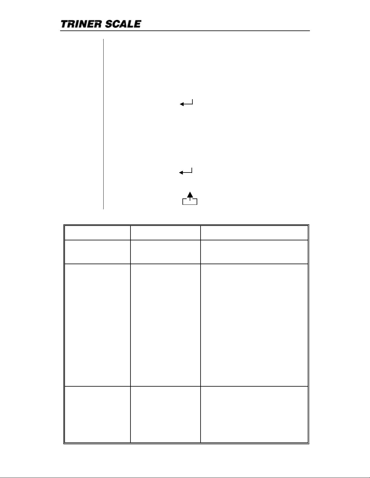
Press the PRINT ( ) key.
The display will show digits for month, day
and year. Use the arrow keys as
discussed above to navigate to and
change the digits.
Press the PRINT ( ) key to accept your
settings.
Press the TOTAL ( ) key to exit.
PARAMETER FUNCTION OPTIONS
C08
Warning tone 0 = no warning tone
1 = warning tone on
C09
Automatic
Power-off
0 = no auto power off
10 = power off
automatically if no
change within 10
minutes.
30 = power off
automatically if no
change within 30
minutes.
60 = power off
automatically if no
change within 60
minutes.
C10
Power saving
setting
(display
backlight on/off)
0 = no power saving
setting
3 = close display if no
change within 3min.
5 = close display if no
Page 13

User&s Guide | TS-700 MS
11
C11
Hold function 0 = no hold function
1 = hold peak weight
2 = hold weight on scale
3 = hold animal weight
4 = reserved
Note: hold peak weight
shows the max. load of
multiple weighings.
C12
Kg/lb
conversion
0 = kg/lb conversion
disabled
1 = kg/lb conversion
enabled
C13
Upper/lower
limit alarm
C14
Lower limit
alarm value
Enter numeric values for
upper and lower
checkweighing limits.
C15
Inner Code
display
Enter C15 to check the
inner code.
C16 Date Set the date, from left to
right: year/month/day
C17 Time Set the time from left to
right: hour/min./sec.
C18
Communication
setting
(Serial interface
data output
method)
0 = Close serial interface
data output
1 = Continuous sending,
connect big display
2 = Print key sends data to
printer or PC.
3 = PC command request
(DataLogPC software)
4 = PC continuous
sending.
5 = Remote display
continuous sending
format.
C19
Baud rate 0 = 1200 1 = 2400
2
=
4800
3 =
9600
Page 14

User&s Guide | TS-700 MS
12
C20
CAUTION:
Changing
these
parameters will
affect the
indicator5s
performance.
Zero range
(amount that
can be zeroed
out with the
Zero key)
0 = disable manual zero
setting
1 = ±1% max capacity
2 = ±2% max capacity
4 = ±4% max capacity
10 = ±10% max capacity
20 = ±20% max capacity
100 = ±100% max capacity
C21
Zero range at
power-up
0 = no initial zero setting
1 = ±1% max capacity
2 = ±2% max capacity
5 = ±5% max capacity
10 = ±10% max capacity
20 = ±20% max capacity
C22
CAUTION:
Changing
these
parameters will
effect the
indicator5s
performance.
Automatic Zero:
tracking range
0 = disable zero tracking
0.5 = ±0.5d
1.0 = ±1.0d
2.0 = ±2.0d
3.0 = ±3.0d
4.0 = ±4.0d
5.0 = ±5.0d
Note:
! d = division
! The zero tracking range
cannot be more than
manual zero range.
C23
Automatic
Zero; tracking
time
0 = disable zero tracking
time
1 = 1 second
2 = 2 seconds
3 = 3 seconds
C24
CAUTION:
Changing
these
parameters will
effect the
indicator5s
performance.
Overload range 00 = close overload range
01d -- 99d
(d = division)
Page 15
User&s Guide | TS-700 MS
13
C25
Negative display
0 = -9d
10 = 10% max. capacity
20 = 20% max. capacity
50 = 50% max. capacity
100 = 100% max. capacity
C26
CAUTION:
Changing
these
parameters will
affect the
indicator5s
performance.
Standstill time
0 = quick
1 = medium
2 = slow
C27
Standstill range 1 = 1d 2 = 2d
5 = 5d 10 = 10d
(d = division)
C28
CAUTION:
Changing
these
parameters will
affect the
indicator5s
performance.
Digital filter
To compensate
for unstable
loads on the
weighing
platform (for
example, animal
weighing).
0 = close dynamic filter
1 = 1 digital filter strength
2 = 2 digital filter strength
3 = 3 digital filter strength
4 = 4 digital filter strength
5 = 5 digital filter strength
6 = 6 digital filter strength
C29
CAUTION:
Changing
these
parameters will
affect the
indicator5s
performance.
Noise filter 0 = disable noise filter
1 = 1 digital filter strength
2 = 2 digital filter strength
3 = 3 digital filter strength
C30 Format of date
print out
0 = yy.mm.dd
1 = mm.dd.yyyy
2 = dd.mm.yyyy
3 = yyyy.mm.dd
C31
Analog output
setting
0 = 0~5Vouput
1 = 4~20mA output
Page 16

User&s Guide | TS-700 MS
14
C32 RESERVED
-------
C33
Relay output
setting
(optional)
0 = Close relay output
1 = Open relay output
function 1
2 = Open relay output
function 2
3 = Reserved menu
C34
RESERVED
-------
C35
RESERVED
--------
C36
CAUTION:
Changing
these
parameters will
affect the
indicator5s
performance.
Gravity of
calibration
location
(Only available
to technician
during
calibration)
C36 = 9.7000 -- 9.9999
C37
CAUTION:
Changing
these
parameters will
affect the
indicator5s
performance.
Gravity of
destination
(Only available
to technician
during
calibration)
C37 = 9.7000 -- 9.9999
C38 Reserved
-------
TIP: When in parameter settings
mode, you can move forward through
all parameters and view the settings by
pressing the PRINT (
) key
repeatedly
.
Page 17

User&s Guide | TS-700 MS
15
Data Output Formats
REMOTE DISPLAY FORMAT
State A
Bits: 0,1,2
0 1 2
Decimal point
position
1 0 0 XXXXXX0
0 1 0 XXXXXXX
1 1 0 XXXXX-X
0 0 1 XXXX-XX
1 0 1 XXX-XXX
Bits: 3,4 Division
0 1 X1
1 0 X2
State B
BITS FUNCTION
Bits0 Gross = 0, net=1
Bits1 Symbol: positive = 0,negative =1
Bits2 Overload (or under zero)=1
Bits3 Dynamic = 1
Bits4 Unit: lb=0, kg=1
Bits5 Constant 1
Bits6 Constant 0
Page 18

!!!!!!!!!!!!!!!!!!!!!!!!!!!!!!"#$%&#!'()*$!+!,-./00!1-!!!!!!!!!!!
!!
!!
!
23
State C
Bit2 4)52! 4)50! (6)5!
0 0! 0! 78!9%!:;!
0 0! 2! 8!
0 2! 0! 5!
4)5!<! =%)65)68>2!
4)5!?!
@A5$6*!
*)#=:BC>2!
4)5!D!
E96#5B65!
2!
4)5!3!
E96#5B65!
0!
PC COMPUTER CONTINUOUS SENDING FORMAT
, ,
CR L
F
S 1 S 2 S 3 Data S 4
-2F!! G$)8H5!#5B5(#F!
-,!>!#5B6*#5)::!
"-!>!695!#5B6*#5)::!
IJ!>!9K$%:9B*!!
-LF!! G$)8H5!M9*$F!
'-!>!8%9##!M9*$!
N,!>!6$5!M9*$!
-<F!! G$)8H5!9O!=9#)5)K$!B6*!6$8B5)K$P!!
!!!!!!!!!!!!QRS!9%!S!TQ!
-?F!! QU8S!9%!Q:;S!
VB5BF!! G$)8H5!KB:($P!)6W:(*)68!*$W)MB:!=9)65!
EXF!! EB%%)B8$!%$5(%6!
JYF!!! J)6$!O$$*!
!
Page 19

User&s Guide | TS-700 MS
17
SERIAL INTERFACE RECEPTION COMMAND
RS232COM serial interface can receive simple
ASCII command.
Command word and role as follows:
Command Name Function
T TARE Save and clear tare
Z ZERO Zero gross weight
P PRINT Print the weight
R G.W/N.W Read gross weight or net weight
C Kg/lb Kg/lb conversion
G G.W Check gross weight at net weight mode
Data Format
Print Format
ID.NO...................004 (Serial No.)
Date:....................XX.XX. XX (yy.mm.dd)
Time:....................XX.XX.XX (hh.mm.ss)
GROSS................NNNNNN lb/kg
TARE...................NNNNNN lb/kg
NET .....................NNNNNN lb/kg
Page 20

!!!!!!!!!!!!!!!!!!!!!!!!!!!!!!"#$%&#!'()*$!+!,-./00!1-!!!!!!!!!!!
!!
!!
!
23
Using A Receipt Printer!
!
!
!
!
!
!
!
!
!
!
!
,4!5%)67!%$8$)57#!9)7:!;6!457)46;<!5%)67$%=!
-!>)7:!549$%!4??@!;77;8:!7:$!5%)67$%!
8;A<$!74!7:$!8466$874%!#48B$7!46!7:$!
(6*$%#)*$!4?!7:$!)6*)8;74%C!
-!D49$%!46!7:$!5%)67$%!E!)6*)8;74%C!
-!D<;8$!9$)F:7!46!7:$!#8;<$!;6*!5%$##!
7:$!D%)67!B$GC!
-!H?!%$8$)57!*4$#!647!5%)67@!#$77)6F#!I;G!
6$$*!74!A$!;*J(#7$*!)6!5;%;I$7$%#!
K23!E!K2LC!!!
-!,4!;*J(#7!7:$!?4%I;7!4?!:49!7:$!*;7$!
5%)67#@!#$$!457)46#!)6!5;%;I$7$%!KM0C!
K;A<$!74!>$)F:)6F!D<;7?4%I!!!!!!
!! ! !
D%)67$%!K466$874%!!!!!!!!!!!!
,G5)8;<!%$8$)57
!
D%)67!N$G!
Page 21

User&s Guide | TS-700 MS
19
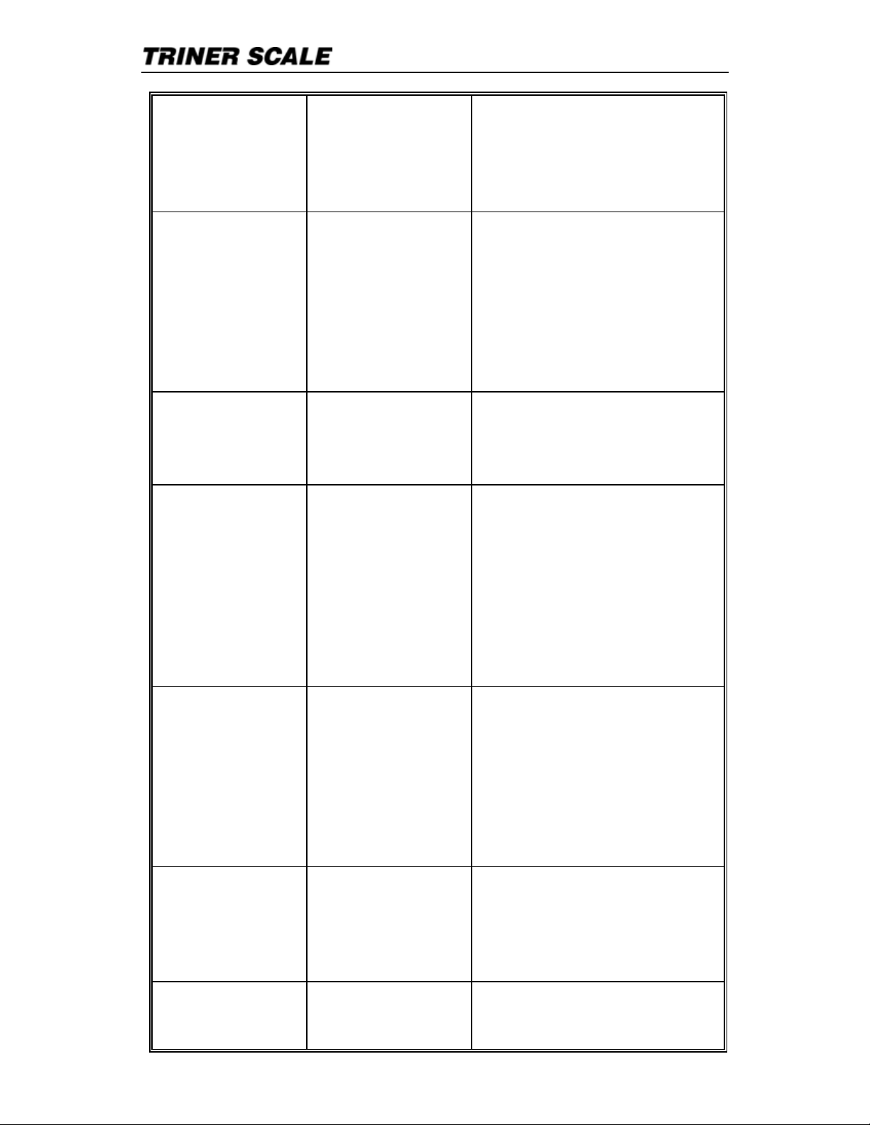
Error Codes
ERROR CAUSE SOLUTION
uuuuuu
1. Overloaded condition.
2. Wrong connection at
load cell.
3. Load cell has quality
problem.
1. Reduce the weight.
2. Check load cell
connection
3. Inspect load cell.
Check the input
and output.
nnnnnn
1. Calibration is incorrect.
2. Bad connections.
3. Load cell has quality
problem
.
1. Check scale is
resisted or not, foot
is kept level or not.
2. Check load cell
connection.
3. Check input and
output resistance of
load cell.
ERR1
Overweight calibration
error.
Incorrect weight input or
incorrect weight on
weighing platform.
1. Input weight
correctly during
calibration.
2. Place correct
weight on weighing
platform.
ERR2
Underweight calibration
error.
Incorrect weight input or
incorrect weight on
weighing platform.
The calibration
weights Minimum is
10% of Max. cap.
Recommend 60%80% of Max. Cap.
ERR3
During calibration, the
input signal is negative.
Check all
connections.
Check load cell.
If connections and
load cell are okay,
PCB needs
replacing.
ERR4
During calibration, the
signal is unstable.
After the platform is
stable, start
calibration.
ERR5 Circuitry error Replace the PCB.
Page 22

User&s Guide | TS-700 MS
20
Factory Default Settings
PARAMETER INSTRUCTION DEFAULT
C01
Calibration
1
C02
Decimal digits
0
C03
Resolution
1
C04
Max. capacity
10000
C05
Empty calibration
0
C06
Capacity calibration
0
C07
Restore default
0
C08
Warning tone
1
C09
Power-off automatically
0
C10
Power saving mode
0
C11
Hold function
0
C12 Disable kg/lb conversion 1
C13 Upper limit alarm 000000
C14 Under limit alarm 000000
C15 Inner code ----
C16 Date setting ----
C17 Time setting ----
C18 Serial interface data
output
0
C19 Serial interface Baud rate 3(9600)
C20 Zero manually 10
C21 Initial zero 10
C22 Zero tracking range 0
Page 23

User&s Guide | TS-700 MS
21
C23 Zero tracking time 1
C24 Overload range 9
C25 Negative range 10
C26 Standstill time 1
C27 Standstill range 2
C28 Dynamic filter 0
C29 Noise filter 2
C30 Print format 0
C31 Analog signal options 1
C32 4~20mA testing 4
C33 Relay output setting 1
C34 Reserved 0
C35 Reserved 6
C36 Calibration location gravity 9.7936
C37 Destination gravity 9.7936
C38 Version No. check ---C39 Reserved menu ----
Page 24

Triner Scale & Manufacturing Co. Inc.
8411 Hacks Cross Road
Olive Branch, MS 38654
(800) 238-0152
www.trinerscale.com
 Loading...