

Page 1
Calibration & Connectivity
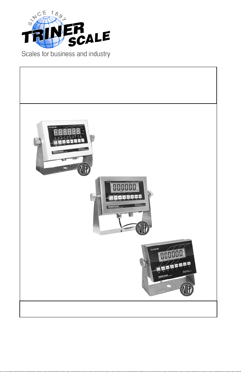
TS-700 Series Digital Indicators
This document supplements the User’s Guide
TS-700 MS
Full Function/Advanced Function Digital Indicator
Version 4.0
TS-700 SS
www.trinerscale.com
TS-700 WB
Page 2

Triner Scale & Mfg.Co., Inc.
8411 Hacks Cross Road
Olive Branch, M S 38654
(800) 238- 0152
www.trinerscale.com
© 2013 Triner Scale. Al l rights reserv ed.
Page 3
Calibration & Connectivity | TS-700 Series
Table of Contents
Specifications...................................................2
Load Cell Connections .....................................3
Serial Port Connections ................................... 4
Calibrating a TS-700 Series Indicator...............6
Data Output Formats .....................................12
Error Codes ...................................................15
Factory Defa ult Sett ings.................................16
!!!! CALIBRATION WARNING !!!!
Calibrati on AND inspec t ion of calibration properties
is prohibit ed unless don e s o by
a qualified s c ale technician.
WARNING
The indicator has stat ic s ens it iv e
components.
Do not make any connections without
powering of f t he indicator.
1
Page 4
Calibration & Connectivity | TS-700 Series
Specifications
TECHNICAL PARAMETERS
Resolution ...................... Display: 30,000
ADC................................ 2,000,000
Zero stability error ........... TK
Span stability error .......... TK
Sensitivity (internal)......... 0. 3 μV /d
Input voltage ................... -30~30mV DC
Excitation circuit.............. 5 VDC
Load Cell Max................. 8, 350Ω
AC power........................ AC100~250V
Operation temp............... - 10 °C ~ + 40 °C
Operation humidity.......... ≤90% RH
Storage temp .................. - 40 °C ~ + 70 °C
NTEP CLASS III............. COC# 09-080
KEYPAD KEYS FUNCTIONS
< 0.1μV//K
0
< ± 6 ppm//K
spn
Hold Hold weight on scale, or Hold peak weight*,
or Hold unstable/animal weight*
Total Total Weight: total of multiple weighings
Kg/lb Display weight in pounds or kilograms
Gross/
Tare
Tare container weight, display gross or net
weight
Zero Returns the indicated weight to “0”
Print Prints receipt (requires optional printer)
PC connectivity (requires PC software)
*requires adjustment of parameter settings
2
Page 5
Calibration & Connectivity | TS-700 Series
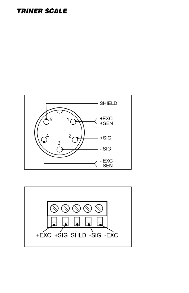
Load Cell Connections
The indicator can con nec t with a maxi mu m of
eight (8) 350Ω load cells, 4 wire or 6 wire
configurations.
Excitation voltage for the load cell is 5VDC, the
maximum output current is 120mA.
TS-700MS/WB Load Quic k- Con nect Pins
TS-700 SS Load C ell Ter minal Block
3
Page 6
Calibration & Connectivity | TS-700 Series
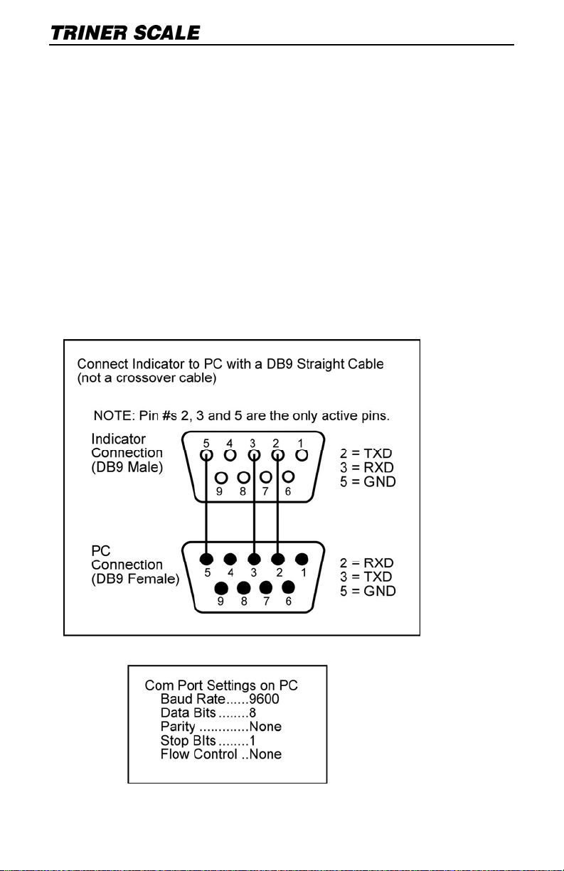
Serial Port Connection
RS232 CONNECTION
TS-700 MS
The RS23 2 DB9 serial p ort c an be utilized to
connect t he indicator to a periphera l dev ice such
as a printer or remote display, or to interface the
indicator with a PC.
NOTE: PC interf ac e requires Tri ner DataLo g
PC™ software to be installed on t he PC.
Indicator t o PC Connect ion
4
Page 7

Calibration & Connectivity | TS-700 Series
TS-700 SS
The 3-wire terminal bloc k located on the main
board can be utilized to connect the indicator to
a peripher al device suc h as a printer or remote
display, or t o int erface the indicator with a PC.
NOTE: PC interf ac e requires Tri ner DataLog
PC™ software to be installed on t he PC.
TS-700 SS RS-2 32 Ter minal Block
TS-700 WB
The RS23 2 3-pin quick-connect serial port can
be utilized to c onnect the indicator to a
peripher al device suc h as a pr inter or remote
display, or to interface the indicator with a PC.
NOTE: PC interf ac e requires Tri ner DataLog
PC™ software to be installed on t he PC.
5
Page 8

Calibration & Connectivity | TS-700 Series
Calibrating a TS-700 Series Indicator
NOTICE: The TS-700 SS/MS/WB are
NTEP Class III Legal for Trade a pproved
and certified. Unlocki ng t he calibrat ion
paramet ers is not allowed by persons
other than qualified scale technicians.
DEFAULT SETTINGS CAUTION
Placing the indicator in calibration mode enables
access to the Default Settings Parameter, CO7.
NEVER activate Parameter C07 unless you are a
qualified scale technician, and:
A) You understand that all custom settings will be
deleted permanently, and
B) You understand how to restore all custom
parameters to the required settings based on the
scale’s specifications and usage.
ALL MO DE L S: Place the Indicator i n
Calibration Mode and Determine if the
Calibration Parameters are Accessible
1) Power on t he indicator.
2) Press the PRINT and H OLD keys. “C ” w ill
display. Release the keys.
3) If the calib rat ion parameters are acces s ible,
“C01” will display, with the 1 flashin g. Proceed
to page 8, “ CA LI BRATION PROCEDUR E”.
NOTE: If C08 Disp lay s ins tead of C01, t he
calibration switch must be adjusted. Disconnect
the AC ada pt er and power of f t he indicator.
6
Page 9

Calibration & Connectivity | TS-700 Series
Calibration Switch, TS-700 MS: Remove the
screws and the back plate of the enc losure. A
white-capped calibrat ion switch is located at the
bottom lef t c orner of the circu it board. Press t he
switch fully in and release. This will place the
switch in the up position, allowing access to the
calibration parameters. Loosely reattach the
rear plate.
Calibration Switch, TS-700 SS: Remove the
screws and the back plate of the enc losure. A
calibration switch is located at the bottom left
corner of the c ircuit boar d. M ov e t he switch to
the “On” pos it ion, allowin g ac c es s t o t he
calibration parameters. Loosely reattach the
rear plate.
Calibration Switch, TS-700 WB: Disconnect all
cables an d c ords. To re m ov e t he back plate of
the enclosure, place the indicator upside dow n
(not face down) on a work s urface. Loc at e t he
two slotted holes near t he c onnection s oc kets.
Insert a flat blade scre wd riv er into each slot
(one at a ti me), pushing th e blade inward while
angled towards the bac k of t he indicator. This
will releas e t he retaining prong and enable
removal of t he back plate. Carefully lift t he rear
plate.
A white-capped calibr at ion switch is loc at ed at
the bottom l ef t c orner of the circ uit board. Pres s
the switch f ully in and release. This will pl ac e
the switch in t he up positio n, allowing access to
the calibration para meters. Loosely reattach t he
rear plate.
ALL MODELS: After enablin g ac c es s t o
7
Page 10

Calibration & Connectivity | TS-700 Series
calibratio n parameters, proceed as f ollows:
CALIBRATION PROCEDURE
1) Power on t he indicator.
2) Press the PRINT and H OLD keys. “C ” w ill
display. Release the keys.
3) “C01” will dis play, with the 1 f lashing. Th e
indicator is now is Parameter Settings mode.
Navigating in Settings Mode
When the indicator is in settings mode, refer to
the graphic printed below the key to det ermine
the keypad key’s function.
The
and arrow keys ar e used to
increase/decrease t he value of the flashing d igit ,
or to navigate up and do w n a lis t of preset
options.
The
and arrow keys ar e used to mov e t he
active digit over to the left or to the right.
The
key and key can be us ed t o move
forward or bac kward through the parameters.
Also, the
key is used to enter/acc ept
changes after they have been made to the
paramet er s et tings.
The
key can be us ed to exit sett ings mode.
With the indicator in set t ings mode and t he
calibratio n weight nea rby , proceed wit h t he
calibration process while referring to the
following chart:
NOTE: After completing and v erif y ing the
calibration, set the calibration switch to the “Off”
position a nd s ecurely fas t en t he rear plate.
8
Page 11

Calibration & Connectivity | TS-700 Series
PARAMETER FUNCTION OPTIONS
C01
C02
Default weighing
unit
1 = kg
2 = lb
Description:
With C01 flashing, press the
key, then use the up or
down arrow keys to change
the parameter setting as
needed.
Press the
the setting and continue on
to the next parameter.
Decimal location 0 = none
1 = one decimal place
2 = two decimal places
3 = three decimal places
Description:
With C02 flashing, press the
key, then use the up or
down arrow keys to change
the parameter setting as
needed.
Press the
the setting and continue on
to the next parameter.
key to accept
key to accept
9
Page 12

Calibration & Connectivity | TS-700 Series
C03
Graduations 1 = one unit
2 = two units
5 = five units
10 = ten units
20 = twenty units
50 = fifty units
Description:
With C03 flashing, press the
key, then use the up or
down arrow keys to change
the parameter setting as
needed.
Press the
the setting a nd continue on
to the next parameter.
C04
Capacity Description:
With C04 flashing, press the
key, then use the left
and right arrow keys to
select the ac tive digit, then
use the up and down keys to
adjust the digits to the
desired capacity, i.e.,
5,000.
Press the
the setting and continue on
to the next parameter.
C05
Zero Calibration 0 = skip zero calibration
1 = proceed with zero
calibration
Description:
With C05 flashing, press the
key, then use the up
arrow key to change the
parameter setting to 1.
Press the
proceed. The zero cal will
count down from 10.
Press the
proceed to the next
parameter.
key to accept
key to accept
key to
key to
10
Page 13

Calibration & Connectivity | TS-700 Series
C06 Calibration 0 = skip calibration
1 = proceed with calibration
Description:
With C06 flashing, press the
key, then use the up
arrow key to change the
parameter setting to 1.
Press the
key to
proceed. “Span” will briefly
display, then all digits will
display.
Load the weighing platfo rm,
then adjust t he displayed
digits to match the weight on
the platform, i.e, 4,000.
Press the
key to
proceed. The indicator will
calibrate, then display
“CalEnd”.
PRESS THE
ACCEP T TH E
CALIBRATION AND EXIT
SETTINGS MODE.
KEY TO
CAUTION -- IMPORTANT NOTICE!!
After ca li br a ti ng , be sur e t o e xit s e tti n gs m o de
without activati ng parameter C07!
Parameter C07 is the parameter that can DELETE all
custom settings and reset the indicator to factory
settings.
C07
CAUTION!!
FACTORY
RESET…
Erases all
custom
settings!
0 = skip reset to factory
defaults
1 = proceed with reset to
defaults
Description:
To reset to factory defaults,
change the 0 setting to 1 and
press the key.
11
Page 14

Calibration & Connectivity | TS-700 Series
Data Output For mats
REM O TE DI S P L AY F O RM AT
State A
Bits: 0,1,2
0 1 2
1 0 0 XXXXXX0
0 1 0 XXXXXXX
1 1 0 XXXXX-X
0 0 1 XXXX-XX
1 0 1 XXX-XXX
Bits: 3,4 Division
0 1 X1
1 0 X2
State B
BITS FUNCTION
Bits0 Gross = 0, net=1
Bits1 Symbol: posit ive = 0,negative =1
Bits2 Overload (or under zero)=1
Bits3 Dynamic = 1
Decimal point
position
Bits4 Unit: lb=0, kg=1
Bits5 Constant 1
Bits6 Constant 0
12
Page 15

Calibration & Connectivity | TS-700 Series
State C
Bit2 Bit1 Bit0 unit
0 0 0 Kg or lb
0 0 1 g
0 1 0 t
Bit 3 printing=1
Bit 4
Bit 5
Bit 6
Extend
display=1
Constant
1
Constant
0
PC COMPUTER CONTINUOUS SENDING FORMAT
, ,
CR L
S 1 S 2 S 3 Data S 4
S1: Weight status :
ST = standst ill
US = not st ands t ill
OL = overload
F
S2: Weight mode:
GS = gross mode
NT = net mode
S3: Weight of positive and negat ive,
“+” or ” –“
S4: “kg” or “lb”
Data: Weight value, includi ng decimal p oint
CR: C arriag e return
LF: Line feed
13
Page 16

Calibration & Connectivity | TS-700 Series
SERIAL INTERFACE RECEPTION COMMAND
RS232C OM serial interf ace can receive simple
ASCII command.
Command word and role as follo ws:
Command Name Function
T TARE Save and clear tare
Z ZERO Zero gross weight
P PRINT Print the weight
R G. W /N.W Read gross weight or net weight
C Kg/lb Kg/lb conversion
G G.W Check gross weight at net weight mode
Data Format
Print Format
ID.NO...................004 (Serial No. )
Date:....................XX.XX. XX (yy.mm.dd)
Time:....................XX.XX.XX (hh.mm.ss)
GROSS................NNNNNN lb/kg
TARE...................NNNNNN lb/kg
NET.....................NNNNNN lb/kg
14
Page 17

Calibration & Connectivity | TS-700 Series
Error Codes
ERROR CAUSE SOLUTION
uuuuuu
nnnnnn
ERR1
ERR2
1. Overloaded conditi on.
2. Wrong connection at
load cell.
3. Load cell has quality
problem.
1. Calibration is incorrect.
2. Bad connections.
3. Load cell has quality
problem
Overweight calibration
error.
Incorrect weight input or
incorrect weight on
weighing platform.
Underweight calibration
error.
Incorrect weight input or
incorrect weight on
weighing platform.
.
1. Reduce the weight.
2. Check load cell
connection
3. Inspect load cell.
Check the input and
output.
1. Check scale is resisted
or not, foot is kept
level or not.
2. Check load cell
connection.
3. Check input and
output resistance of
load cell
1. Input weight correctly
during calibration.
2. Place correct weight
on weighing platform.
The calibration weights
Minimum is 10% of
Max. cap.
Recommend 60 %80% of Max. Cap.
.
During calibration, the
input signal is negative.
ERR3
During calibration, the
ERR4
ERR5 Circuitry error Replace the PCB.
signal is unstable.
15
Check all connections.
Check load cell.
If connections and
load cell are okay,
PCB needs replacing.
After the platform is
stable, start
calibration.
Page 18

Calibration & Connectivity | TS-700 Series
Factory Default Settings
PARAMETER INSTRUCTION DEFAULT
C01
Calibration
1
C02
C03
C04
C05
C06
C07
C08
C09
C10
C11
Decimal digits
Resolution
Max. capacity
Empty calibration
Capacity calibration
Restore default
Warning tone
Power-off automatically
Power saving mode
Hold function
0
1
10000
0
0
0
1
0
0
0
C12 Disable kg/lb conversion 1
C13 Upper limit alarm 000000
C14 Under limit alarm 000000
C15 Inner code ---C16 Date setting ---C17 Time setting ---C18 Serial interface data
0
output
C19 Serial interface Baud rate 3(9600)
C20 Zero manually 10
C21 Initial zero 10
C22 Zero tracking range 0
16
Page 19

Calibration & Connectivity | TS-700 Series
C23 Zero tracking time 1
C24 Overload range 9
C25 Negative range 10
C26 Standstill time 1
C27 Standstill range 2
C28 Dynamic filter 0
C29 Noise filter 2
C30 Print format 0
C31 Analog signal options 1
C32 4~20mA testing 4
C33 Relay output setting 1
C34 Reserved 0
C35 Reserved 6
C36 Calibration location gravity
C37 Destination gravity 9.7936
C38 Version No. check ---C39 Reserved menu ----
9.7936
17
Page 20

Triner Scale & Manufacturing Co. Inc.
8411 Hacks Cross Road
Olive Branch, MS 38654
(800) 238-0152
www.trinerscale.com
 Loading...