

Page 1
“Scales for business and industry since 1897”
(800) 238-0152
Set Up Guide
Axle Scale Model TS60-730AW
INSPECT YOUR SHIPMENT
Pallet #1: Two weighing platforms, stand (if included).
Pallet #2: Four ramps.
Box: Digital indicator, manual and instructions, two
cables, misc. hardware.
Confirm all contents and check for any damage
which may have occurred in shipping.
REQUIRED TOOLS
Forklift.
Hammer drill, 3/4” bit (scale anchors), 1/2” bit
(indicator stand anchors).
Socket wrenches, including 30mm socket for ramps,
or adjustable wrenches.
Screwdrivers: small phillips head, small flat blade.
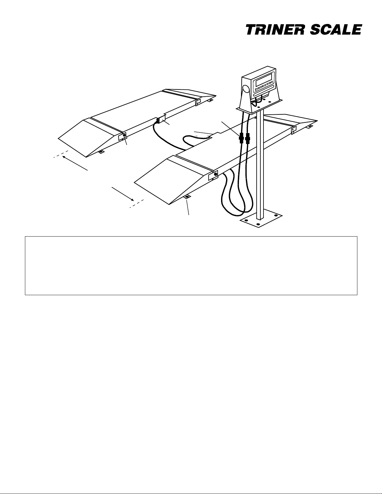
Weighing platform
Ramp
Platform
cables
Indicator stand
(optional)
Digital indicator
Model TS-700 SS
Quick-connectors
Junction boxes
Width of vehicle track
Ramp
connecting
bolt
SET UP THE SCALE
STEP 1: Determine Location of Use
Be sure to select a location that is LEVEL AND
SOLID, such as a thick concrete slab.
Unacceptable surfaces include packed earth,
blacktop, and gravel. Unacceptable surfaces will
give way beneath the weighing platform and result
in inaccurate weighing.
STEP 2: Forklift Platforms Into Position
Unband the platforms pallet. If indicator stand is
included, set aside. With a forklift, pickup one
weighing platform from the shipping pallet. To protect
electronics, be sure to fork from the side of the
platform that does not have the junction box.
Forklift the first platform into position. Refer to the
illustration above: junction boxes should face inward,
and location of digital indicator needs to be taken
into consideration.
Based on the track width of vehicles to be weighed,
place second platform into position. Make sure
platforms DO NOT ROCK from corner to corner.
Remove and set aside the four ramp connecting
bolts from both platforms.
STEP #3: Forklift Ramps Into Position
Place each ramp into position at platform ends.
Securely bolt ramps onto weighing platforms.
STEP# 4: Connect Cables to Junction Boxes
(wiring diagrams are on the back side of this sheet)
Remove both cables from the shipping box. Remove
the cover from one of the platform’s junction box.
Feed the wire leads of one cable into the box through
the available port on the box. Referring to wiring
diagram, connect the five cable wires to the terminal
block labeled “INDICATOR”. Following the same
procedures, connect the second cable to the second
weighing platform. Replace the covers on the
junction boxes.
STEP#5: Connect Platform Cables to Digital
Indicator
Place digital indicator near platforms and connect
both cables from the platforms to the quick-connect
sockets attached to the digital indicator cables.
Ramp
anchor tab
Page 2
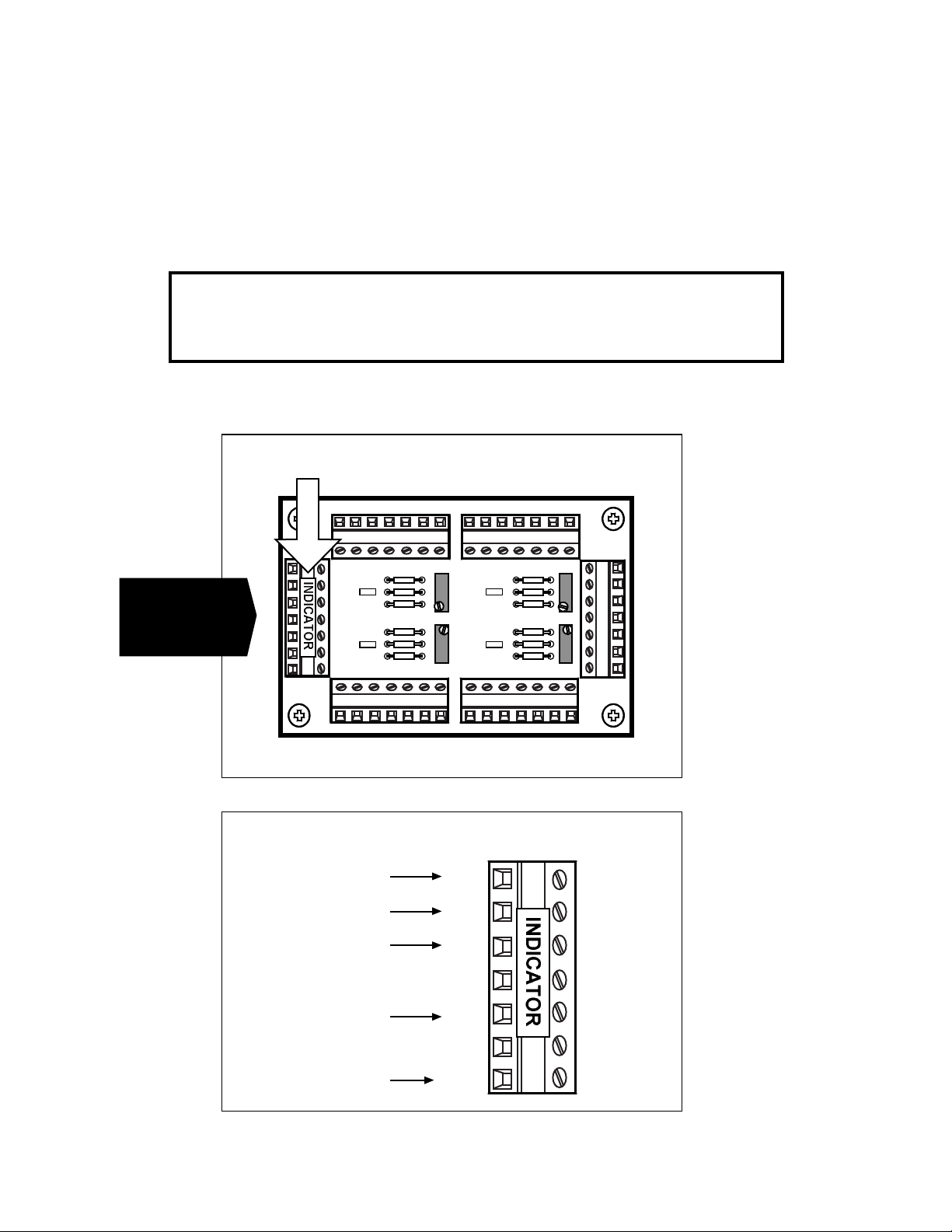
“INDICATOR” label
Terminal block board inside junction box
+IN
-IN
+E
+S
-E
-S
GND
“SHLD” WIRE
Wiring Diagram for Cable Out to Digital Indicator
BLACK WIRE
RED WIRE
WHITE WIRE
GREEN WIRE
STEP 6: Anchor the Ramps and Weighing
Platforms
Using a hammer drill and 3/4” bit, drill anchoring
holes at each ramp anchor tab location. Insert
provided anchor bolts and securely fasten each
anchor.
STEP 7: Anchor the Indicator & Stand (optional)
Using a hammer drill and 1/2” bit, drill anchoring
holes where the stand base is located. Using the
included anchor bolts, securely fasten each anchor.
Using the included bolts, secure the digital indicator
to the stand.
Juncton Box Wiring Diagrams (existing wiring is omitted for clarity))
IMPORTANT NOTE! AVOID DAMAGE TO YOUR SCALE’S CABLES!
To avoid costly damage, be sure to route cables
away from forklift traffic and foot traffic.
Triner Scale & Mfg. Co., Inc. 8411 Hacks Cross Road, Olive Branch MS 381018 (800) 238-0152
For operation of the scale, refer to the digital indicator User’s Guide.
Left Side
Indicator
Connection
Page 3

GND
-S
-E
+S
+E
-IN
+IN
“SHLD” WIRE
BLACK WIRE
RED WIRE
WHITE WIRE
GREEN WIRE
“INDICATOR” label
Terminal block board inside junction box
STEP 6: Anchor the Ramps and Weighing
Platforms
Using a hammer drill and 3/4” bit, drill anchoring
holes at each ramp anchor tab location. Insert
provided anchor bolts and securely fasten each
anchor.
STEP 7: Anchor the Indicator & Stand (optional)
Using a hammer drill and 1/2” bit, drill anchoring
holes where the stand base is located. Using the
included anchor bolts, securely fasten each anchor.
Using the included bolts, secure the digital indicator
to the stand.
Juncton Box Wiring Diagrams (existing wiring is omitted for clarity))
IMPORTANT NOTE! AVOID DAMAGE TO YOUR SCALE’S CABLES!
To avoid costly damage, be sure to route cables
away from forklift traffic and foot traffic.
Triner Scale & Mfg. Co., Inc. 8411 Hacks Cross Road, Olive Branch MS 381018 (800) 238-0152
For operation of the scale, refer to the digital indicator User’s Guide.
Right Side
Indicator
Connection
 Loading...