

Page 1
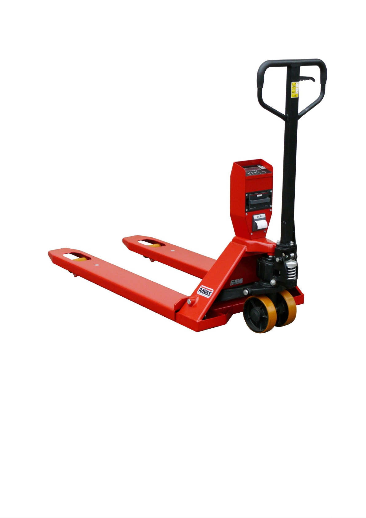
RAVAS-310
OWNERS MANUAL
1
Page 2

OPERATORS MANUAL
RAVAS-310
INDEX PAGE
1. Safety Instructions 3
2. System Setup 4
3. Operation Manual 6
3.1 Using the Weighing Hand Pallet Truck
3.2 Touch Panel Indicator
3.3 Indicator Functions
3.4 Printer (Option)
4. Trouble Shooting 18
5. Spare Parts 21
6. Calibration 23
7. Parameter Settings 25
Contact Us:
RAVAS USA, LLC
975Deerfield Parkway
Buffalo Grove, IL 60089
(224) 676-2238 phone
(224) 676-2136 fax
www.ravasusa.com
info.usa@ravas.com
2
Page 3

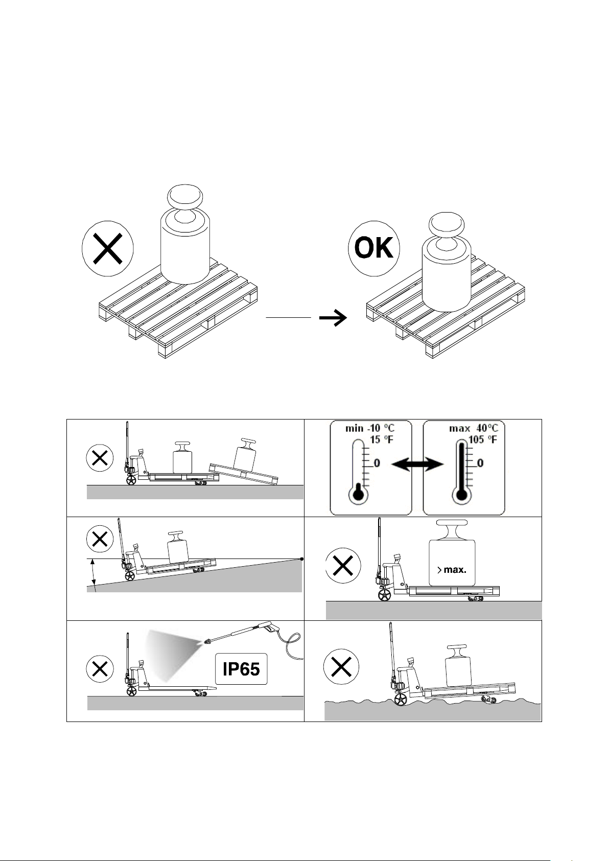
1 SAFETY INSTRUCTIONS
1. NEVER lift a heavy load with just the points of the forks. This could damage the electronic
weighing elements permanently.
2. NEVER weigh without a pallet. This could affect the accuracy of the weighing result.
3. The unit may be loaded with weights up to 5000 lb. However we advise you not to move any
weights above 1650 lb. (750 kg) with the unit. RAVAS is not responsible for injury that may
result when moving heavy loads.
4. Use caution in the vicinity of moving parts - these parts can cut and/or crush hands, arms, feet
and legs.
5. Always center the load you are lifting on both the forks.
6. Do not operate the weighing system on ramps, inclines or declines, without the addition of our
optional parking brake.
7. Do not operate the weighing system while others are on or near the unit. No riding!
8. All modifications must be approved in writing from the supplier, prior to any work being
completed.
9. It is the sole responsibility of the purchaser to train their own employees in the proper use and
maintenance of this equipment.
10. Do not operate this unit unless you have been fully trained of its capabilities.
11. Do not use the weighing system in potentially explosive areas.
12. Do not carry passengers with the truck.
13. Do not weld or make changes to the weighing system without consulting the supplier.
14. Do not lift unstable loads.
15. Check the accuracy of the scale on a regular basis to prevent faulty readings.
16. Only trained and authorized personnel are allowed to operate the truck.
17. Always follow the operating, maintenance and repair instructions of this truck and ask the
supplier when in doubt.
18. Never lower loads if you are unsure you can place the goods on a stable surface. Personal
injury may result from placement on an unstable environment.
19. Always remain with the scale during dosing applications. Incorrect lifting of the pallet can
cause overflowing.
20. RAVAS is not responsible for errors that occur due to incorrect weightings or inaccurate
scales.
3
Page 4
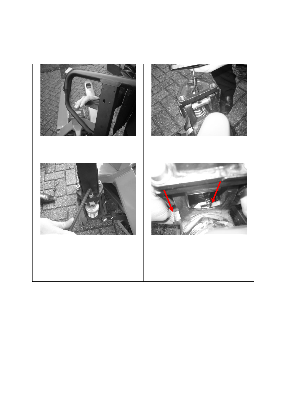
2 SYSTEM SETUP
Make sure the lever is pushed down to
the “pump” position.
Thread the chain through the hole in the
triangle and through the hole in the axle.
Place the handle bar onto the triangle and
insert the bolts.
Tighten the bolts firmly.
Push the silver part “A” on the outside of
the pump downwards.
At the same time; insert the chain into the
open side of the slot “B” on the inside of
the pump.
A
B
MOUNTING THE PUMP HANDLE
4
Page 5

THE BATTERY
The power supply to the system takes place through an exchangeable battery pack.
A completely charged battery should operate for a total weighing time of about 35
hours (on a system without a printer).
When the voltage level of the battery is running low, the display
will show “LO-BA”. When the battery is completely empty, the
weighing system shuts off.
It is necessary to charge the battery for at least 6 hours before the first use.
Recharge battery when the LO-BA indicator comes on.
If you use the system in shift work or if the system has a built-in printer, it is
recommended to purchase a supplementary battery pack.
The battery should be charged on the adapter supplied with the charger. When the
battery is charging, the LED on the charger is lit. When the LED turns off, the battery
is fully charged.
It is not possible to overload the battery because the charger shuts off automatically.
5
Page 6

3 OPERATION MANUAL
INDEX PAGE
3.1 Using the Weighing Hand Pallet Truck 7
Accurate Weighing
Taking the System into Operation
Maintenance
3.2 Touch Panel Indicator 9
The Display
The Touch Panel
Error Messages
3.3 Indicator Functions 12
Graduation
Before Weighing: Check Zero Point
Gross Weighing
Net Weighing: Automatic Tare
Net Weighing: Pre-set Tare
Piece Count: Sampling
Piece Count: Enter a Piece Weight
Summing
Change Units
3.4 Printer (Option) 15
The Print Out
Changing the Thermal Roll Paper
Changing the Date and Time on the Print Out
6
Page 7
3.1 USING THE WEIGHING HAND PALLET TRUCK
-2
Accurate Weighing
The weight must be centered over the forks of the pallet truck and lift freely: without
touching the housing of the indicator or other pallets
Fast temperature changes should be avoided because condensation may form
in the electronics. During acclimatization the indicator must be turned off.
7
Page 8

TAKING THE SYSTEM INTO OPERATION
To activate the scale turn it on using the on/off () button on the terminal.
After 3 to 5 minutes the electronics and load cells have reached the operational
temperature. Before this, inaccuracies of up to 0.3% may occur.
It is recommended not to lift loads before the zero-point correction has been
executed. (See Chapter 5)
MAINTENANCE
The maintenance guidelines for normal pallet trucks apply to the chassis of the
mobile scale. The integrated scale will still function even though the chassis has
been damaged by overloading.
Main guidelines:
- Because the steering wheels are mounted in the front, pulling of the pallet truck is
preferred above pushing it.
- When the lifting mechanism is not used, the handle should be kept in the neutral
(middle) position. This prolongs the life-span of the sealings.
- The scale meets up to the protection class NEMA 4/IP65. This means that dust or
moisture (rain or water beam from all sides), will not influence the operation of the
electronics. However, high-pressure cleansing in combination with warm water or
chemical cleansers will lead to the entry of moisture and have a negative influence
on the operation of the system.
- To avoid damage to load cells and electronics only specialists may undertake any
welding.
- The bearings of the wheels (non-polyurethane) and the pivoting points of the
levelling bar of the loading wheels must be cleansed and greased regularly.
8
Page 9
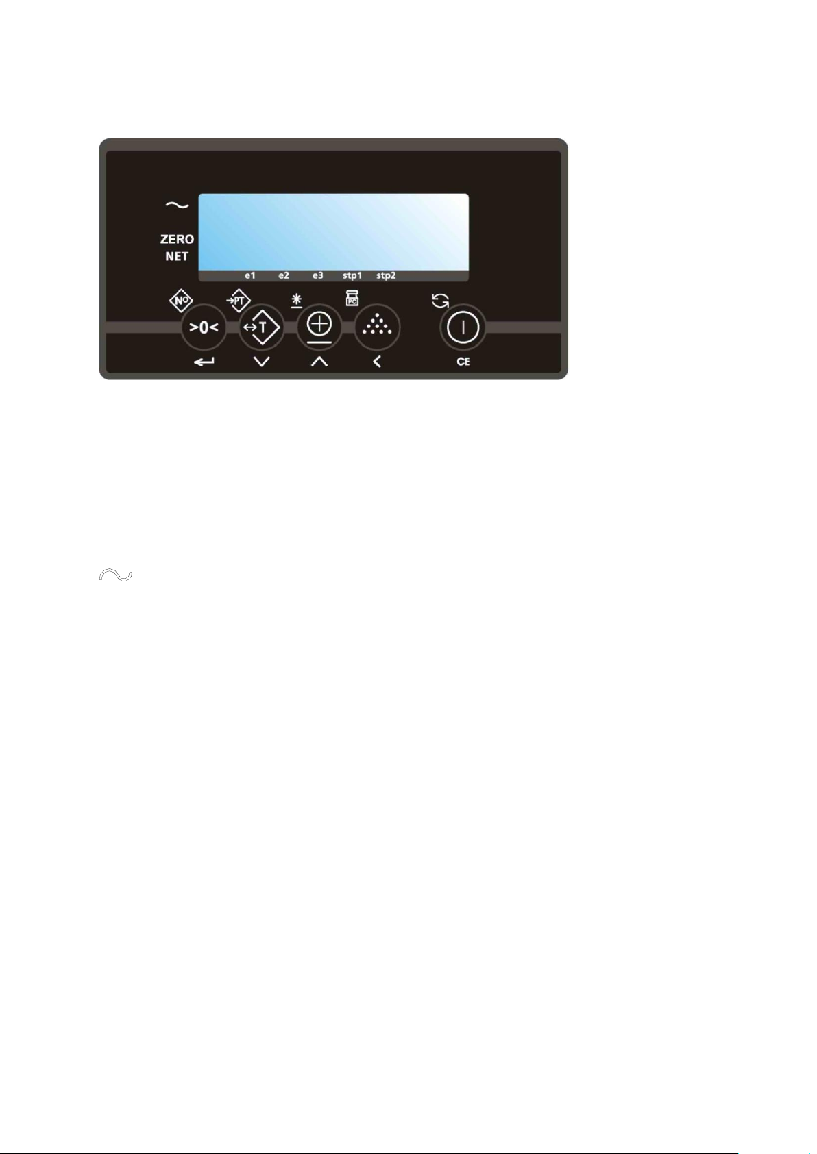
3.2 TOUCH PANEL INDICATOR
Indicator Front
◄
the scale (including load) is stable
▬ the weight shown is negative
ZERO
◄
the weight shown is within the zero range
NET
◄
the display is showing the net weight
e1 ▼ displayed weight shown is in range 1
e2 ▼ displayed weight shown is in range 2
e3 ▼ displayed weight shown is in range 3
stp1
▼
Set-point 1 is activated
stp2
▼
Set-point 2 is activated
There are 3 display-modes: lbs, kg or the number of pieces.
Also the battery sign is integrated in the display in order to show a low battery status.
THE DISPLAY
By means of eight pointer bars the display shows:
9
Page 10

THE TOUCH PANEL
Key
Function level 1
(short key press)
Function level 2
(long key press)
Function level 3
(entry mode)
zero setting
code entry
enter
automatic tare
pre-set tare
decrease the value of
the digit flashing
print weight and add
to the total
check subtotal and
print total
increase the value of
the digit flashing
sampling a piece
weight
enter a piece weight
shift to the next digit
on the left
on/off switch
Change units mode
clear entry
Each key has 2 operational and one entry function
IMPORTANT
Operation of a key is not accepted unless the scale is stable (and the “load stable”
pointer lights up). This means that the indicator only executes commands with a
stable load.
WARNING
When the weighed load surpasses the pre-set maximum the display shows:
“ERR02”. In order to prevent damage to the indicator or load cells, the scale must be
unloaded immediately.
10
Page 11

ERROR MESSAGES
Displayed error
Meaning
Out of error mode
Err01
Load cell signal is unstable
Automatic
Err02
Overload on full scale
Automatic after
removing weight
Err03
Gross negative. This action is not allowed
Automatic
Err04
Out of zero range
Press any key
Err05
Sampling accuracy too low
Press any key
Err06
Input signal too high
Automatic after
correcting input
Err07
Input signal too low
Automatic after
correcting input
Err08
Calibration out of range (negative)
Automatic
Err09
Calibration out of range (signal too low)
Automatic
Err10
Calibration count 2nd(3rd) point lower than
count 1st(2nd) point
Automatic
Err14
Set-point value 2 < set-point value 1. This is
not allowed
Automatic
Err98
Calibration point must be higher than
previous one
Automatic
Err99
Action only allowed in start-up units
Automatic
11
Page 12

3.3 INDICATOR FUNCTIONS
GRADUATION
From 0 to 5000 lbs the weight is shown in 2 lb increments.
BEFORE WEIGHING: CHECK ZERO POINT
Before each weighing it is necessary to check whether the system is unloaded and
free. The indicator is fitted with an automatic zero correction. This means that small
deviations of the zero point will be corrected automatically. If the indicator does not
determine the zero point automatically, it must be done manually by pressing the >0<
key.
GROSS WEIGHING
After lifting a load, the display shows the gross value of the weighed load.
NET WEIGHING: AUTOMATIC TARE
The indicator offers the possibility to reset tare weights to zero automatically. This
way added or subtracted weights can be determined.
Lift load.
Press key T.
The indicator is set to zero.
The "NET" pointer shows that a tare weight is activated.
Place or remove the net load.
The display shows the net value of the weighed load.
When load is removed, a negative weight is displayed.
By pressing the T key again, the gross weight is displayed.
NET WEIGHING: MANUAL TARE ENTRY
A tare weight can be entered at any time, either in a loaded or unloaded situation.
Press the
seconds).
The display shows the current tare value.
The right digit is blinking.
Press ENTER () if the current tare value is correct.
Or
PT key until the display changes and the last digit is blinking (approx 3
12
Page 13

Press the
PT key until the display changes and the last digit is blinking (approx 3
seconds).
The display shows the current tare value.
The right digit is blinking.
Press the
key to go up a value or press the key to go down a value until the
required value is reached for that place.
Press to change to the next digit.
Repeat this procedure until the required tare value is displayed.
Press ENTER () to activate the tare weight.
The tare weight is activated.
The “NET” pointer lights up.
When the system is loaded, the net value appears in the display
When the system is unloaded, the read-out displays the negative value of the
given tare.
The entered value remains active until a new tare weight is entered (display
shows the new net weight).
Press the T key to return to gross weighing mode.
PIECE COUNT: SAMPLING
If an unknown piece weight is to be determined you may do this by sampling a
certain number of pieces. The number of pieces taken from or placed on the scale
determines the accuracy of the sampling. The total weight of the pieces taken from or
placed on the scale for the sampling should be no less than 9-10 lb. The greater the
weight difference, the greater accuracy. The standard sampling amount is 10 pieces,
but this number can be increased up to 95 pieces. (wordy)
Press the key.
The display shows “add10”. The “lb” pointer changes to “pcs”.
Take or place 10 pieces from/on the scale and press the ENTER () key.
The sampling is done and the display will show the total number of pieces on
the scale.
Or
Press the key or the key to change the number of pieces to add.
The display will show the new value to add. (for example “add50”)
Take or place 50 pieces from/on the scale and press the ENTER () key.
The sampling is done and the display will show the total number of pieces on
the scale.
To return to the normal weighing mode press the key for 3 seconds.
PIECE COUNT: ENTER A PIECE WEIGHT
Press the key for 3 seconds.
The last used piece weight will be displayed with the right digit flashing.
To accept the old value press ENTER ().
The display shows the number of pieces currently on the scale.
13
Page 14

Or
Change the piece weight value by using the or and keys.
The display shows the new piece weight.
To accept the new value press ENTER ().
The display shows the number of pieces currently on the scale.
To return to the normal weigh mode press the key.
SUMMING
The indicator offers the possibility to add weighings and show the total weight. When
a tare weight is active, the net weight is added automatically.
Load the system with the weight that should be added.
Press the key to add the weighed load to the total weight.
The display shows the message “ADDED” and after a short delay returns to
the weighing mode.
Note that no weight can be recorded twice. The system needs to be returned to the
net zero-range before another weight can be added up.
To check the subtotal can be checked by pressing the key for 3 seconds.
The display shows the net total weight and the number of weightings totaled
so far repeatedly for 3 seconds.
If the key is pressed during this period, the total is printed out (if option
is installed) and reset to 0.
If the “CE” key is pressed during this period, the total is reset but not
printed out.
If no key is pressed during this period, the subtotal stays in memory and
the system returns to the weighing mode after 60 seconds.
CHANGE UNITS
The system is set to start up in „lbs‟ or in „kg‟. However you may, at any time in the
weighing mode, change to the second unit (lbkg or kglb).
Press the key for 3 seconds.
❏ The display will show the current weight in the new units for 5 seconds and
then automatically change back to the start up units.
Note: The same key is used to change from the piece counting mode back to the
weighing mode.
14
Page 15

3.4 PRINTER (Option)
The RAVAS 310 comes equipped with a thermal printer. Obtained and entered
weighing data can be printed.
THE PRINT OUT
In the printout a gross weight is indicated with the letters “B/G” and a net weight with
the letter “N”. A manually entered tare weight will also be printed and is indicated with
the letters “PT”. The total weight is shown with the letters “TOT”.
Standard print-out Standard print-out
without code with code
B/G 1234.5 lb. CODE 12345
T 34.5 lb. B/G 1234.5 lb.
N 1200.0 lb. T 34.5 lb.
N 1200.0 lb.
Nr. 1
10/07/03 17:45 Nr. 1
10/07/03 17:45
Piece count print-out Piece count print-out
without code with code
B/G 1234.5 lb. CODE 12345
T 34.5 lb. B/G 1234.5 lb.
N 1200.0 lb. T 34.5 lb.
N 1200.0 lb.
PcWt 1.234 lb.
Qty 12345 PCs PcWt 1.234 lb.
Qty 12345 PCs
Nr. 1
10/07/03 17:45 Nr. 1
10/07/03 17:45
Total print-out (always without code)
Tot. B/G 1234.5 lb.
Tot. T 34.5 lb.
Tot. N 1200.0 lb.
Tot. Nr. 999
10/07/03 17:45
15
Page 16

CHANGING THE THERMAL PAPER ROLL
Open the printer cover by pressing down
the 2 levers and pulling the cover towards
you.
Remove the existing paper roll. Position
the new paper roll, making sure it unrolls
in the correct direction, as shown above.
Unroll the paper slightly. Re-close the
cover, holding the edge of the paper.
The printer is now ready for use.
16
Page 17

CHANGING THE TIME AND DATE ON THE PRINT-OUT
The date and time can be printed together with the weight information.
Press the key for 6 seconds.
The display will show “ho_00” or the previous hour time setting, with the right
digit flashing.
To accept the old value press ENTER ().
Or
Press the key to go up a value or press the key to go down a value until the
required value is reached.
Press to change to the next digit and use the or key to change the value until
the required value is reached.
To accept the new value press ENTER ().
The display will show “m_00” or the previous minute time setting, with the right
digit flashing.
Repeat the above procedure to accept or change the minute setting.
The display will show “dA_00” or the previous date of the month setting, with
the right digit flashing.
Repeat the above procedure to accept or change the date of the month setting.
The display will show “m_00” or the previous month setting, with the right digit
flashing.
Repeat the above procedure to accept or change the month setting.
The display will show “YE_00” or the previous year setting, with the right digit
flashing.
Repeat the above procedure to accept or change the year setting.
The indicator will return to normal weighing mode.
17
Page 18

No power
Change
batteries
Replace battery pack
Use a fully charged battery pack. (see page 5)
12Vdc on the
board
Check the board for
burned components
Picture of component most likely to blow when
batteries have been entered the wrong way.
Accuracy
No
repeatability
Check if there is a
mechanical problem.
Load left and right fork with for example body weight
and see if weight changes when you are in different
positions on the scale.
There should not be a difference larger than 2 lb.
If there is a bigger difference then 5 lb you have a
load cell or a mechanical problem.
To make sure it is a mechanical problem, repeat test
with a heavy load on the scale, Lift a pallet with 2000
or 3000 lb.
Reset Indicator for 0 lb using the tare function.
Load corners with body weight by standing on or on
the sides of the pallet. If readings change more than 5
lb you have a mechanical problem.
The push rods in the forks may not interfere with the
load cells. Take of the fork shoe by unscrewing the
nuts on the bottom side of the pallet truck.
Push the pushrods sideways towards the load cells to
see if they come in contact with the load cells: see if
they can interfere with the load cells.
With the forks lifted half way up, the brackets for the
loading wheels may touch the fork shoe. By taking off
the fork shoe, Scratches will show if it does and where
it does.
Check if bolts are loose.
Check the load cells. If
one is broken or gives
more or less signal
than the others, the
scale will give different
reading depending
how it is loaded.
To be sure that it is not a mechanical problem, load
the load cells directly. Take off the fork cover. Try to
apply weight 25 to 50 kg / lb, direct onto each load
cell. If the indicator shows the same reading, the load
cells are OK.
Tap with a hammer onto the load cells. Do not be
afraid to break it. Repeat the test for each load cell.
Measure resistance with ohm meter between wires
and load cell body. Do this with the other load cells
disconnected from indicator. No resistance is allowed.
The load cells should have +/- 350 ohm between the
signal wires: yellow and green, and excitation wires,
black and red.
Check cables
Bad connections will cause changes when moving the
scale.
Bend and move the cable briskly especially where the
cable is moving continuously while lifting. While doing
so, look at the display to see if it reacts to the
movements.
4 TROUBLE SHOOTING
18
Page 19

The potentiometers
with which we
calibrate the output of
the load cells, are
mechanical parts
therefore, higher risk
components
Move the board and but pressure with fingers on the
potentiometers while looking at the display to see if it
reacts. Do not touch the contact itself.
Not linear
Check if it is load cells
or indicator
Load cells or indicator are very rarely the cause of this
problem. Easiest way to check is by changing the
indicator temporarily. If problem is not solved when
changing the indicator, the problem is the load cell,
cable or mechanics
Check cable
Very rarely the cause. Maybe in a lift truck.
Instability
With no load it
is most of the
time humidity,
bad connection
or component r
bad shield.
Check for humidity
Check for water marks on the indicator board or load
cell connections (potentiometers).
Check the indicator.
Sometimes the indicator will show a weight when the
load cells are disconnected. If you do this and the
indicator becomes more stable, it is most likely
elsewhere in the system.
Check visually for traces of oxidation. If found, heating
the solder contacts can solve the problem.
Check cables. In
warehouse and lift
truck the cable is
working all the time
when following the
lifting movement. It
may be worn or
damaged. Changing
temperatures and
chemicals have an
effect on the lifetime of
a cable.
Bad connections will cause changes when moving the
scale.
Bend and move the cable briskly especially where the
cable is moving continuously when lifting. While doing
so, look at the display to see if it reacts to the
movements.
The potentiometers
with which we
calibrate the output of
the load cells are
mechanical parts and
are sensitive to
humidity, shocks and
vibration.
Move the board and but pressure with fingers on the
potentiometers while looking at the display to see if it
reacts. Do not touch the contact itself.
Check the load cells.
If connected independently to the indicator, it can be
checked which one is unstable and which one is not.
With load
Check mechanics.
Function
error
No reaction
when pushing
keys
Check the touch panel
Test can be done by making short cut on connection
of the touch panel to simulate a key being pressed.
Check for wear of broken contacts in the flat cable
going to the indicator board
Lock up
Take out the battery pack and replace to see if it
starts up afterwards.
19
Page 20

Not summing
Operator error
.
Load is not stable.
Scale needs to be unloaded before accepting new
print.
System will not print weights that are smaller than the
graduation.
HELP
messages
HELP 2
Scale is overloaded
Take load from scale. If there is no load do the same
checks as you do with HELP 3 and 7.
Help 3 or 7
Load cell signal too
high or too low.
Check cables for damage. Move the cable while
looking at display to see if indicator reacts.
Measure load cells to see if they are fine.
Check the excitation signal of the indicator
Help 4
Out of zero range
Zero calibration needed.
20
Page 21

5 SPARE PARTS
21
Page 22

SPARE PARTS LIST
Weighing Hand Pallet Truck RAVAS 310
Nr
Article Number
Description
Quantity
1
899193001.3
set fork shoes
1
2
895200708
chassis
1
3
891112256 or
load cell
4
891112255
4
899172200
mounting plate load cell 6 mm
4
5
894141903
load cell mounting bolt (M12 x 35)
8
6
894141922
forkshoe mounting bolt (M12 x 60)
4
7
894142331
forkshoe mounting nut self tightening (M12)
4
8
895201705
handle (black)
1
9
895200780
pump (black)
1
10
895201799
pump repair set
1
11
895201701
steering wheel (polyurethane)
2
12
895201702
loading wheel (polyurethane tandem)
2
13
894141664
indicator support mounting bolt (M8 x 20)
3
30
892131291
touch panel with support plate
1
31
892142545.2
LCD display
1
32
892142545
indicator print board
1
33
892203003
RS232 board indicator
1
34
892203001.1
indicator adaptor bracket
1
35
892203002
indicator mounting support
1
36
894142400
butterfly nut
2
37
899193027.03
steel housing indicator
1
38
893142060
level switch 2° (approved version)
1
39
894207008
enclosure bolt (M5 x 8)
4
40
894203000
screw (KB40 x 8)
6
41
893203004
battery fixation clip
1
42
898202000
charger 230V - 12 V
1
43
893161500
load cell calibration board
1
44
893201006
plastic housing battery module
1
45
983209002
battery connection pins
2
46
893201003
fuse cover
1
47
893143606
fuse 5 x 20mm 2A
1
48
898201000
battery module 12V - 1.2Ah with handle
1
49
892132601
cable for thermal printer
1
50
892132600
thermal printer
1
51
892132604
paper roll for thermal printer
1
52
899193027.33
cover plate
1
22
Page 23

6 CALIBRATION
CALIBRATION INSTRUCTIONS INDICATOR 310
The calibration mode can only be reached from the standard weighing mode. You cannot get into the
calibration mode when you are in piece count mode.
DEFINING ZERO
Unload the system.
Switch the system on.
To enter the zero calibration mode press the >0< key for 10 seconds.
After 3 seconds the display will show the last entered code.
After 7 seconds the display will go into the zero calibration mode and start adjusting.
The display will show “Adj08” and run down until “Adj00”. The adjustment has been
completed.
The indicator shows the percentage of the total capacity that was adjusted. For a normal scale
this would be between 5 and 8 percent. A larger percentage could mean one or more load
cells are broken. A lower percentage could mean the fork cover is not mounted.
The zero point has been defined, the system automatically returns to the standard weighing
mode.
SINGLE POINT CALIBRATION
Press the T key for about 10 seconds.
After 3 seconds the display will show the last entered pre-set tare value.
After 7 seconds the display will go into calibration mode.
The display will show the first calibration point with the pointer “e1” flashing.
Using the and keys you can see the three earlier programmed values on the display.
The pointer will move through e1-3. “e1” is the first calibration point, “e2” the second and “e3”
the third.
When calibrating only one point the second and third values should be set to zero.
Use the and keys to move to the second calibration point.
The display will show the pointer “e2” flashing.
Press the key.
The display will show the previously entered calibration value, with the last segment flashing.
Use the , and keys to return all the segments to zero.
Press the key.
Use the and keys to move to the third calibration point.
Repeat the above to set all the segments to zero.
Press the key.
Calibrating the single point
Use the and keys to return to the first point.
The indicator shows the value of the first calibration point, with the “e1”pointer flashing.
Load the scale with a known weight.
Press the key to enter this weight onto the indicator, the first segment starts flashing.
Use the and keys to change all the segments until the proper weight has been entered.
Press the key to return to calibration mode. The “e1” pointer will start flashing.
Press the key for 3 seconds to confirm the entered weight.
This calibration number counts down from Adj 08 to Adj 00, the first calibration point has now
been set.
Leave the calibration mode by pressing the or key until AP XX appears. This number indicates
the calibration sensitivity percentage, eg AP 07.
Press the key.
The display now shows the value of the gravitation constant. Use the , and keys to
correct this for your position.
Press the key to return to the standard weighing mode.
23
Page 24

MULTI-POINT CALIBRATION
Push the T key for about 10 seconds.
After 3 seconds the display will show the last entered pre-set tare value.
After 7 seconds the display will go into the calibration mode.
The display will show the first calibration point with the pointer “e1” flashing.
Using the and keys you can see the three earlier programmed values on the display. The
pointer will move through e1-3. “e1” is the first calibration point, “e2” the second and “e3” the third.
Use the and keys to return to the first point.
The indicator shows the value of the first calibration point, with the “e1” pointer flashing.
Load the weighing system with a known weight.
Press the key to enter this weight onto the indicator.
The first segment will start flashing.
Use the , and keys to change all segments until the proper weight has been entered.
Press the key to return to calibration mode.
The “e1” pointer will start flashing.
Press the key for 3 to confirm the entered weight.
This calibration number counts down from Adj 08 to Adj 00, the first calibration point has now
been set.
Move to the second calibration point.
The display will show the pointer “e2” flashing.
Repeat the procedure for a second known weight. Be aware that the value of this weight has to be
higher than that of the first weight. If not, the display will show ERR98 and return to the entry
mode for the calibration point.
Repeat the procedure for the third known weight. Leave calibration mode by pressing the or
key until AP XX appears.
This number indicates the calibration sensitivity percentage, eg AP 07.
Press the key.
The display now shows the value of the gravitation constant. Use the , and keys to
correct this for your position.
Press the key to return to the standard weighing mode.
24
Page 25

7 PARAMETER SETTINGS
ATTENTION: Before entering the setup mode make sure that the battery
supply is sufficient. A low battery may cause the micro-processor to block. If
this happens remove the empty battery and replace it with a fully charged
battery. You should be able to start the indicator in the normal way.
To enter the setup mode, turn on the indicator and keep the key pressed for 20
seconds. You will go through the normal start-up routine (all segments on; software
version; calibration number and weight) and end up in the “P_01” with the right digit
flashing.
At this stage you may proceed as follows:
To enter parameter 01 press the key quickly.
o The display will show the setting for this parameter at this moment.
You may change the setting by using the or the key.
OR
You can accept the setting by pressing .
OR
To move to the next parameter you press the key.
OR
To move to the previous parameter you press the key.
To leave the set-up mode you do the following:
With P_XX in the display press the key quickly.
o The display will show “P_00”
Press the key again quickly.
o If a change was made to the settings the display will show “SET__”
briefly and then return to the normal weighing mode. The calibration
number will be increased by every time a change was made in the set
up and also after a new calibration.
o If no change was made, the display will return into the normal weighing
mode.
In the following pages the different parameters are explained and the standard
settings are given. Parameters that are not used yet will not be accessible or
displayed with underscores.
25
Page 26

PARAMETERS:
Parameter
Function
Settings
Default
US
01
Start-up unit (and print units)
1=kg / 2=lb
2
02
Smallest graduation step for
multi-range
0.1/0.2/0.5…………10/20/50
0.5
03
Largest graduation step for
multi-range
0.1/0.2/0.5 ……….. 10/20/50
2
04
Number of graduations for
every range
0000-9900 divisions
1000
05
Weighing capacity system (full
scale)
0000-99999 units
5000
06
Motion tolerance for stable
0-32
1
off 0.5 grad./sec
1 grad./sec 2 grad./sec
4 grad./sec 8 grad./sec
16 grad./sec 32 grad./sec
07
Filter size
0-12
8
0=off
1=light filtering, 12=heavy filtering
08
Auto zero range
0=off 0.5 division
0.5
1=division 3 divisions
09
Zero range positive (+)
0-100% (approved 2%) of span
10
10
Zero range negative (-)
0-100% (approved 2%) of span
10
11
Test Function
BASIC ADC Counts
bASIC
10x Resolution
12-13
Not used
14
Start-up number to add in
sampling mode
1-2-5-10-20-50-95
10
15
Units switch mode active
Yes / No
Yes
16
Setpoint function
0-4
0
0=not used
1=overload gross (only 1 setpoint used)
2=overload gross (only 1 setpoint used)
3=Printer (without date/time/switched supply)
4=not used
17
Application
Basic (standard) or Peakhold (Phold)
bASIC
18
Gravity value working area
9.750-9.850
9.797
19
Key function
Remote - Local - Both
Local
20
Baudrate comport 1
600-1200-2400-4800-9600-19200
9600
21
Databits comport 1
7-8 8 22
Parity comport 1
none/odd/even
none
23
Stopbits comport 1
1-2
1
24 Not used
26
Page 27

25
Dataprotocol comport 1
0-4
0
0=PC bi-directional command structure
1=not used
2=Remote display continuously
3=Printer (without date/time/switched supply)
4=not used
26
Number of linefeeds comport
1
0-9 0 27-29
Not used
30
Baudrate comport 2
600-1200-2400-4800-9600-19200
9600
31
Databits comport 2
7-8 8 32
Parity comport 2
none/odd/even
none
33
Stopbits comport 2
1-2 1 34
Not used
35
Dataprotocol comport 2
0-4 3 0=PC bi-directional command structure
1=not used
2=Remote display continuously
3=Printer (without date/time/switched supply)
4=not used
36
Number of linefeeds comport
2
0-9 5 37
Printout form
0-1
0
0=standard 1=total
38
Printout format time/date
European format dd/mm/yy hh:mm
USA
USA format mm/dd/yy hh:mm
39
Not used
40
Level switch
0=not used 1=N.C. 2=N.O.
0
41
Delay trigger time level switch
0-10 sec.
3
42
Not used
43-49
Not used
50
Battery used
12VDC 6 VDC
12v
51
Low Bat switch off time
0-99 mins
2
0=not switched off
52
Auto shut off time if not used
0-99 mins
15
0= always on
53
Not used
54
Peak hold time
0-7 4 55
threshold value
9999kg/lb
200
56-89
Not used
90
Reset to default parameter
If parameter 01 was on 1 it will default to the
setting without altering
EU settings. If P_01 =2 the US settings will be
calibration parameters
defaulted. New delivered boards will have
EU settings.
27
Page 28

91
Reset to default parameter
If parameter 01 was on 1 it will default to the
settings including calibration
EU settings. If P_01 =2 the US settings will be
parameters
defaulted. New delivered boards will have
EU settings.
92-99
Not used
RAVAS USA, LLC
975 Deerfield Parkway
Buffalo Grove, IL, USA 60089
(224) 676-2238
www.ravasusa.com
Rev. 05.10.10
28
 Loading...