

Page 1
INSTALLATION GUIDE
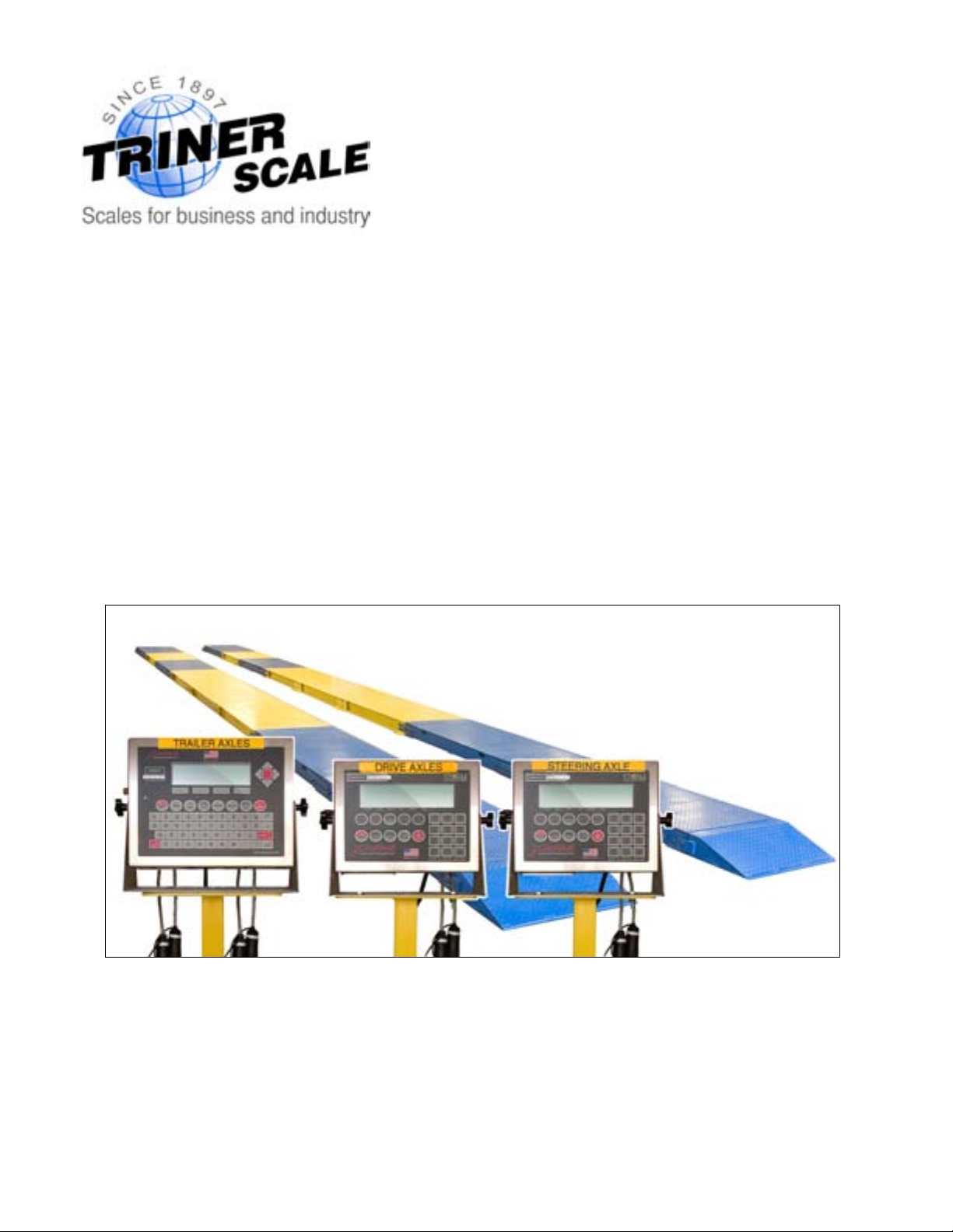
Axle Weighing Truck Scale
60,000 lb x 20 lb
Factory Calibrated
Includes Pre-interfaced Wireless Remote LED Scoreboard Displays
V 1.0
Page 2
Assembly Guide Axle Weighing Truck Scale
2
OVERVIEW
TOOLS REQUIRED
• Forklift and block
• Prybar
• Wrenches: #8 allen wrench, 15/16” & 30mm ratchet or pneumatic wrench
ESTIMATED TIME REQUIRED TO SET UP THE SYSTEM
• 10-12 hrs
RECOMMENDED NUMBER OF PERSONS TO SET UP THE SYSTEM
• Two
ASSEMBLY SYNOPSIS
Assembly of the scale is a very straightforward procedure. Most of the required assembly
time is in positioning the large, heavy platforms.
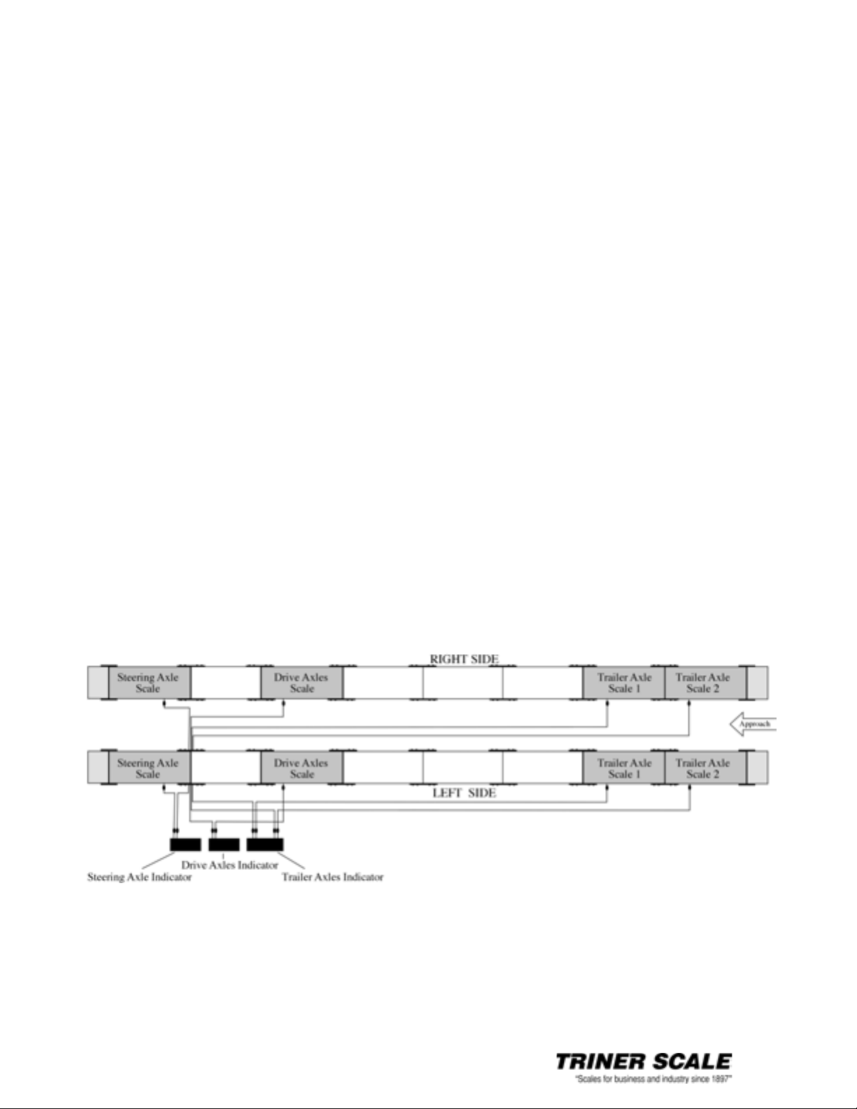
The platforms are labeled in sequence at each junction.
Once in place, the platforms are secured together with brackets. All brackets are labeled
to match up to the platform junctions.
The end ramps are secured to the platforms with a single bolt.
Each scale platform has a cable that runs directly to one of the three digital indicators. All
cables have quick connectors that are plainly labeled.
• The cables from the right side weighing platforms pass through the left side
platforms (at a junction) and then connect to the digital indicators.
• The cables from the left side weighing platforms run directly to the digital
indicators.
• The digital indicators display the weight of the steering axle, the drive axles,
and the trailer axles. The Trailer Axles Indicator displays three weights: Trailer
Axle Scale 1, Trailer Axle Scale 2, and the total weight of both Trailer Axle
Scales.
• The wireless remote displays are factory-interfaced and require no setup
(related digital indicator must be operating).
Page 3

Assembly Guide Axle Weighing Truck Scale
3
Important Note: The location of the scale installation is very important. The scale MUST
be installed on a level concrete surface. Never install the scale on asphalt. Asphalt is not
hard enough to take heavy loads and the scale will sink into the asphalt over time. Ample
space must be available for vehicles to accurately approach and exit the platforms.
1. UNPACK & VERIFY CONTENTS
Below is a list of the parts and quantities:
• Weighing Platforms, Blue (8)
• Ramps, Blue (4)
• Spacer Platforms, Yellow (8)
• Platform Connector Brackets (28)
• Bracket Bolts (112)
• ¾” Anchor Bolts for Platforms (64)
• ½” Anchor Bolts for Digital Indicator Stands (12)
• 100 ft Connecting Cables with Quick-connect Sockets (4)
• 50 ft Connecting Cables with Quick-connect Sockets (4)
• Digital Indicators (3)
• Digital Indicator Stands (3)
• Wireless Scoreboard Remote Displays (3)
2. PLAN YOUR SET UP
Refer to the System Setup Diagram on page 8 for planning your set up.
Determine the track width of the vehicles to be weighed on the scale, as this will
determine the distance required between the left and right platforms.
After the locations of the platforms have been determined, it may be helpful to snap
chalk lines to refer to when fork lifting the platforms into position.
3. FORKLIFT THE PLATFORMS INTO POSITION
Refer to the System Setup Diagram on page 8 when fork lifting the platforms
into position.
Locate the two blue weighing platforms labeled R14 and L14. Per the System Setup
Diagram, place these two platforms at the approach end of the platform arrangement.
Following the System Setup Diagram, continue placing the left and right platforms
into position, matching the end labels in sequence. Be sure to continually check the
platform positions for running in a straight line, and for consistent spacing between
the left side and right side platforms.
4. ATTACH THE PLATFORM BRACKETS
Refer to the System Setup Diagram on page 8 when attaching the platform
brackets.
Place all brackets into positions as marked to match up to the platform junctions
Page 4
Assembly Guide Axle Weighing Truck Scale
4
(when attaching, the brackets can be turned over so that the markings face inward).
Loosely bolt all brackets into position.
Recheck that all platforms are in correct position (a pry bar may be useful for making
small adjustments to the platform positions), and then securely tighten down all
brackets.
5. ATTACH THE FOUR RAMPS
Place the ramps into position and securely bolt down to the end platforms.
6. CHECK PLATFORMS FOR ROCKING
Check all weighing platforms for corner-to-corner rocking. Shim as needed.
7. LOOSEN AND ADJUST THE CHECKING BOLTS ON THE WEIGHING
PLATFORMS
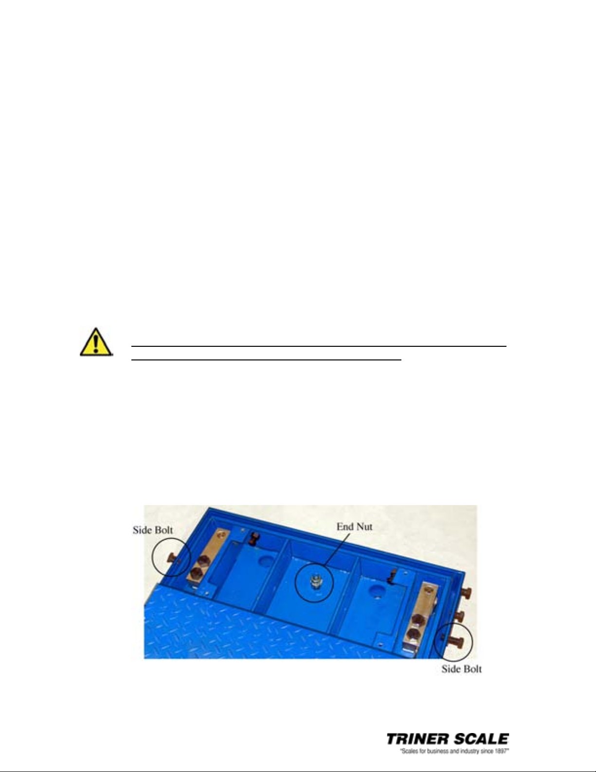
Three checking bolts are located at the end of each weighing platform. These bolts
are tightened down for shipping.
In order for the scales to work properly, all checking bolts on all weighing
platforms must be adjusted after receiving the scale.
Adjust the checking bolts on each platform as follows: Using a #8 allen wrench,
remove all the weighing platform access panels. Referring to the diagram below:
• Back out the two side bolts, and adjust to a 1/2“ gap between the end of
the bolt and the internal frame.
• Back out the end nut, and adjust to 1/2” gap between the nut and the inner
frame floor.
• Replace all access panel covers and securely fasten.
IMPORTANT
Page 5

Assembly Guide Axle Weighing Truck Scale
5
8. ATTACH THE CABLES CONNECTING THE WEIGIHING PLATFORMS
TO THE DIGITAL INDICATORS
Refer to the System Setup Diagram on page 8 when connecting the cables.
Connecting the cables is a simple procedure. The eight cables are equipped with
quick-connect sockets at both ends, enabling easy connection to the weighing
platforms and to the digital indicators.
All weighing platforms have quick-connect sockets on short cables. For protection
during shipping, these connectors are tucked inside the platform. Hang tags are
attached to the cables.
Gently pull out the short quick-connect cable through the cable exit opening on each
weighing platform.
Locate the four 100 ft. cables with connectors labeled 3A, 3B, 3C and 3D.
ATTACH THE CABLES TO THE RIGHT SIDE WEIGHING PLATFORMS
Cables 1B, 2B, 3B and 3D connect to the Right Side Weighing Platforms, and pass
through the Left Side Platforms at junction L1-L2, then run to the digital indicators
located on the left side of the system for viewing by the driver of the truck being
weighed.
• Attach the long cable connector 1B to the matching weighing platform
connector 1B.
• Attach the long cable connector 2B to the matching weighing platform
connector 2B.
• Attach the long cable connector 3B to the matching weighing platform
connector 3B.
• Attach the long cable connector 3D to the matching weighing platform
connector 3D.
• Pass the cables through the Left Side Platforms at junction L1-L2
(between the blue Steering Axle Scale and the yellow spacer platform).
Do not connect to digital indicators at this point.
NOTE: Cables should be run through securely mounted conduit.
The customer determines the conduit installation.
Conduit installation is not covered in this Assembly Guide.
Page 6

Assembly Guide Axle Weighing Truck Scale
6
Locate the four 50 ft. cables with connectors labeled 1A, 2A, 3A and 3C.
ATTACH THE CABLES TO THE LEFT SIDE WEIGHING PLATFORMS
Cables 1A, 2A, 3A and 3C connect to the Left Side Weighing Platforms, and run
directly to the digital indicators.
• Attach the long cable connector 1A to the matching weighing platform
connector 1A.
• Attach the long cable connector 2A to the matching weighing platform
connector 2A.
• Attach the long cable connector 3A to the matching weighing platform
connector 3A.
• Attach the long cable connector 3C to the matching weighing platform
connector 3C.
9. CONNECT WEIGHING PLATFORM CABLES TO THE DIGITAL
INDICATORS
Refer to the System Setup Diagram on page 8 when connecting the cables.
Do not mount the digital indicators on stands at this point.
Indicators mounted on stands that have not been anchored are prone
to severe damage from being knocked over. Place the indicators on a
bench or cart for initial connecting and testing of the system.
Before plugging in the digital indicators to 110VAC, connect all weighing platform
cables to the digital indicators, being sure to match up all of the connector labels, i.e.,
the 1A cable connects to the 1A connector on the Steering Axle digital indicator.
11. POWER ON AND TEST THE SYSTEM
Plug the digital indicators in to 110VAC. Power on the digital indicators by pressing the
red “ON” key and allow the system to warm up several seconds.
Plug in the wireless scoreboard remote displays to 110 VAC.
After a few moments, all displays should read “0” lb. If not, press the “ZERO” key (not
the number 0 key). If displays do not read “0” lb, recheck all connections. Be sure to
power off the indicators before making any changes to the connections. If for any
reason the displays will not read “0” lb, contact Triner Scale technical support toll free
at (800) 238-0152, Mon-Fri 8:00 – 4:30 CST.
With all displays indicating “0” lb, place at least 200 lb of weight on each of the eight
weighing platforms.
• The steering axle scale indicator and wireless remote will display the total
weight placed on platforms 1A and 1B.
• The drive axles scale indicator and wireless remote will display the total weight
placed on platforms 2A and 2B.
IMPORTANT
Page 7

Assembly Guide Axle Weighing Truck Scale
7
• The trailer axles scale indicator will display: the total weight placed on
platforms 3A and 3B, the total weight placed on platforms 3C and 3D, and the
total of all weights placed on platforms 3A through 3D. The wireless remote
will display the total of all weights placed on platforms 3A through 3D.
11. ANCHOR THE SYSTEM AND MOUNT THE DISPLAYS
After rechecking the platforms for corner-to-corner rocking and making any needed
adjustments, anchor the platforms using the provided ¾” anchor bolts. Weighing
platform anchor locations are under the access panels. Spacer platforms have anchor
tabs.
Anchor the digital indicator stands using the provided ½” anchor bolts. Mount the
indicators to the anchored stands.
Mount the wireless scoreboard remote displays as required.
Triner Scale & Mfg. Co., Inc.
8411 Hacks Cross Road
Olive Branch, MS 38654
Tel (662) 890-2385 • Fax (662) 890-2386
Toll Free (800) 238-0152
www.trinerscale.com
Triner Scale Toll Free Technical Support
Mon-Fri 8:00 – 4:30 CST
(800) 238-0152
Page 8

Assembly Guide Axle Weighing Truck Scale
8
Page 9

Assembly Guide Axle Weighing Truck Scale
9
Page 10

Assembly Guide Axle Weighing Truck Scale
10
Triner Scale General Warranty*
What is Covered: Triner Scale warrants to the first end user customer of the Triner
Scale product enclosed with this limited warranty statement that the product, if
purchased and used in the United States, conforms to the manufacturer's
specifications and will be free from defects in workmanship and materials for a period
of one (1) year from the date of original purchase.
What Triner Scale Will Do to Correct Problems: Should your Triner Scale product
prove defective during the warranty period, please call Triner Scale at (800) 238-0152
for warranty repair instructions and return authorization. Triner Scale will, at its option,
repair or replace on an exchange basis the defective unit as follows:
PARTS
New or comparable rebuilt parts in exchange for defective parts for one (1) year after
original purchase.
LABOR
Carry-In or mail in service for 90 days from the date of original purchase. Labor and
shipping cost after the 90 day period will be charged to you.
If you are authorized by Triner Scale to ship the product to Triner Scale for repair, it is
your responsibility to securely package the product in its original container or an
equivalent and provide proof of the date of original purchase. You will be responsible
for shipping costs to Triner Scale repair facility. When warranty service involves the
exchange of the product or a part, the exchanged product may be new or previously
repaired to the Triner Scale standard of quality. Exchange or replacement products or
parts assume the remaining warranty period of the product covered by this limited
warranty.
What this Warranty Does Not Cover: This warranty covers only consumer use in the
United States. Triner Scale is not responsible for warranty service should the Triner
Scale label or logo or the serial number be removed or the product fail to be properly
maintained or fail to function properly as a result of misuse, abuse, improper
installation, neglect, improper shipping, damage caused by disasters such as fire,
flood, and lightning, improper electrical current, interaction with non-Triner Scale
products, or service other than a Triner Scale Authorized Service. Packaging and
shipping costs incurred in presenting your Triner Scale product for warranty service are
your responsibility. If a claimed defect cannot be identified or reproduced in service,
you will be held responsible for costs incurred.
Page 11

Assembly Guide Axle Weighing Truck Scale
11
THE WARRANTY AND REMEDY PROVIDED ABOVE ARE EXCLUSIVE AND IN LIEU OF
ALL OTHER EXPRESS OR IMPLIED WARRANTIES INCLUDING, BUT NOT LIMITED
TO, THE IMPLIED WARRANTIES OF MERCHANTABILITY OR FITNESS FOR A
PARTICULAR PURPOSE. SOME LAWS DO NOT ALLOW THE EXCLUSION OF
IMPLIED WARRANTIES. IF THESE LAWS APPLY, THEN ALL EXPRESS AND IMPLIED
WARRANTIES ARE LIMITED TO THE WARRANTY PERIOD IDENTIFIED ABOVE.
UNLESS STATED HEREIN, ANY STATEMENTS OR REPRESENTATIONS MADE BY
ANY OTHER PERSON OR FIRM ARE VOID. EXPECT AS PROVIDED IN THIS WRITTEN
WARRANTY, NEITHER TRINER SCALE NOR ITS AFFILIATES SHALL BE LIABLE FOR
ANY LOSS, INCONVENIENCE, OR DAMAGE, INCLUDING DIRECT, SPECIAL,
INCIDENTAL OR CONSEQUENTIAL DAMAGES, RESULTING FROM THE USE OR
INABILITY TO USE THE TRINER SCALE PRODUCT, WHETHER RESULTING FROM
BREACH OF WARRANTY OR ANY OTHER LEGAL THEORY.
No terms, condition, underpstanding, or agreements, purporting to modify the terms of
this warranty shall have any legal effect unless made in writing and signed by a
corporate officer of the seller. This warranty gives you specific legal rights, and you my
have other rights which vary from jurisdiction to jurisdiction.
* Warranties may vary on some products purchased through Triner Scale. Contact
Triner Scale directly for confirmation of warranty on your product(s).
 Loading...