

Page 1
USB-2-X
Manual
Version: 2.03
2009-JUN-03
TRINAMIC Motion Control GmbH & Co. KG
D - 20357 Hamburg, Germany
http://www.TRINAMIC.com
Sternstraße 67
Page 2

USB-2-X Manual (V2.03/2009-JUN-03) 2
Table of Contents
1 Life support policy ................................................................................................................................................................... 3
2 Features ....................................................................................................................................................................................... 4
3 Order codes ................................................................................................................................................................................ 6
4 Mechanical and electrical interfacing ................................................................................................................................. 7
4.1 Dimensions of the USB-2-X ........................................................................................................................................... 7
4.2 Connectors ......................................................................................................................................................................... 8
4.2.1 CAN connector ......................................................................................................................................................... 9
4.2.2 LIN, IIC, and SPI connectors ............................................................................................................................... 9
4.2.3 RS485 connector ...................................................................................................................................................... 9
5 Putting the USB-2-X into operation................................................................................................................................... 10
5.1 Starting up ....................................................................................................................................................................... 10
5.2 Software ........................................................................................................................................................................... 10
5.2.1 The USB-2-X with a TMC211 evaluation board ............................................................................................. 10
5.2.2 The USB-2-X with a TMC222 evaluation board ............................................................................................. 10
5.2.3 The USB-2-X.EXE software for any other application .................................................................................. 10
5.2.4 Further information about the software ....................................................................................................... 11
6 Updating the firmware ......................................................................................................................................................... 12
7 Revision history ...................................................................................................................................................................... 13
7.1 Document revision ........................................................................................................................................................ 13
7.2 Firmware revision .......................................................................................................................................................... 13
8 References................................................................................................................................................................................. 14
Table of tables
Table 2.1: Interfaces of the USB-2-X ............................................................................................................................................ 5
Table 3.1: Order codes ..................................................................................................................................................................... 6
Table 4.1: CAN connector ................................................................................................................................................................ 9
Table 4.2: LIN, IIC, and SPI connectors ...................................................................................................................................... 9
Table 4.3: RS485 connector............................................................................................................................................................. 9
Table 7.1: Document revision ...................................................................................................................................................... 13
Table 7.2: Firmware revision ........................................................................................................................................................ 13
Table of figures
Figure 2.1: Block diagram of the USB-2-X .................................................................................................................................. 4
Figure 4.1: Dimensions of the USB-2-X ....................................................................................................................................... 7
Figure 4.2: The USB-2-X device ...................................................................................................................................................... 8
Figure 4.3: The PCB of the USB-2-X device ................................................................................................................................ 8
Copyright © 2009, TRINAMIC Motion Control GmbH & Co. KG
Page 3

USB-2-X Manual (V2.03/2009-JUN-03) 3
1 Life support policy
TRINAMIC Motion Control GmbH & Co. KG does not
authorize or warrant any of its products for use in life
support systems, without the specific written consent of
TRINAMIC Motion Control GmbH & Co. KG.
Life support systems are equipment intended to support or
sustain life, and whose failure to perform, when properly
used in accordance with instructions provided, can be
reasonably expected to result in personal injury or death.
© TRINAMIC Motion Control GmbH & Co. KG 2005
Information given in this data sheet is believed to be
accurate and reliable. However neither responsibility is
assumed for the consequences of its use nor for any
infringement of patents or other rights of third parties,
which may result from its use.
Specifications are subject to change without notice.
Copyright © 2009, TRINAMIC Motion Control GmbH & Co. KG
Page 4
USB-2-X Manual (V2.03/2009-JUN-03) 4
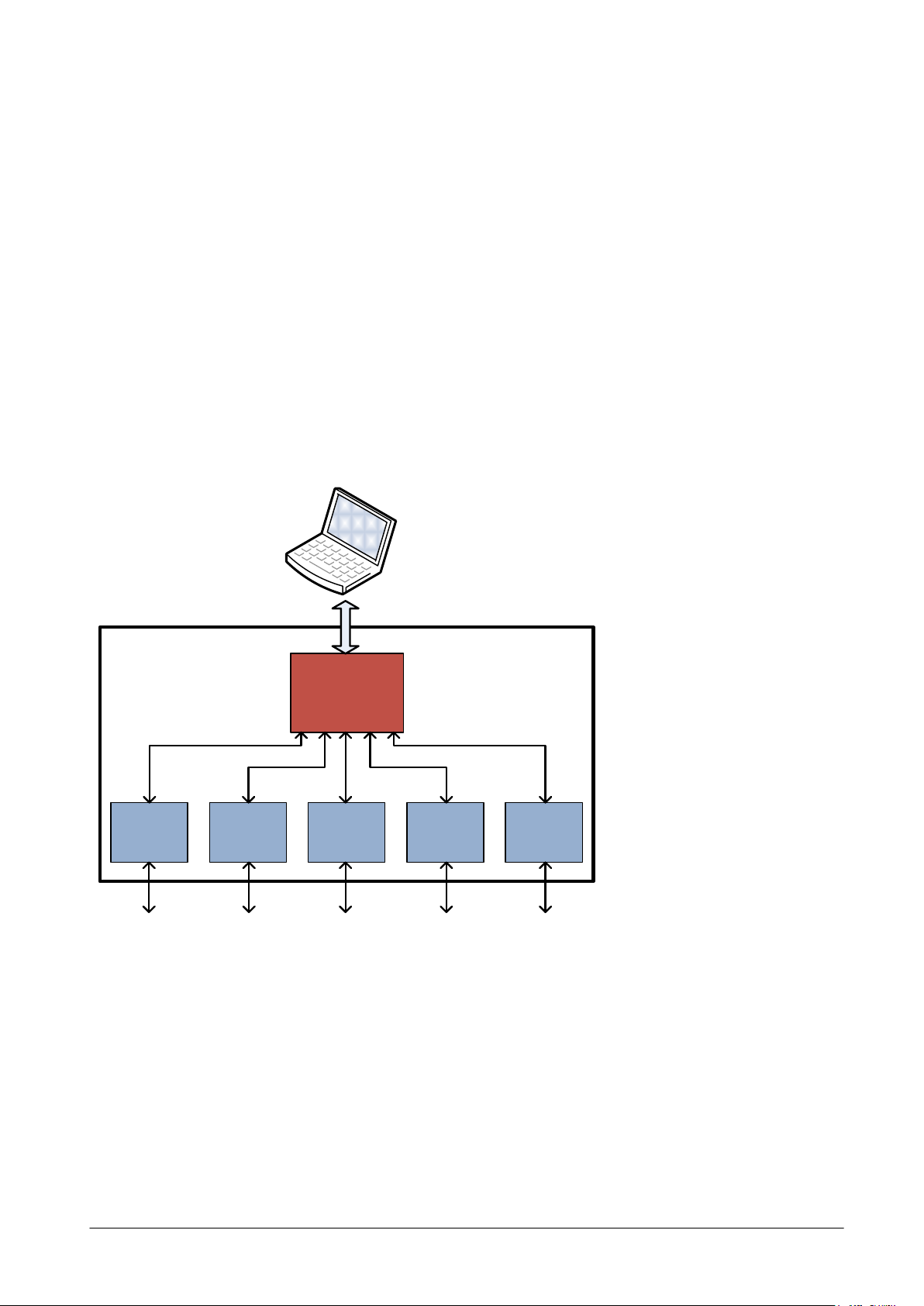
USB
CAN IIC LIN SPI RS485
USB-2-X
2 Features
The USB-2-X device is an interface converter which is equipped with a CAN interface, an IIC interface, a LIN
interface, an SPI interface and an RS485 interface. It can be connected to the PC via the USB interface.
The USB-2-X device is mainly designed for use with some of the TRINAMIC evaluation kits, but it can also be
used in any other purpose where a connection between a PC and a CAN interface, an IIC interface, a LIN
interface, an SPI interface or an RS485 interface is needed.
Its frame is a compact, metalized standard housing (known as 25 pin Sub-D adapter housing) with the
dimensions 53mm x 55mm x 16mm (length x width x height). Please notice that plugs and cables need
further space.
The software supplied with this product can be used with every version of the Windows operating system
that supports USB (Windows 98, Windows ME, Windows 2000, Windows XP and Windows Vista). Windows
95 and Windows NT4.0 do not support USB, so the USB-2-X device cannot be used with such systems.
Figure 2.1: Block diagram of the USB-2-X
Copyright © 2009, TRINAMIC Motion Control GmbH & Co. KG
Page 5

USB-2-X Manual (V2.03/2009-JUN-03) 5
Interface
Description
USB
- Connection to USB 1.1 or USB 2.0 hosts (cable supplied with the device)
- USB full speed device (12MBit/s)
- Bus powered (no extra power supply needed)
CAN
- CAN 2.0A and 2.0B compatible
- Standard (11 bit) and extended (29 bit) identifier possible
- Transceiver: compatible with ISO 11898 standard
- Maximum bit rate: 1MBit/s
- 120 ohms termination resistor can be activated with a jumper
LIN
- Compatible with LIN specification rev 1.3
- up to 20kBit/s
- Industry standard physical interface transceiver
IIC
- Single master
- Up to 400kBit/s
- 7-bit addressing
- Supports clock stretching (wait condition initiated by master)
SPI
- Four standard signals: SCK, MOSI, MISO, SS (slave select)
- Additional 5
th
line SR: slave request signal input (falling edge active, internal pull-
up)
- Software selectable signal levels: 5V or 3.3V
- Master mode operation
- Silent slave mode (spy mode) possible when MISO is not connected to the target
- Clock phase and polarity: all four modes software selectable
- Setup and hold time of slave select signal as well as inter-byte delay time
software selectable
- Data rates: up to 3.75 MBit/s at 5V, up to 1.5 MBit/s at 3.3V
RS485
- Half duplex communication mode
- Industry standard 75176 transceiver
- 2400, 9600 and 19200 bps supported
- Pull-up resistor, pull-down resistor and termination resistor possible (assembly
option on request)
The following table shows all available interfaces of the USB-2-X with its characteristics:
Table 2.1: Interfaces of the USB-2-X
Copyright © 2009, TRINAMIC Motion Control GmbH & Co. KG
Page 6

USB-2-X Manual (V2.03/2009-JUN-03) 6
Order code
Description
Length of unit
USB-2-X V2.0
USB interface converter (with USB cable)
62.2 x 54.4 x 16.9 mm
3 Order codes
Table 3.1: Order codes
Copyright © 2009, TRINAMIC Motion Control GmbH & Co. KG
Page 7
USB-2-X Manual (V2.03/2009-JUN-03) 7
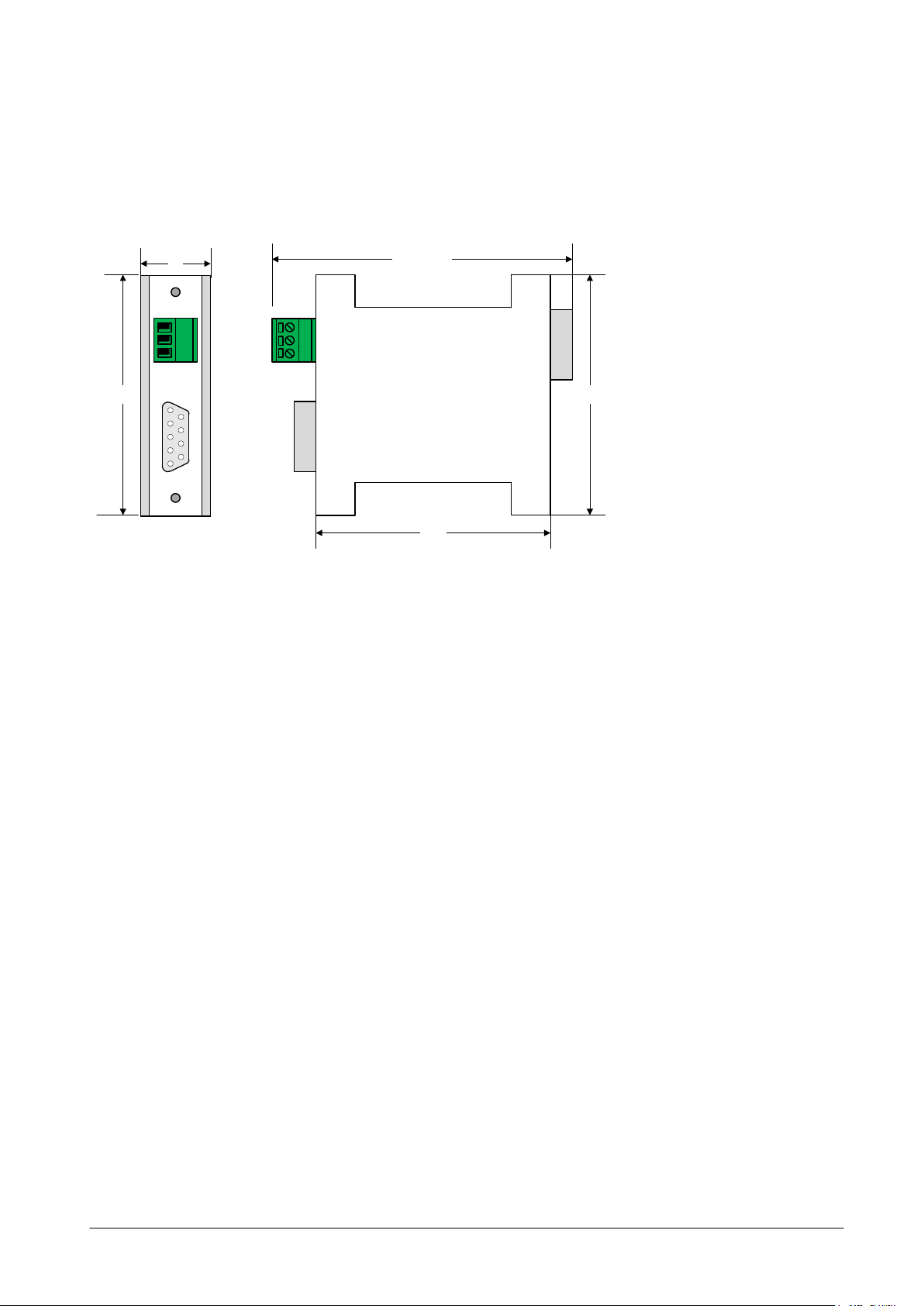
53.5
55
68.5 max
USB-2-X
55
16
4 Mechanical and electrical interfacing
4.1 Dimensions of the USB-2-X
Figure 4.1: Dimensions of the USB-2-X
Copyright © 2009, TRINAMIC Motion Control GmbH & Co. KG
Page 8

USB-2-X Manual (V2.03/2009-JUN-03) 8
CAN connector
USB connector
USB-2-X
RS 485 connector
GND
B
A
IIC / LIN / SPI
connector
4.2 Connectors
First a little overview: Figure 5.1 shows where which interface is located and Figure 5.2 shows the PCB of
the USB-2-X interface.
Figure 4.2: The USB-2-X device
Copyright © 2009, TRINAMIC Motion Control GmbH & Co. KG
Figure 4.3: The PCB of the USB-2-X device
Page 9
USB-2-X Manual (V2.03/2009-JUN-03) 9
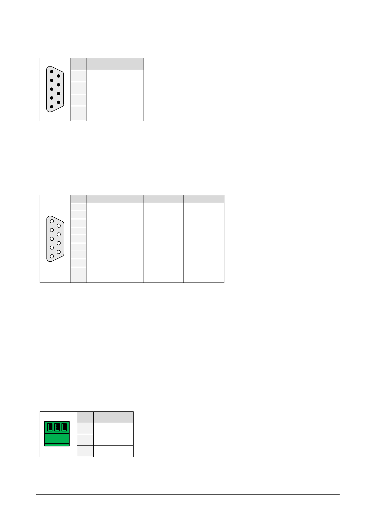
1
6
9
5
Pin
Signal
2
CAN_LOW
7
CAN_HI
3
GND
6
GND
5
9
6
1
Pin
Signal (LIN)
Signal (IIC)
Signal (SPI)
1 SCL 2
SCK
3
GND
GND
GND
4
SS 5 MOSI
6 SDA
7
LIN (data)
8
MISO
9
LIN supply voltage
(+8..18VDC)
1 2 3
Pin
Signal
1
A (+)
2
B (-)
3
GND
4.2.1 CAN connector
Table 4.1: CAN connector
A CAN termination resistor of 120 ohms can be activated shorting the two pin header placed below
the USB connector using a jumper.
4.2.2 LIN, IIC, and SPI connectors
Table 4.2: LIN, IIC, and SPI connectors
When LIN is used, the LIN transceiver of the USB-2-X device has to be powered by the target via pin
9 of the connector.
The pin assignment has been selected in order to allow direct connection to the TRINAMIC TMC211
evaluation board and the TRINAMIC TMC222 evaluation board.
Please note that the additional SR (slave request) line of the SPI interface is not available on this
connector but on a board edge solder pad (the second of eight solder pads counted starting from IC
labeled 75176).
The IIC interface and the SPI interface cannot be used simultaneously.
Also, the LIN interface and the RS485 interface cannot be used simultaneously.
4.2.3 RS485 connector
Table 4.3: RS485 connector
Copyright © 2009, TRINAMIC Motion Control GmbH & Co. KG
Page 10

USB-2-X Manual (V2.03/2009-JUN-03) 10
5 Putting the USB-2-X into operation
5.1 Starting up
1) As USB devices are hot pluggable it is not necessary to turn off the PC when plugging in or
removing the USB-2-X device. Just plug in the device when the PC is switched on and Windows is
running.
2) When you plug in the USB-2-X device for the first time you will be prompted for a suitable device
driver after a few seconds. You will have to be logged in as administrator to be able to install
device drivers on Windows 2000 or Windows XP.
3) Insert the TMC TechLib CD that is supplied with this product and select the USB2X.INF file in the
interfaces\USB2X directory on the TechLib CD.
4) The device driver will be installed. Now the USB-2-X device can be used.
5.2 Software
5.2.1 The USB-2-X with a TMC211 evaluation board
If you are using the USB-2-X device with a TMC211 evaluation board, use the software that is supplied with
the evaluation board: Eval211USB.exe. This software is described in the manual of the TMC211 evaluation
board.
5.2.2 The USB-2-X with a TMC222 evaluation board
If you are using the USB-2-X device with a TMC222 evaluation board, use the software that is supplied with
the TMC222 evaluation board: Eval222USB.exe. It is described in the manual that comes with the TMC222
evaluation board.
5.2.3 The USB-2-X.EXE software for any other application
With this software you can send and receive any data using the interfaces of the USB-2-X device.
Start up as follows:
1) Start the program by double clicking the file USB2X.EXE which is supplied in the interfaces\USB2X
directory of the TechLib CD.
2) The main window appears. Select your USB-2-X device in the interface section.
3) Click the Open button.
4) After the connection to the device has been successfully established, the firmware revision number
of the device is shown.
Copyright © 2009, TRINAMIC Motion Control GmbH & Co. KG
Page 11

USB-2-X Manual (V2.03/2009-JUN-03) 11
5.2.4 Further information about the software
On the IIC, LIN, CAN, SPI and RS485 tab pages you can find all functions to make use of the interfaces of
the USB-2-X device. Please check TRINAMIC’s web site from time to time and watch out for updates (of the
PC software and the firmware).
Notes on using the USB-2-X device in your own PC software can be found in the documentation of the USB2-X host interface protocol. There is also an example program, written in Delphi.
In the near future there will also be a DLL that will make integrating the USB-2-X device into your own
devices very easy. Please check TRINAMIC’s web site from time to time if it is already available.
Additional support tools for the USB-2-X are also available. Please check our website www.TRINAMIC.com to
find the temperature logger to measure 8 temperatures via IIC with a LM75 chip or a chip programmer to
read out and write via SPI, IIC or micro wire to EEPROMS and SPI chips like the TMC428.
Copyright © 2009, TRINAMIC Motion Control GmbH & Co. KG
Page 12

USB-2-X Manual (V2.03/2009-JUN-03) 12
6 Updating the firmware
The USB2X.EXE software also makes it possible to update the firmware of the USB-2-X device via its USB
interface. Firmware files for the USB-2-X device can be downloaded on TRINAMIC’s website
(www.TRINAMIC.com).
For installing a new firmware file, please follow the instructions:
1) Download the file from TRINAMIC’s web site. Firmware files for the USB-2-X device normally have
the extension .s19.
2) Start the USB-2-X PC software and click the Open button.
3) Click the Firmware update button. A new window appears.
4) Click the Load button and select your new firmware file.
5) Click the Start button and wait for the update process to complete.
6) Try if the USB-2-X device still works.
If this should not be the case, quit the USB-2-X software, pull out the USB plug on the USB-2-X
device, wait some seconds and plug it in again. Now restart the USB-2-X software and try again.
If for some reason the USB-2-X device should still refuse to work, try to update the firmware again.
Copyright © 2009, TRINAMIC Motion Control GmbH & Co. KG
Page 13

USB-2-X Manual (V2.03/2009-JUN-03) 13
Version
Comment
Author
Description
1.00
2004-NOV-27
OK
Initial version
1.01
2004-OKT-01
OK
Minor error corrections
2.00
2005-JAN-24
OK
Describes USB-2-X Version 2
2.01
2005-NOV-23
OK
CAN connector pin assignments corrected
2.02
2007-SEP-19
HC
Clock stretching info for IIC, RS485 pin assignment in Fehler!
Verweisquelle konnte nicht gefunden werden. corrected
2.03
2009-JUN-03
SD
Life support policy, order codes, and block diagram added.
Minor changes.
Version
Comment
Description
V2.10
2007-JUL-19
Supports clock stretching for IIC
7 Revision history
7.1 Document revision
Table 7.1: Document revision
7.2 Firmware revision
Table 7.2: Firmware revision
Copyright © 2009, TRINAMIC Motion Control GmbH & Co. KG
Page 14

USB-2-X Manual (V2.03/2009-JUN-03) 14
8 References
[USB-2-X] USB interface converter (see http://www.trinamic.com)
Copyright © 2009, TRINAMIC Motion Control GmbH & Co. KG
 Loading...