

1-Axis BLDC
Controller / Driver Module
5A / 24 V
Hall Sensor Interface
Encoder Interface
RS485 and USB Interface
FOC Firmware
MODULE FOR BLDC MOTORS MODULE
Firmware Version V2.00
TMCL™ FIRMWARE MANUAL
+ +
+ +
TMCM-1640
TRINAMIC Motion Control GmbH & Co. KG
Hamburg, Germany
www.trinamic.com

TMCM-1640 TMCL Firmware V2.00 Manual (Rev. 2.00 / 2012-JUL-31) 2
Table of Contents
1 Features ........................................................................................................................................................................... 4
2 Overview ......................................................................................................................................................................... 5
3 Putting the TMCM-1640 into Operation .................................................................................................................. 6
3.1 Starting up ............................................................................................................................................................. 6
3.2 Operating the Module in Direct Mode ........................................................................................................... 9
4 TMCL™ ........................................................................................................................................................................... 10
4.1 Binary Command Format ................................................................................................................................ 10
4.2 Reply Format ....................................................................................................................................................... 11
4.2.1 Status Codes ................................................................................................................................................. 11
4.3 Standalone Applications .................................................................................................................................. 12
4.4 Testing with a Simple TMCL Program ......................................................................................................... 12
4.5 TMCL Command Overview .............................................................................................................................. 13
4.5.1 Motion Commands ...................................................................................................................................... 13
4.5.2 Parameter Commands ................................................................................................................................ 13
4.5.3 Control Commands ..................................................................................................................................... 13
4.5.4 I/O Port Commands .................................................................................................................................... 13
4.5.5 Calculation Commands .............................................................................................................................. 14
4.6 Commands ........................................................................................................................................................... 15
4.6.1 ROR (rotate right)......................................................................................................................................... 15
4.6.2 ROL (rotate left) ............................................................................................................................................ 16
4.6.3 MST (motor stop) ......................................................................................................................................... 17
4.6.4 MVP (move to position) ............................................................................................................................. 18
4.6.5 SAP (set axis parameter) ........................................................................................................................... 19
4.6.6 GAP (get axis parameter) ........................................................................................................................... 20
4.6.7 STAP (store axis parameter) ..................................................................................................................... 21
4.6.8 RSAP (restore axis parameter) ................................................................................................................. 22
4.6.9 SGP (set global parameter) ....................................................................................................................... 23
4.6.10 GGP (get global parameter) ...................................................................................................................... 24
4.6.11 STGP (store global parameter) ................................................................................................................. 24
4.6.12 RSGP (restore global parameter) ............................................................................................................. 25
4.6.13 SIO (set output) and GIO (get input / output) ................................................................................... 26
4.6.14 CALC (calculate) ............................................................................................................................................ 28
4.6.15 COMP (compare) ........................................................................................................................................... 29
4.6.16 JC (jump conditional).................................................................................................................................. 30
4.6.17 JA (jump always).......................................................................................................................................... 31
4.6.18 CSUB (call subroutine) and RSUB (return from subroutine) ........................................................... 32
4.6.19 WAIT (wait for an event to occur) ......................................................................................................... 33
4.6.20 STOP (stop TMCL program execution) ................................................................................................... 34
4.6.21 CALCX (calculate using the X register) .................................................................................................. 35
4.6.22 AAP (accumulator to axis parameter) .................................................................................................... 36
4.6.23 AGP (accumulator to global parameter) ............................................................................................... 37
4.6.24 Customer Specific TMCL Command Extension (user functions 0… 7) ........................................... 37
4.6.25 Command 136 - Get Firmware Version ................................................................................................. 38
5 Axis Parameter Overview (SAP, GAP, STAP, RSAP, AAP) ................................................................................. 39
5.1 Axis Parameter Sorted by Functionality ...................................................................................................... 43
6 Global Parameter Overview (SGP, GGP, STGP, RSGP) ....................................................................................... 47
6.1 Bank 0 ................................................................................................................................................................... 47
6.2 Bank 2 ................................................................................................................................................................... 48
7 Motor Regulation ........................................................................................................................................................ 49
7.1 Structure of the Cascaded Motor Regulation Modes............................................................................... 49
7.2 Current Regulation ............................................................................................................................................ 50
7.3 Velocity Regulation ........................................................................................................................................... 51
7.4 Velocity Ramp Generator ................................................................................................................................. 52
7.5 Position Regulation ........................................................................................................................................... 52
8 Temperature Calculation........................................................................................................................................... 54
9 I²t Monitoring .............................................................................................................................................................. 54
10 Life Support Policy ..................................................................................................................................................... 55
www.trinamic.com

TMCM-1640 TMCL Firmware V2.00 Manual (Rev. 2.00 / 2012-JUL-31) 3
11 Revision History .......................................................................................................................................................... 56
11.1 Firmware Revision ............................................................................................................................................. 56
11.2 Document Revision ........................................................................................................................................... 56
12 References..................................................................................................................................................................... 56
www.trinamic.com

TMCM-1640 TMCL Firmware V2.00 Manual (Rev. 2.00 / 2012-JUL-31) 4
1 Features
The TMCM-1640 is a highly compact controller/driver module for brushless DC (BLDC) motors with up to 5A
coil current, optional encoder and/or hall sensor feedback. For communication the module offers RS485 and
(mini-)USB interface.
Applications
- Compact single-axis brushless DC motor solutions
Electrical data
- Supply voltage: +24V DC nom. (+12V… +28.5V DC)
- Motor current: up to 5A RMS (programmable)
Integrated motion controller
- High performance microcontroller for system control and communication protocol handling
Integrated driver
- High performance integrated pre-driver (TMC603)
- High-efficient operation, low power dissipation (MOSFETs with low R
- Dynamic current control
- Integrated protection
Interfaces
- USB (mini-USB, full speed (12Mbit/s)) serial communication interface
- RS485 serial communication interface
- Hall sensor interface (+5V TTL or open-collector signals)
- Encoder interface (+5V TTL or open-collector signals)
- General purpose inputs (2x digital (+5V / +24V compatible), 1x analogue (+0… +10V)
- 1 general purpose output (open-drain)
Software
- Available with TMCL
- Standalone operation or remote controlled operation
- Program memory (non volatile) for up to 2048 TMCL commands
- PC-based application development software TMCL-IDE
- PC-based control software TMCM-BLDC for initial adjustments
Refer to separate TMCM-1640 Hardware Manual, too.
DS(ON)
)
www.trinamic.com

TMCM-1640 TMCL Firmware V2.00 Manual (Rev. 2.00 / 2012-JUL-31) 5
2 Overview
The software running on the microprocessor of the TMCM-1640 consists of two parts, a boot loader and the
firmware itself. Whereas the boot loader is installed during production and testing at TRINAMIC and remains
– normally – untouched throughout the whole lifetime, the firmware can be updated by the user. New
versions can be downloaded free of charge from the TRINAMIC website (http://www.trinamic.com).
The firmware is related to the standard TMCL firmware with regard to protocol and commands. The module
is based on the ARM Cortex-M3 microcontroller and the high performance pre-driver TMC603 and supports
the standard TMCL with a special range of values.
The new FOC firmware V2.0 is field oriented control software for brushless DC applications. It is developed
for high-performance motor applications which can operate smoothly over the full velocity range, can
generate full torque at zero speed and is capable of fast acceleration and deceleration. This saves energy
and quiets rotating machinery.
www.trinamic.com
TMCM-1640 TMCL Firmware V2.00 Manual (Rev. 2.00 / 2012-JUL-31) 6
Motor
USB
Power
GPIO
1
1
1
1
1
Hall
Encoder
Domain
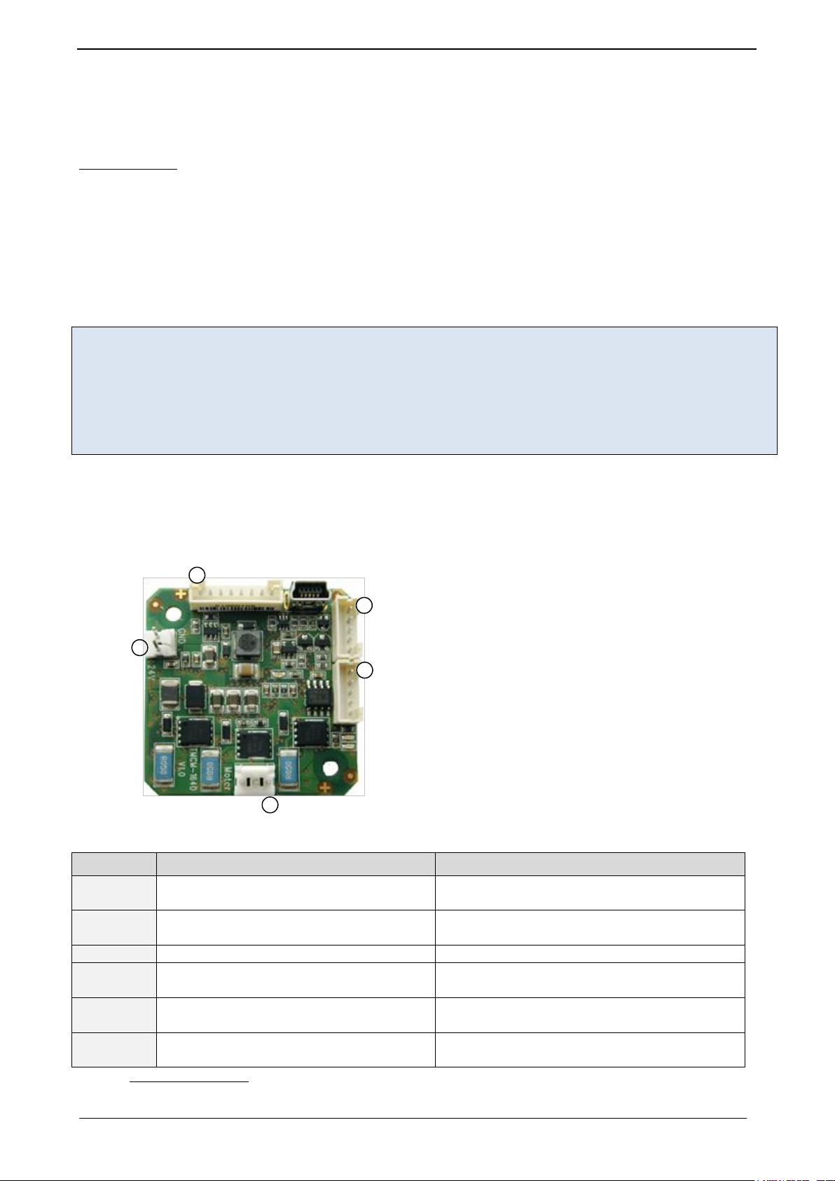
Connector type
Mating connector type
Power
Tyco electronics (formerly AMP) MTA-100
series (3-640456-2), 2 pol., male
MTA 100 series (3-640441-2), 2 pol., female
Motor
Tyco electronics (formerly AMP) MTA-100
series (3-640456-3), 3 pol., male
MTA 100 series (3-640441-3), 3 pol., female
USB
5-pin standard mini-USB connector, female
5-pin standard mini-USB connector, male
Hall
2mm pitch 5 pin JST B5B-PH-K connector
Housing: JST PHR-5
Crimp contacts: BPH-002T-P0.5S (0.5-0.22mm)
Encoder
2mm pitch 5 pin JST B5B-PH-K connector
Housing: JST PHR-5
Crimp contacts: BPH-002T-P0.5S (0.5-0.22mm)
I/O, RS485
2mm pitch 8 pin JST B8B-PH-K connector
Housing: JST PHR-8
Crimp contacts: BPH-002T-P0.5S (0.5-0.22mm)
3 Putting the TMCM-1640 into Operation
Here you can find basic information for putting your module into operation. The text contains a simple
example for a TMCL program and a short description of operating the module in direct mode.
THINGS YOU NEED:
- TMCM-1640
- USB interface and appropriate cable or RS485 interface / adapter and appropriate cable
- Nominal supply voltage +24V DC (+12… +28.5V DC) for your module with sufficient output filtering
(to be sure add e.g. 2200µF capacitor close to power supply input of module)
- BLDC motor, e.g. one of TRINAMICs QBL4208 motors
- Encoder optional
- TMCL-IDE program and PC
PRECAUTIONS
- Do not mix up connections or short-circuit pins.
- Avoid bounding I/O wires with motor power wires as this may cause noise picked up from the motor supply.
- The power supply has to be buffered by a capacitor. Otherwise the module will be damaged!
- Do not exceed the maximum power supply of 28.5V DC.
- Do not connect or disconnect the motor while powered!
- Start with power supply OFF!
3.1 Starting up
The following figure shows how the connectors have to be used.
1. Connect the motor:
www.trinamic.com

TMCM-1640 TMCL Firmware V2.00 Manual (Rev. 2.00 / 2012-JUL-31) 7
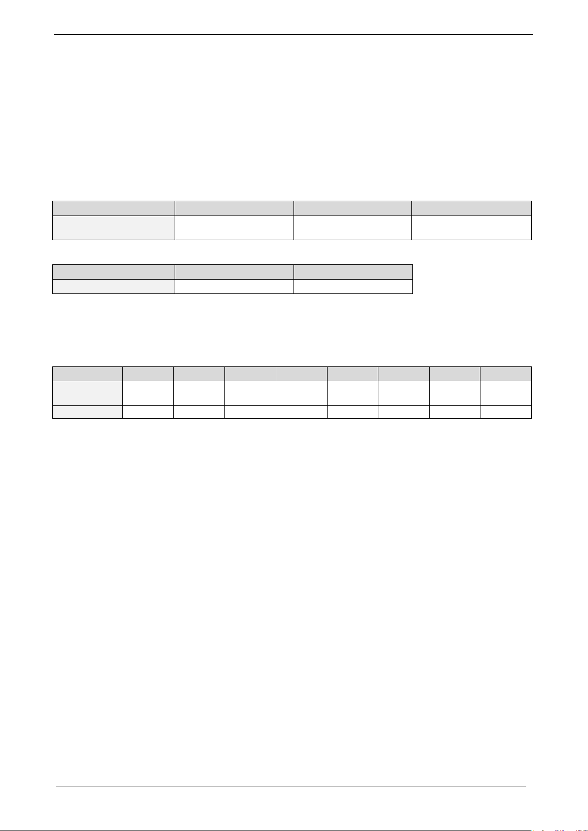
Pin
Label
Description
1
BM1
Motor coil phase 1 / U
2
BM2
Motor coil phase 2 / V
3
BM3
Motor coil phase 3 / W
Pin
Label
Description
1
GND
Encoder supply and signal ground
2
+5V
+5V output for encoder supply (max. 100mA)
3 A Encoder channel a
4 B Encoder channel b
5 N Encoder index / null channel
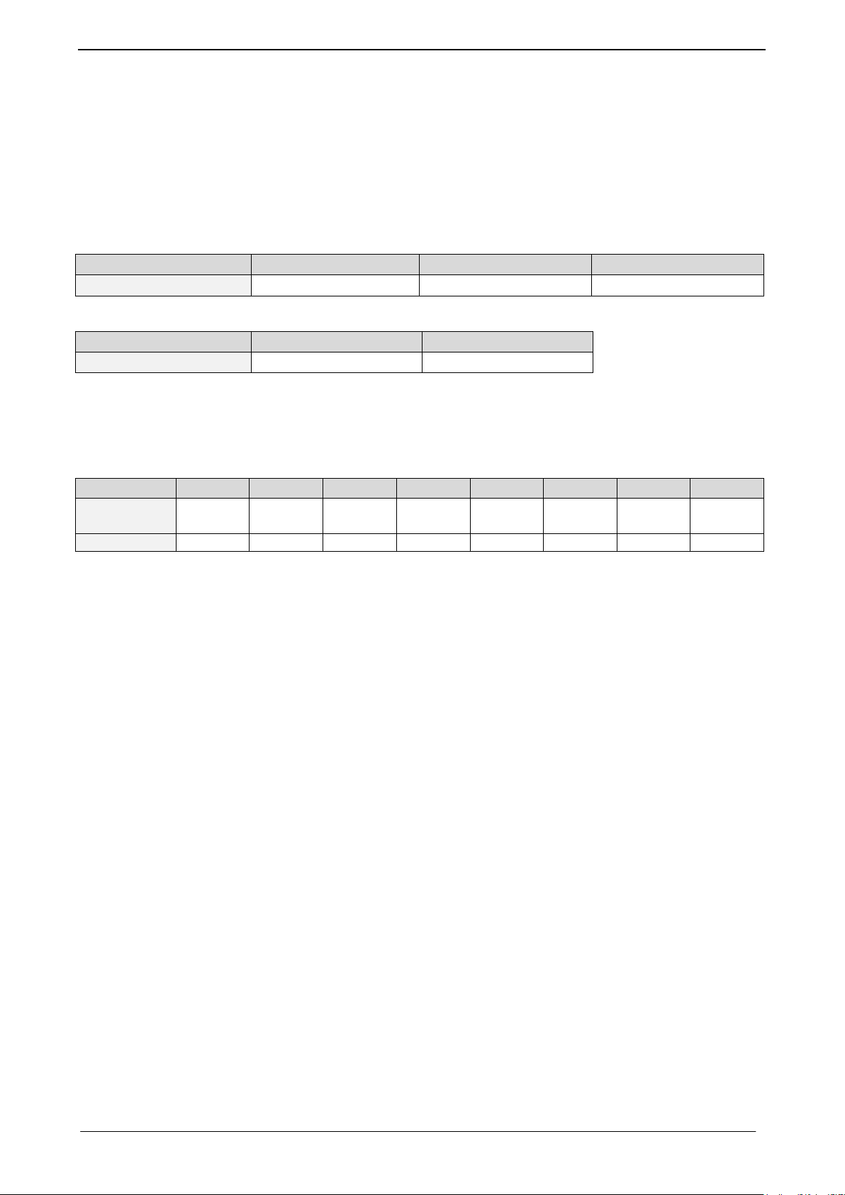
Pin
Label
Description
1
GND
Encoder supply and signal ground
2
+5V
+5V output for hall sensor supply
3
HALL_1
Hall sensor signal 1
4
HALL_2
Hall sensor signal 2
5
HALL_3
Hall sensor signal 3
Pin
Label
Description
1
GND
Signal and system ground
2
+5V
+5V output for supply of external circuit
(max. 100mA)
3
AIN
Analog input (0..10V), may be used as
velocity control input in standalone mode
(depending on initial script)
4
IN_0
Digital input, may be used as stop (STOP_R)
/ limit switch input (if activated)
5
IN_1
Digital input, may be used as stop (STOP_L) /
limit switch input (if activated)
6
OUT
Digital output (open-drain, max. 100mA)
7
RS485+
RS485 2-wire serial interface (non-inverted
signal)
8
RS485-
RS485 2-wire serial interface (inverted signal)
Pin
Label
Description
1
VBUS
+5V power
2
D-
Data –
3
D+
Data +
4
ID
Not connected
5
GND
Ground
2. Connect the encoder (optional):
3. Connect the hall sensor:
4. Connect the I/Os and the RS485 interface, if needed:
5. Connect the USB interface:
www.trinamic.com

TMCM-1640 TMCL Firmware V2.00 Manual (Rev. 2.00 / 2012-JUL-31) 8
Pin
Label
Description
1
+U
Module and driver stage power supply input
2
GND
Module ground (power supply and signal
ground)
GUIDELINES FOR POWER SUPPLY:
a) keep power supply cables as short as possible
b) use cables with large diameters for power supply cables
c) add 2200µF or larger filter capacitors near the motor driver unit especially if the distance to
the power supply is large (i.e. more than 2-3m)
6. Connect the power supply as follows:
Please note, that there is no protection against reverse polarity and only limited protection
against voltages above the upper maximum limit. The power supply typically should be within
a range of +12 to +28.5V.
When using supply voltages near the upper limit, a regulated power supply is mandatory. Please
ensure that enough power filtering capacitors are available in the system (2200µF or more
recommended) in order to absorb energy fed back by the motor while the motor is decelerating and
in order to prevent any voltage surge e.g. during power-on (especially with longer power supply
cables as there are only ceramic filter capacitors on-board). In larger systems an additional external
zener/suppressor diode with adequate voltage rating might be necessary in order to limit the
maximum voltage.
To ensure reliable operation of the unit, the power supply has to have a sufficient output capacitor
and the supply cables should have a low resistance, so that the chopper operation does not lead to
an increased power supply ripple directly at the unit. Power supply ripple due to the chopper
operation should be kept at a maximum of a few 100mV
7. Switch ON the power supply
The power LED glows now. If this does not occur, switch power OFF and check your connections as
well as the power supply.
8. Start the TMCL-IDE software development environment
The TMCL-IDE is available on www.trinamic.com.
Installing the TMCL-IDE
Make sure the COM port you intend to use is not blocked by another program.
Open TMCL-IDE by clicking TMCL.exe.
PROCEED AS FOLLOWS:
Choose Setup and Options as shown in Figure 3.1.
Choose the Connection tab.
Choose Type.
The TMCL-IDE shows you which Port the module uses.
Click OK.
www.trinamic.com

TMCM-1640 TMCL Firmware V2.00 Manual (Rev. 2.00 / 2012-JUL-31) 9
Direct Mode
Figure 3.1: Setup menu Figure 3.2: Connection tab of TMCL-IDE
3.2 Operating the Module in Direct Mode
Start TMCL Direct Mode.
If the communication is established the TMCM-1640 is automatically detected. If the module is not detected,
please check all points above (cables, interface, power supply, COM port, baud rate).
Issue a command by choosing Instruction, Type (if necessary), Motor, and Value and click Execute to send
it to the module.
Examples:
ROR rotate right, motor 0, value 500 -> Click Execute. The first motor is rotating now.
MST motor stop, motor 0 -> Click Execute. The first motor stops now.
www.trinamic.com

TMCM-1640 TMCL Firmware V2.00 Manual (Rev. 2.00 / 2012-JUL-31) 10
Bytes
Meaning
1
Module address
1
Command number
1
Type number
1
Motor or Bank number
4
Value (MSB first!)
1
Checksum
4 TMCL™
The TMCM-1640 module supports TMCL direct mode and standalone TMCL program execution. You can store
up to 2048 TMCL instructions on it.
In direct mode the TMCL communication over USB/RS485 follows a strict master/slave relationship. That is, a
host computer (e.g. PC/PLC) acting as the interface bus master will send a command to the module. The
TMCL interpreter on it will then interpret this command, do the initialization of the motion controller, read
inputs and write outputs or whatever is necessary according to the specified command. As soon as this step
has been done, the module will send a reply back over USB/RS485 to the bus master. The master should not
transfer the next command till then. Normally, the module will just switch to transmission and occupy the
bus for a reply, otherwise it will stay in receive mode. It will not send any data over the interface without
receiving a command first. This way, any collision on the bus will be avoided when there are more than
two nodes connected to a single bus.
The Trinamic Motion Control Language (TMCL) provides a set of structured motion control commands. Every
motion control command can be given by a host computer or can be stored on the TMCM-1640 to form
programs that run standalone on the module.
Every command has a binary representation and a mnemonic:
- The binary format is used to send commands from the host to a module in direct mode.
- The mnemonic format is used for easy usage of the commands when developing standalone TMCL
applications with the TMCL-IDE (IDE means Integrated Development Environment).
There is also a set of configuration variables for the axis and for global parameters which allow individual
configuration of nearly every function of a module. This manual gives a detailed description of all TMCL
commands and their usage.
4.1 Binary Command Format
When commands are sent from a host to a module, the binary format has to be used. Every command
consists of a one-byte command field, a one-byte type field, a one-byte motor/bank field and a four-byte
value field. So the binary representation of a command always has seven bytes.
When a command is to be sent via USB interface, it has to be enclosed by an address byte at the beginning
and a checksum byte at the end. In this case it consists of nine bytes.
The binary command format for USB and RS485 is structured as follows:
www.trinamic.com

TMCM-1640 TMCL Firmware V2.00 Manual (Rev. 2.00 / 2012-JUL-31) 11
Bytes
Meaning
1
Reply address
1
Module address
1
Status (e.g. 100 means no error)
1
Command number
4
Value (MSB first!)
1
Checksum
Code
Meaning
100
Successfully executed, no error
101
Command loaded into TMCL
program EEPROM
1
Wrong checksum
2
Invalid command
3
Wrong type
4
Invalid value
5
Configuration EEPROM locked
6
Command not available
Checksum calculation
As mentioned above, the checksum is calculated by adding up all bytes (including the module address byte)
using 8-bit addition. Here is an example for the calculation:
in C:
unsigned char i, Checksum;
unsigned char Command[9];
//Set the “Command” array to the desired command
Checksum = Command[0];
for(i=1; i<8; i++)
Checksum+=Command[i];
Command[8]=Checksum; //insert checksum as last byte of the command
//Now, send the command back to the module
4.2 Reply Format
Every time a command has been sent to a module, the module sends a reply.
The reply format for USB and RS485 is structured as follows:
- The checksum is also calculated by adding up all the other bytes using an 8-bit addition.
- Do not send the next command before you have received the reply!
4.2.1 Status Codes
The reply contains a status code.
The status code can have one of the following values:
www.trinamic.com

TMCM-1640 TMCL Firmware V2.00 Manual (Rev. 2.00 / 2012-JUL-31) 12
Assemble
Download Run
Stop
//A simple example for using TMCL and TMCL-IDE
Loop:
ROL 0, 4000 //rotate left with 4000 rpm
WAIT TICKS, 0, 2000
ROR 0, 4000 //rotate right with 4000 rpm
WAIT TICKS, 0, 2000
JA Loop
4.3 Standalone Applications
The module is equipped with an EEPROM for storing TMCL applications. You can use the TMCL-IDE for
developing standalone TMCL applications. You can load your program down into the EEPROM and then it
will run on the module. The TMCL-IDE contains an editor and a TMCL assembler where the commands can
be entered using their mnemonic format. They will be assembled automatically into their binary
representations. Afterwards this code can be downloaded into the module to be executed there.
4.4 Testing with a Simple TMCL Program
Open the file test2.tmc of the TMCL-IDE. The following source code appears on the screen:
Figure 4.1: Assemble, download, stop, and run icons of TMCL-IDE
Click on icon Assemble to convert the TMCL example into binary code.
Then download the program to the TMCM-1640 module via the icon Download.
Press icon Run. The desired program will be executed.
Click Stop button to stop the program.
For further information about the TMCL-IDE and TMCL programming techniques please refer to the TMCL-IDE
User Manual on TRINAMICs website.
TRINAMIC offers two software tools for BLDC applications: the TMCM-BLDC and the BLDC tool of the
TMCL-IDE. Whereas the TMCM-BLDC is used for testing different configurations in all modes of
operation the TMCL-IDE is mainly designed for conceiving programs and firmware updates. New
versions of the TMCM-BLDC and the TMCL-IDE can be downloaded free of charge from the TRINAMIC
website (http://www.trinamic.com).
www.trinamic.com

TMCM-1640 TMCL Firmware V2.00 Manual (Rev. 2.00 / 2012-JUL-31) 13
Mnemonic
Command number
Meaning
ROL
2
Rotate left
ROR
1
Rotate right
MVP
4
Move to position
MST
3
Motor stop
Mnemonic
Command number
Meaning
SAP
5
Set axis parameter
GAP
6
Get axis parameter
STAP
7
Store axis parameter into EEPROM
RSAP
8
Restore axis parameter from EEPROM
SGP
9
Set global parameter
GGP
10
Get global parameter
STGP
11
Store global parameter into EEPROM
RSGP
12
Restore global parameter from EEPROM
Mnemonic
Command number
Meaning
JA
22
Jump always
JC
21
Jump conditional
COMP
20
Compare accumulator with constant value
CSUB
23
Call subroutine
RSUB
24
Return from subroutine
WAIT
27
Wait for a specified event
STOP
28
End of a TMCL program
Mnemonic
Command number
Meaning
SIO
14
Set output
GIO
15
Get input
4.5 TMCL Command Overview
The following section provides a short overview of the TMCL commands supported by the TMCM-1640.
4.5.1 Motion Commands
These commands control the motion of the motor. They are the most important commands and can be used
in direct or in standalone mode.
4.5.2 Parameter Commands
These commands are used to set, read and store axis parameters or global parameters. Axis parameters can
be set independently for the axis, whereas global parameters control the behavior of the module itself.
These commands can also be used in direct mode and in standalone mode.
4.5.3 Control Commands
These commands are used to control the program flow (loops, conditions, jumps etc.) in standalone mode,
only.
4.5.4 I/O Port Commands
These commands control the external I/O ports and can be used in direct mode and in standalone mode.
www.trinamic.com

TMCM-1640 TMCL Firmware V2.00 Manual (Rev. 2.00 / 2012-JUL-31) 14
Mnemonic
Command number
Meaning
CALC
19
Calculate using the accumulator and a constant value
CALCX
33
Calculate using the accumulator and the X register
AAP
34
Copy accumulator to an axis parameter
AGP
35
Copy accumulator to a global parameter
4.5.5 Calculation Commands
These commands are intended to be used for calculations within TMCL applications in standalone mode,
only. For calculating purposes there are an accumulator (or accu or A register) and an X register. When
executed in a TMCL program (in standalone mode), all TMCL commands that read a value store the result in
the accumulator. The X register can be used as an additional memory when doing calculations. It can be
loaded from the accumulator.
MIXING STANDALONE PROGRAM EXECUTION AND DIRECT MODE
It is possible to use some commands in direct mode while a standalone program is active. When a
command which reads out a value is executed (direct mode) the accumulator will not be affected. While a
TMCL program is running standalone on the module, a host can still send commands like GAP and GGP to it
(e.g. to query the actual position of the motor) without affecting the flow of the TMCL program running
standalone on the module.
www.trinamic.com

TMCM-1640 TMCL Firmware V2.00 Manual (Rev. 2.00 / 2012-JUL-31) 15
COMMAND
TYPE
MOT/BANK
VALUE <velocity>
1
don’t care
0
-2147483648…
+2147483647
STATUS
COMMAND
VALUE
100 – OK
1
don’t care
Byte Index
0 1 2 3 4 5 6
7
Function
Target-
address
Instruction
Number
Type
Motor/
Bank
Operand
Byte3
Operand
Byte2
Operand
Byte1
Operand
Byte0
Value (hex)
$01
$01
$00
$00
$00
$00
$01
$5e
4.6 Commands
The module specific commands are explained in more detail on the following pages. They are listed
according to their command number.
4.6.1 ROR (rotate right)
The motor will be instructed to rotate with a specified velocity in right direction (increasing the position
counter).
Internal function: First, velocity mode is selected. Then, the velocity value is transferred to axis parameter
#2 (target velocity).
Related commands: ROL, MST, SAP, GAP
Mnemonic: ROR 0, <velocity>
Binary representation:
Reply in direct mode:
Example:
Rotate right, velocity = 350
Mnemonic: ROR 0, 350
Binary:
www.trinamic.com
TMCM-1640 TMCL Firmware V2.00 Manual (Rev. 2.00 / 2012-JUL-31) 16
COMMAND
TYPE
MOT/BANK
VALUE <velocity>
2
don’t care
0
-2147483648…
+2147483647
STATUS
COMMAND
VALUE
100 – OK
2
don’t care
Byte Index
0 1 2 3 4 5 6
7
Function
Target-
address
Instruction
Number
Type
Motor/
Bank
Operand
Byte3
Operand
Byte2
Operand
Byte1
Operand
Byte0
Value (hex)
$01
$02
$00
$00
$00
$00
$04
$b0
4.6.2 ROL (rotate left)
The motor will be instructed to rotate with a specified velocity (opposite direction compared to ROR,
decreasing the position counter).
Internal function: First, velocity mode is selected. Then, the velocity value is transferred to axis parameter
#2 (target velocity).
Related commands: ROR, MST, SAP, GAP
Mnemonic: ROL 0, <velocity>
Binary representation:
Reply in direct mode:
Example:
Rotate left, velocity = 1200
Mnemonic: ROL 0, 1200
Binary:
www.trinamic.com
TMCM-1640 TMCL Firmware V2.00 Manual (Rev. 2.00 / 2012-JUL-31) 17
COMMAND
TYPE
MOT/BANK
VALUE
3
don’t care
0
don’t care
STATUS
COMMAND
VALUE
100 – OK
3
don’t care
Byte Index
0 1 2 3 4 5 6
7
Function
Target-
address
Instruction
Number
Type
Motor/
Bank
Operand
Byte3
Operand
Byte2
Operand
Byte1
Operand
Byte0
Value (hex)
$01
$03
$00
$00
$00
$00
$00
$00
4.6.3 MST (motor stop)
The motor will be instructed to stop.
Internal function: The axis parameter target velocity is set to zero.
Related commands: ROL, ROR, SAP, GAP
Mnemonic: MST 0
Binary representation:
Reply in direct mode:
Example:
Stop motor
Mnemonic: MST 0
Binary:
www.trinamic.com

TMCM-1640 TMCL Firmware V2.00 Manual (Rev. 2.00 / 2012-JUL-31) 18
COMMAND
TYPE
MOT/BANK
VALUE
4
0 ABS – absolute
0
<position>
-2147483648…
+2147483647
1 REL – relative
0
<offset>
-2147483648…
+2147483647
STATUS
COMMAND
VALUE
100 – OK
4
don’t care
Byte Index
0 1 2 3 4 5 6
7
Function
Target-
address
Instruction
Number
Type
Motor/
Bank
Operand
Byte3
Operand
Byte2
Operand
Byte1
Operand
Byte0
Value (hex)
$01
$04
$00
$00
$00
$00
$23
$28
Byte Index
0 1 2 3 4 5 6
7
Function
Target-
address
Instruction
Number
Type
Motor/
Bank
Operand
Byte3
Operand
Byte2
Operand
Byte1
Operand
Byte0
Value (hex)
$00
$04
$01
$00
$ff
$ff
$fc
$18
4.6.4 MVP (move to position)
The motor will be instructed to move to a specified relative or absolute position. It uses the
acceleration/deceleration ramp and the positioning speed programmed into the unit. This command is nonblocking (like all commands). A reply will be sent immediately after command interpretation. Further
commands may follow without waiting for the motor reaching its end position. The maximum velocity and
acceleration are defined by axis parameters #4 and #11.
TWO OPERATION TYPES ARE AVAILABLE:
- Moving to an absolute position in the range from -2147483648… +2147483647.
- Starting a relative movement by means of an offset to the actual position. In this case, the new
resulting position value must not exceed the above mentioned limits, too.
Internal function: A new position value is transferred to the axis parameter #0 target position.
Related commands: SAP, GAP, and MST
Mnemonic: MVP <ABS|REL>, 0, <position|offset value>
Binary representation:
Reply in direct mode:
Example MVP ABS:
Move motor to (absolute) position 9000
Mnemonic: MVP ABS, 0, 9000
Binary:
Example MVP REL:
Move motor from current position 1000 steps backward (move relative -1000)
Mnemonic: MVP REL, 0, -1000
Binary:
www.trinamic.com

TMCM-1640 TMCL Firmware V2.00 Manual (Rev. 2.00 / 2012-JUL-31) 19
COMMAND
TYPE
MOT/BANK
VALUE
5
<parameter number>
0
<value>
STATUS
COMMAND
VALUE
100 – OK
5
don’t care
Byte Index
0 1 2 3 4 5 6
7
Function
Target-
address
Instruction
Number
Type
Motor/
Bank
Operand
Byte3
Operand
Byte2
Operand
Byte1
Operand
Byte0
Value (hex)
$01
$05
$06
$00
$00
$00
$07
$D0
4.6.5 SAP (set axis parameter)
Most of the motion control parameters of the module can be specified by using the SAP command. The
settings will be stored in SRAM and therefore are volatile. Thus, information will be lost after power off.
Please use command STAP (store axis parameter) in order to store any setting permanently.
Related commands: GAP, STAP, and RSAP
Mnemonic: SAP <parameter number>, 0, <value>
Binary representation:
Reply in direct mode:
A list of all parameters which can be used for the SAP command is shown in section 5.
Example:
Set the absolute maximum current to 2000mA
Mnemonic: SAP 6, 0, 2000
Binary:
www.trinamic.com

TMCM-1640 TMCL Firmware V2.00 Manual (Rev. 2.00 / 2012-JUL-31) 20
COMMAND
TYPE
MOT/BANK
VALUE
6
<parameter number>
0
don’t care
STATUS
COMMAND
VALUE
100 – OK
6
don’t care
Byte Index
0 1 2 3 4 5 6
7
Function
Target-
address
Instruction
Number
Type
Motor/
Bank
Operand
Byte3
Operand
Byte2
Operand
Byte1
Operand
Byte0
Value (hex)
$01
$06
$01
$00
$00
$00
$00
$00
Byte Index
0 1 2 3 4 5 6
7
Function
Host-
address
Target-
address
Status
Instructio
n
Operand
Byte3
Operand
Byte2
Operand
Byte1
Operand
Byte0
Value (hex)
$00
$01
$64
$06
$00
$00
$02
$c7
4.6.6 GAP (get axis parameter)
Most parameters of the TMCM-1640 can be adjusted individually. They can be read out using the GAP
command.
Related commands: SAP, STAP, and RSAP
Mnemonic: GAP <parameter number>, 0
Binary representation:
Reply in direct mode:
A list of all parameters which can be used for the GAP command is shown in section 5.
Example:
Get the actual motor position
Mnemonic: GAP 1, 0
Binary:
Reply:
www.trinamic.com
TMCM-1640 TMCL Firmware V2.00 Manual (Rev. 2.00 / 2012-JUL-31) 21
COMMAND
TYPE
MOT/BANK
VALUE
7
<parameter number>
0
don’t care*
STATUS
COMMAND
VALUE
100 – OK
7
don’t care
Byte Index
0 1 2 3 4 5 6
7
Function
Targetaddress
Instruction
Number
Type
Motor/
Bank
Operand
Byte3
Operand
Byte2
Operand
Byte1
Operand
Byte0
Value (hex)
$01
$07
$04
$00
$00
$00
$00
$00
4.6.7 STAP (store axis parameter)
The STAP command stores an axis parameter previously set with a Set Axis Parameter command (SAP)
permanently. Most parameters are automatically restored after power up.
Internal function: An axis parameter value stored in SRAM will be transferred to EEPROM and loaded from
EEPORM after next power up.
Related commands: SAP, RSAP, and GAP
Mnemonic: STAP <parameter number>, 0
Binary representation:
* The value operand of this function has no effect. Instead, the currently used value (e.g. selected by SAP) is saved.
Reply in direct mode:
A list of all parameters which can be used for the STAP command is shown in section 5.
Example:
Store the maximum speed
Mnemonic: STAP 4, 0
Binary:
Note: The STAP command will not have any effect when the configuration EEPROM is locked. The error
code 5 (configuration EEPROM locked) will be returned in this case.
www.trinamic.com

TMCM-1640 TMCL Firmware V2.00 Manual (Rev. 2.00 / 2012-JUL-31) 22
COMMAND
TYPE
MOT/BANK
VALUE
8
<parameter number>
0
don’t care
STATUS
COMMAND
VALUE
100 – OK
8
don’t care
Byte Index
0 1 2 3 4 5 6
7
Function
Targetaddress
Instruction
Number
Type
Motor/
Bank
Operand
Byte3
Operand
Byte2
Operand
Byte1
Operand
Byte0
Value (hex)
$01
$08
$06
$00
$00
$00
$00
$00
4.6.8 RSAP (restore axis parameter)
For all configuration related axis parameters non-volatile memory locations are provided. By default, most
parameters are automatically restored after power up. A single parameter that has been changed before can
be reset by this instruction also.
Internal function: The specified parameter is copied from the configuration EEPROM memory to its RAM
location.
Related commands: SAP, STAP, and GAP
Mnemonic: RSAP <parameter number>, 0
Binary representation:
Reply in direct mode:
A list of all parameters which can be used for the RSAP command is shown in section 5.
Example:
Restore the maximum current
Mnemonic: RSAP 6, 0
Binary:
www.trinamic.com

TMCM-1640 TMCL Firmware V2.00 Manual (Rev. 2.00 / 2012-JUL-31) 23
COMMAND
TYPE
MOT/BANK
VALUE
9
<parameter number>
<bank number>
<value>
STATUS
VALUE
100 – OK
don’t care
Byte Index
0 1 2 3 4 5 6
7
Function
Targetaddress
Instruction
Number
Type
Motor/
Bank
Operand
Byte3
Operand
Byte2
Operand
Byte1
Operand
Byte0
Value (hex)
$01
$09
$00
$02
$00
$00
$00
$64
4.6.9 SGP (set global parameter)
Global parameters are related to the host interface, peripherals or other application specific variables. The
different groups of these parameters are organized in banks to allow a larger total number for future
products. Currently, only bank 0 and 1 are used for global parameters, and only bank 2 is intended to use
for user variables.
Related commands: GGP, STGP, RSGP
Mnemonic: SGP <parameter number>, <bank number>, <value>
Binary representation:
Reply in direct mode:
A list of all parameters which can be used for the SGP command is shown in section 6.
Example:
Set variable 0 at bank 2 to 100
Mnemonic: SGP, 0, 2, 100
Binary:
www.trinamic.com

TMCM-1640 TMCL Firmware V2.00 Manual (Rev. 2.00 / 2012-JUL-31) 24
COMMAND
TYPE
MOT/BANK
VALUE
10
<parameter number>
<bank number>
don’t care
STATUS
VALUE
100 – OK
<value>
Byte Index
0 1 2 3 4 5 6
7
Function
Targetaddress
Instruction
Number
Type
Motor/
Bank
Operand
Byte3
Operand
Byte2
Operand
Byte1
Operand
Byte0
Value (hex)
$01
$0a
$00
$02
$00
$00
$00
$00
COMMAND
TYPE
MOT/BANK
VALUE
11
<parameter number>
<bank number>
don’t care
STATUS
VALUE
100 – OK
don’t care
Byte Index
0 1 2 3 4 5 6
7
Function
Targetaddress
Instruction
Number
Type
Motor/
Bank
Operand
Byte3
Operand
Byte2
Operand
Byte1
Operand
Byte0
Value (hex)
$01
$0b
$00
$02
$00
$00
$00
$00
4.6.10 GGP (get global parameter)
All global parameters can be read with this function.
Related commands: SGP, STGP, RSGP
Mnemonic: GGP <parameter number>, <bank number>
Binary representation:
Reply in direct mode:
A list of all parameters which can be used for the GGP command is shown in section 6.
Example:
Get variable 0 from bank 2
Mnemonic: GGP, 0, 2
Binary:
4.6.11 STGP (store global parameter)
Some global parameters are located in RAM memory, so modifications are lost at power down. This
instruction copies a value from its RAM location to the configuration EEPROM and enables permanent
storing. Most parameters are automatically restored after power up.
Related commands: SGP, GGP, RSGP
Mnemonic: STGP <parameter number>, <bank number>
Binary representation:
Reply in direct mode:
A list of all parameters which can be used for the STGP command is shown in section 6.
Example:
Copy variable 0 at bank 2 to the configuration EEPROM
Mnemonic: STGP, 0, 2
Binary:
www.trinamic.com

TMCM-1640 TMCL Firmware V2.00 Manual (Rev. 2.00 / 2012-JUL-31) 25
COMMAND
TYPE
MOT/BANK
VALUE
12
<parameter number>
<bank number>
don’t care
STATUS
VALUE
100 – OK
don’t care
Byte Index
0 1 2 3 4 5 6
7
Function
Target-
address
Instruction
Number
Type
Motor/
Bank
Operand
Byte3
Operand
Byte2
Operand
Byte1
Operand
Byte0
Value (hex)
$01
$0c
$00
$02
$00
$00
$00
$00
4.6.12 RSGP (restore global parameter)
This instruction copies a value from the configuration EEPROM to its RAM location and so recovers the
permanently stored value of a RAM-located parameter. Most parameters are automatically restored after
power up.
Related commands: SGP, GGP, STGP
Mnemonic: RSGP <parameter number>, <bank number>
Binary representation:
Reply in direct mode:
A list of all parameters which can be used for the RSGP command is shown in section 6.
Example:
Copy variable 0 at bank 2 from the configuration EEPROM to the RAM location
Mnemonic: RSGP, 0, 2
Binary:
www.trinamic.com

TMCM-1640 TMCL Firmware V2.00 Manual (Rev. 2.00 / 2012-JUL-31) 26
Inputs/ Outputs
Bank
Description
Digital inputs
Bank 0
Digital inputs are accessed in bank 0.
Analogue inputs
Bank 1
Analog inputs are accessed in bank 1.
Digital outputs
Bank 2
The states of the OUT lines (that have been set by SIO commands)
can be read back using bank 2.
INSTRUCTION NO.
TYPE
MOT/BANK
VALUE
14
<port number>
<bank number>
2
<value>
0/1
STATUS
VALUE
100 – OK
don’t care
Byte Index
0 1 2 3 4 5 6
7
Function
Target-
address
Instruction
Number
Type
Motor/
Bank
Operand
Byte3
Operand
Byte2
Operand
Byte1
Operand
Byte0
Value (hex)
$01
$0e
$07
$02
$00
$00
$00
$01
4.6.13 SIO (set output) and GIO (get input / output)
The TMCM-1640 provides two commands for dealing with inputs and outputs:
- SIO sets the status of the general digital output either to low (0) or to high (1).
- With GIO the status of the two available general purpose inputs of the module can be read out. The
command reads out a digital or analogue input port. Digital lines will read 0 and 1, while the ADC
channel delivers 12 bit in the range of 0… 4095.
CORRELATION BETWEEN I/OS AND BANKS
4.6.13.1 SIO (set output)
Bank 2 is used for setting the status of the general digital output either to low (0) or to high (1).
Internal function: the passed value is transferred to the specified output line.
Related commands: GIO, WAIT
Mnemonic: SIO <port number>, <bank number>, <value>
Binary representation:
Reply structure:
Binary:
4.6.13.2 GIO (get input/output)
GIO can be used in direct mode or in standalone mode.
GIO IN STANDALONE MODE
In standalone mode the requested value is copied to the accumulator (accu) for further processing purposes
such as conditioned jumps.
GIO IN DIRECT MODE
In direct mode the value is output in the value field of the reply without affecting the accumulator. The
actual status of a digital output line can also be read.
Internal function: the specified line is read.
Related commands: SIO, WAIT
www.trinamic.com

TMCM-1640 TMCL Firmware V2.00 Manual (Rev. 2.00 / 2012-JUL-31) 27
INSTRUCTION NO.
TYPE
MOT/BANK
VALUE
15
<port number>
<bank number>
don’t care
STATUS
VALUE
100 – OK
<status of the port>
Byte Index
0 1 2 3 4 5 6
7
Function
Target-
address
Instruction
Number
Type
Motor/
Bank
Operand
Byte3
Operand
Byte2
Operand
Byte1
Operand
Byte0
Value (hex)
$01
$0f
$00
$01
$00
$00
$00
$00
Byte Index
0 1 2 3 4 5 6
7
Function
Host-
address
Target-
address
Status
Instructio
n
Operand
Byte3
Operand
Byte2
Operand
Byte1
Operand
Byte0
Value (hex)
$02
$01
$64
$0f
$00
$00
$01
$2e
GPIO
1
Pin
Digital
Analog
GIO <port>, <bank>
SIO <port>, <bank>, <value>
Value range
3 - x
GIO 0, 1
-
0… 4095
4 x -
GIO 0, 0
-
0/1
5 x -
GIO 1, 0
-
0/1
6 x -
GIO 0, 2
SIO 0, 2, <value>
0/1
Mnemonic: GIO <port number>, <bank number>
Binary representation:
Reply in direct mode:
Binary:
Reply:
Figure 4.2 GPIO connector of TMCM-1640
PROVIDED SIO AND GIO COMMANDS
www.trinamic.com

TMCM-1640 TMCL Firmware V2.00 Manual (Rev. 2.00 / 2012-JUL-31) 28
COMMAND
TYPE <op>
MOT/BANK
VALUE
19
0 ADD – add to accu
1 SUB – subtract from accu
2 MUL – multiply accu by
3 DIV – divide accu by
4 MOD – modulo divide by
5 AND – logical and accu with
6 OR – logical or accu with
7 XOR – logical exor accu with
8 NOT – logical invert accu
9 LOAD – load operand to accu
don’t care
<operand>
Byte Index
0 1 2 3 4 5 6
7
Function
Target-
address
Instruction
Number
Type
Motor/
Bank
Operand
Byte3
Operand
Byte2
Operand
Byte1
Operand
Byte0
Value (hex)
$01
$13
$02
$00
$FF
$FF
$EC
$78
4.6.14 CALC (calculate)
A value in the accumulator variable, previously read by a function such as GAP (get axis parameter), can be
modified with this instruction. Nine different arithmetic functions can be chosen and one constant operand
value must be specified. The result is written back to the accumulator, for further processing like
comparisons or data transfer.
Related commands: CALCX, COMP, JC, AAP, AGP, GAP, GGP, GIO
Mnemonic: CALC <op>, <value>
Binary representation:
Example:
Multiply accu by -5000
Mnemonic: CALC MUL, -5000
Binary:
www.trinamic.com

TMCM-1640 TMCL Firmware V2.00 Manual (Rev. 2.00 / 2012-JUL-31) 29
COMMAND
TYPE
MOT/BANK
VALUE
20
don’t care
don’t care
<comparison value>
Byte Index
0 1 2 3 4 5 6
7
Function
Target-
address
Instruction
Number
Type
Motor/
Bank
Operand
Byte3
Operand
Byte2
Operand
Byte1
Operand
Byte0
Value (hex)
$01
$14
$00
$00
$00
$00
$03
$e8
4.6.15 COMP (compare)
The specified number is compared to the value in the accumulator register. The result of the comparison can
be used for example by the conditional jump (JC) instruction. This command is intended for use in
standalone operation, only. The host address and the reply are required to take the instruction to the TMCL
program memory while the TMCL program downloads. It does not make sense to use this command in
direct mode.
Internal function: The specified value is compared to the internal accumulator, which holds the value of a
preceding get or calculate instruction (see GAP/GGP/CALC/CALCX). The internal arithmetic status flags are set
according to the comparison result.
Related commands: JC (jump conditional), GAP, GGP, CALC, CALCX
Mnemonic: COMP <value>
Binary representation:
Example:
Jump to the address given by the label when the position of the motor #0 is greater or equal to
1000.
GAP 1, 0, 0 //get axis parameter, type: no. 1 (actual position), motor: 0, value: 0 don’t care
COMP 1000 //compare actual value to 1000
JC GE, Label //jump, type: 5 greater/equal, the label must be defined somewhere else in the
program
Binary format of the COMP 1000 command:
www.trinamic.com

TMCM-1640 TMCL Firmware V2.00 Manual (Rev. 2.00 / 2012-JUL-31) 30
COMMAND
TYPE
MOT/BANK
VALUE
21
0 ZE - zero
1 NZ - not zero
2 EQ - equal
3 NE - not equal
4 GT - greater
5 GE - greater/equal
6 LT - lower
7 LE - lower/equal
8 ETO - time out error
9 EAL - external alarm
don’t care
<jump address>
Byte Index
0 1 2 3 4 5 6
7
Function
Target-
address
Instruction
Number
Type
Motor/
Bank
Operand
Byte3
Operand
Byte2
Operand
Byte1
Operand
Byte0
Value (hex)
$01
$15
$05
$00
$00
$00
$00
$0a
4.6.16 JC (jump conditional)
The JC instruction enables a conditional jump to a fixed address in the TMCL program memory, if the
specified condition is met. The conditions refer to the result of a preceding comparison. This function is for
standalone operation only. The host address and the reply are required to take the instruction to the TMCL
program memory while the TMCL program downloads. It is not possible to use this command in direct
mode.
Internal function: The TMCL program counter is set to the passed value if the arithmetic status flags are in
the appropriate state(s).
Related commands: JA, COMP, WAIT
Mnemonic: JC <condition>, <label>
where <condition>=ZE|NZ|EQ|NE|GT|GE|LT|LE|ETO|EAL
Binary representation:
Example:
Jump to address given by the label when the position of the motor is greater than or equal to 1000.
GAP 1, 0, 0 //get axis parameter, type: no. 1 (actual position), motor: 0, value: 0 don’t care
COMP 1000 //compare actual value to 1000
JC GE, Label //jump, type: 5 greater/equal
...
...
Label: ROL 0, 1000
Binary format of JC GE, Label when Label is at address 10:
www.trinamic.com

TMCM-1640 TMCL Firmware V2.00 Manual (Rev. 2.00 / 2012-JUL-31) 31
COMMAND
TYPE
MOT/BANK
VALUE
22
don’t care
don’t care
<jump address>
Byte Index
0 1 2 3 4 5 6
7
Function
Target-
address
Instruction
Number
Type
Motor/
Bank
Operand
Byte3
Operand
Byte2
Operand
Byte1
Operand
Byte0
Value (hex)
$01
$16
$00
$00
$00
$00
$00
$14
4.6.17 JA (jump always)
Jump to a fixed address in the TMCL program memory. This command is intended for standalone operation,
only. The host address and the reply are required to take the instruction to the TMCL program memory
while the TMCL program downloads. This command cannot be used in direct mode.
Internal function: The TMCL program counter is set to the passed value.
Related commands: JC, WAIT, CSUB
Mnemonic: JA <Label>
Binary representation:
Example:
An infinite loop in TMCL
Loop: MVP ABS, 0, 10000
WAIT POS, 0, 0
MVP ABS, 0, 0
WAIT POS, 0, 0
JA Loop //Jump to the label Loop
Binary format of JA Loop assuming that the label Loop is at address 20:
www.trinamic.com
TMCM-1640 TMCL Firmware V2.00 Manual (Rev. 2.00 / 2012-JUL-31) 32
COMMAND
TYPE
MOT/BANK
VALUE
23
don’t care
don’t care
<subroutine address>
Byte Index
0 1 2 3 4 5 6
7
Function
Target-
address
Instruction
Number
Type
Motor/
Bank
Operand
Byte3
Operand
Byte2
Operand
Byte1
Operand
Byte0
Value (hex)
$01
$17
$00
$00
$00
$00
$00
$64
COMMAND
TYPE
MOT/BANK
VALUE
24
don’t care
don’t care
don’t care
Byte Index
0 1 2 3 4 5 6
7
Function
Target-
address
Instruction
Number
Type
Motor/
Bank
Operand
Byte3
Operand
Byte2
Operand
Byte1
Operand
Byte0
Value (hex)
$01
$18
$00
$00
$00
$00
$00
$00
Example: Call a subroutine
Loop: MVP ABS, 0, 10000
CSUB SubW //Save program counter and jump to label SubW (see below)
MVP ABS, 0, 0
JA Loop
SubW: WAIT POS, 0, 0
WAIT TICKS, 0, 50
RSUB //Continue with the command following the CSUB command (in this
example: MVP ABS).
4.6.18 CSUB (call subroutine) and RSUB (return from subroutine)
For implementing subroutines there are two commands:
- CSUB calls a subroutine in the TMCL program memory. It is intended for standalone operation, only.
The host address and the reply are required to take the instruction to the TMCL program memory
while the TMCL program downloads. This command cannot be used in direct mode.
- RSUB is used for returning from a subroutine to the next command behind the CSUB command.
4.6.18.1 CSUB (call subroutine)
Internal function: The actual TMCL program counter value is saved to an internal stack, afterwards
overwritten with the passed value. The number of entries in the internal stack is limited to 8. This also
limits nesting of subroutine calls to 8. The command will be ignored if there is no more stack space left.
Related commands: RSUB, JA
Mnemonic: CSUB <Label>
Binary representation:
Binary format of the CSUB SubW command assuming that the label SubW is at address 100:
4.6.18.2 RSUB (return from subroutine)
Internal function: The TMCL program counter is set to the last value of the stack. The command will be
ignored if the stack is empty.
Related command: CSUB
Mnemonic: RSUB
Binary representation:
Binary format of RSUB:
www.trinamic.com

TMCM-1640 TMCL Firmware V2.00 Manual (Rev. 2.00 / 2012-JUL-31) 33
COMMAND
TYPE
MOT/BANK
VALUE
27
0 TICKS - timer ticks*1
don't care
<no. of ticks*>
1 POS - target position reached
0
<no. of ticks* for timeout>,
0 for no timeout
2 REFSW – reference switch
0
<no. of ticks* for timeout>,
0 for no timeout
3 LIMSW – limit switch
0
<no. of ticks* for timeout>,
0 for no timeout
4 RFS – reference search
completed
0
<no. of ticks* for timeout>,
0 for no timeout
Byte Index
0 1 2 3 4 5 6
7
Function
Target-
address
Instruction
Number
Type
Motor/
Bank
Operand
Byte3
Operand
Byte2
Operand
Byte1
Operand
Byte0
Value (hex)
$01
$1b
$01
$01
$00
$00
$00
$00
4.6.19 WAIT (wait for an event to occur)
This instruction interrupts the execution of the TMCL program until the specified condition is met. The WAIT
command is intended for standalone operation only. The host address and the reply are used for
communication with the TMCL memory. This command is not to be used in direct mode.
THERE ARE DIFFERENT WAIT CONDITIONS THAT CAN BE USED:
- TICKS: Wait until the number of timer ticks specified by the <ticks> parameter has been reached.
- POS: Wait until the target position of the motor specified by the <motor> parameter has been
reached. An optional timeout value (0 for no timeout) must be specified by the <ticks>
parameter.
- REFSW: Wait until the reference switch of the motor specified by the <motor> parameter has
been triggered. An optional timeout value (0 for no timeout) must be specified by the <ticks>
parameter.
- LIMSW: Wait until a limit switch of the motor specified by the <motor> parameter has been
triggered. An optional timeout value (0 for no timeout) must be specified by the <ticks>
parameter.
- RFS: Wait until the reference search of the motor specified by the <motor> field has been
reached. An optional timeout value (0 for no timeout) must be specified by the <ticks>
parameter.
The timeout flag (ETO) will be set after a timeout limit has been reached. You can then use a JC ETO
command to check for such errors or clear the error using the CLE command.
Internal function: The TMCL program counter is held until the specified condition is met.
Related commands: JC, CLE
Mnemonic: WAIT <condition>, 0, <ticks>
where <condition> is TICKS|POS|REFSW|LIMSW|RFS
Binary representation:
* One tick is 10msec (in standard firmware).
Example:
Wait for motor to reach its target position, without timeout
Mnemonic: WAIT POS, 0, 0
Binary:
www.trinamic.com

TMCM-1640 TMCL Firmware V2.00 Manual (Rev. 2.00 / 2012-JUL-31) 34
COMMAND
TYPE
MOT/BANK
VALUE
28
don’t care
don’t care
don’t care
Byte Index
0 1 2 3 4 5 6
7
Function
Target-
address
Instruction
Number
Type
Motor/
Bank
Operand
Byte3
Operand
Byte2
Operand
Byte1
Operand
Byte0
Value (hex)
$01
$1c
$00
$00
$00
$00
$00
$00
4.6.20 STOP (stop TMCL program execution)
This function stops executing a TMCL program. The host address and the reply are only used to transfer the
instruction to the TMCL program memory.
Every standalone TMCL program needs the STOP command at its end. It is not to be used in direct mode.
Internal function: TMCL instruction fetching is stopped.
Related commands: none
Mnemonic: STOP
Binary representation:
Example:
Stop TMCL execution
Mnemonic: STOP
Binary:
www.trinamic.com

TMCM-1640 TMCL Firmware V2.00 Manual (Rev. 2.00 / 2012-JUL-31) 35
COMMAND
TYPE <operation>
MOT/BANK
VALUE
33
0 ADD – add X register to accu
1 SUB – subtract X register from accu
2 MUL – multiply accu by X register
3 DIV – divide accu by X-register
4 MOD – modulo divide accu by x-register
5 AND – logical and accu with X-register
6 OR – logical or accu with X-register
7 XOR – logical exor accu with X-register
8 NOT – logical invert X-register
9 LOAD – load accu to X-register
10 SWAP – swap accu with X-register
don’t care
don’t care
Byte Index
0 1 2 3 4 5 6
7
Function
Target-
address
Instruction
Number
Type
Motor/
Bank
Operand
Byte3
Operand
Byte2
Operand
Byte1
Operand
Byte0
Value (hex)
$01
$21
$02
$00
$00
$00
$00
$00
4.6.21 CALCX (calculate using the X register)
This instruction is very similar to CALC, but the second operand comes from the X register. The X register
can be loaded with the LOAD or the SWAP type of this instruction. The result is written back to the
accumulator for further processing like comparisons or data transfer.
Related commands: CALC, COMP, JC, AAP, AGP
Mnemonic: CALCX <operation>
Binary representation:
Example:
Multiply accu by X-register
Mnemonic: CALCX MUL
Binary:
www.trinamic.com

TMCM-1640 TMCL Firmware V2.00 Manual (Rev. 2.00 / 2012-JUL-31) 36
COMMAND
TYPE
MOT/BANK
VALUE
34
<parameter number>
0
<don't care>
STATUS
VALUE
100 – OK
don’t care
Byte Index
0 1 2 3 4 5 6
7
Function
Target-
address
Instruction
Number
Type
Motor/
Bank
Operand
Byte3
Operand
Byte2
Operand
Byte1
Operand
Byte0
Value (hex)
$01
$22
$00
$00
$00
$00
$00
$00
4.6.22 AAP (accumulator to axis parameter)
The content of the accumulator register is transferred to the specified axis parameter. For practical use, the
accumulator has to be loaded e.g. by a preceding GAP instruction. The accumulator may have been modified
by the CALC or CALCX (calculate) instruction.
Related commands: AGP, SAP, GAP, SGP, GGP, CALC, CALCX
Mnemonic: AAP <parameter number>, 0
Binary representation:
Reply in direct mode:
See chapter 5 for a complete list of axis parameters.
Example:
Positioning a motor by a potentiometer connected to analogue input #0:
Start: GIO 0, 1 // get value of analogue input line 0
CALC MUL, 4 // multiply by 4
AAP 0, 0 // transfer result to target position of motor 0
JA Start // jump back to start
Binary format of the AAP 0, 0 command:
www.trinamic.com

TMCM-1640 TMCL Firmware V2.00 Manual (Rev. 2.00 / 2012-JUL-31) 37
COMMAND
TYPE
MOT/BANK
VALUE
35
<parameter number>
<bank number>
don’t care
STATUS
VALUE
100 – OK
don’t care
Byte Index
0 1 2 3 4 5 6
7
Function
Target-
address
Instruction
Number
Type
Motor/
Bank
Operand
Byte3
Operand
Byte2
Operand
Byte1
Operand
Byte0
Value (hex)
$01
$23
$03
$02
$00
$00
$00
$00
COMMAND
TYPE
MOT/BANK
VALUE
64… 71
user defined
user defined
user defined
Byte Index
0 1 2 3 4 5 6
7
Function
Target-
address
Target-
address
Status
Instructio
n
Operand
Byte3
Operand
Byte2
Operand
Byte1
Operand
Byte0
Value (hex)
$02
$01
user
defined
64… 71
user
defined
user
defined
user
defined
user
defined
4.6.23 AGP (accumulator to global parameter)
The content of the accumulator register is transferred to the specified global parameter. For practical use,
the accumulator has to be loaded e.g. by a preceding GAP instruction. The accumulator may have been
modified by the CALC or CALCX (calculate) instruction.
- Note that the global parameters in bank 0 are mostly EEPROM-only and thus should not be modified
automatically by a standalone application.
- See chapter 6 for a complete list of global parameters.
Related commands: AAP, SGP, GGP, SAP, GAP
Mnemonic: AGP <parameter number>, <bank number>
Binary representation:
Reply in direct mode:
Example:
Copy accumulator to TMCL user variable #3
Mnemonic: AGP 3, 2
Binary:
4.6.24 Customer Specific TMCL Command Extension (user functions 0… 7)
The user definable functions UF0… UF7 are predefined functions without topic for user specific purposes. A
user function UF command uses three parameters. Please contact TRINAMIC for a customer specific
programming.
Internal function: Call user specific functions implemented in C by TRINAMIC.
Related commands: none
Mnemonic: UF0… UF7 <parameter number>
Binary representation:
Reply in direct mode:
www.trinamic.com

TMCM-1640 TMCL Firmware V2.00 Manual (Rev. 2.00 / 2012-JUL-31) 38
Command
Type
Parameter
Description
Access
136
0 – string
1 – binary
Firmware version
Get the module type and firmware revision as a
string or in binary format. (Motor/Bank and Value
are ignored.)
read
Byte index
Contents
1
Host Address
2… 9
Version string (8 characters, e.g. 1640V200)
Byte index in value field
Contents
1
Version number, low byte
2
Version number, high byte
3
Type number, low byte
4
Type number, high byte
4.6.25 Command 136 - Get Firmware Version
Command 136 is used for reading out the module type and firmware version as a string or in binary format.
(Motor/Bank and Value are ignored.)
Other control functions can be used with axis parameters.
TYPE SET TO 0 - REPLY AS A STRING:
There is no checksum in this reply format!
TYPE SET TO 1 - VERSION NUMBER IN BINARY FORMAT:
The version number is output in the value field.
www.trinamic.com

TMCM-1640 TMCL Firmware V2.00 Manual (Rev. 2.00 / 2012-JUL-31) 39
Access
type
Related
command(s)
Description
R
GAP
Parameter readable
W
SAP, AAP
Parameter writable
E
STAP, RSAP
Parameter automatically restored from EEPROM after reset or power-on. These
parameters can be stored permanently in EEPROM using STAP command and
also explicitly restored (copied back from EEPROM into RAM) using RSAP.
Number
Axis Parameter
Description
Range [Unit]
Access
0
Target position
The target position of a currently executed ramp.
-2147483648…
+2147483647
RW 1 Actual position
Set/get the position counter without moving the
motor.
-2147483648…
+2147483647
RW
2
Target speed
Set/get the desired target velocity.
-2147483648…
+2147483647
[rpm]
RW
3
Actual speed
The actual velocity of the motor.
-2147483648…
+2147483647
[rpm]
R
4
Max. ramp
velocity
The maximum velocity used for velocity ramp in
velocity mode and positioning mode. Set this
value to a realistic velocity which the motor can
reach!
-2147483648…
+2147483647
[rpm]
RWE
6
Max current
Set/get the max allowed motor current.
*This value can be temporarily exceeded marginal due to the
operation of the current regulator.
0… +4294967295
[mA]
RWE
7
MVP Target
reached velocity
Maximum velocity at which end position flag can
be set. Prevents issuing of end position when
the target is passed at high velocity.
-2147483648…
+2147483647
[rpm]
RWE
9
Motor halted
velocity
If the actual speed is below this value the motor
halted flag will be set.
-2147483648…
+2147483647
[rpm]
RWE
10
MVP target
reached
distance
Maximum distance at which the position end
flag is set.
-2147483648…
+2147483647
RWE
11
Acceleration
Acceleration parameter for ROL, ROR, and the
velocity ramp of MVP.
-2147483648…
+2147483647
[RPM/s]
RWE
13
Ramp generator
speed
The actual speed of the velocity ramp used for
positioning and velocity mode.
-2147483648…
+2147483647
[rpm]
R
25
Thermal
winding time
constant
Thermal winding time constant for the used
motor. Used for I²t monitoring.
0… +4294967295
[ms]
RWE
26
I²t limit
An actual I²t sum that exceeds this limit leads to
increasing the I²t exceed counter.
0… +4294967295
RWE
27
I²t sum
Actual sum of the I²t monitor.
0… +4294967295
R
28
I²t exceed
counter
Counts how often an I²t sum was higher than
the I²t limit.
0… +4294967295
RWE
29
Clear I²t
exceeded flag
Clear the flag that indicates that the I²t sum has
exceeded the I²t limit.
(ignored)
W
5 Axis Parameter Overview (SAP, GAP, STAP, RSAP, AAP)
The following section describes all axis parameters that can be used with the SAP, GAP, STAP, RSAP and AAP
commands.
MEANING OF THE LETTERS IN COLUMN ACCESS:
www.trinamic.com

TMCM-1640 TMCL Firmware V2.00 Manual (Rev. 2.00 / 2012-JUL-31) 40
Number
Axis Parameter
Description
Range [Unit]
Access
30
Minute counter
Counts the module operational time in minutes.
0… +4294967295
[min]
RWE
133
PID regulation
loop delay
Delay of the position and velocity
0… +4294967295
[ms]
RWE
134
Current
regulation loop
delay
Delay of the PID current regulator.
0… +4294967295
[50µs]
RWE
146
Activate ramp
1: Activate velocity ramp generator for position
and velocity mode. (Allows usage of acceleration
and positioning velocity for MVP command.)
0/1
RWE
150
Actual motor
current
Get actual motor current.
-2147483648…
+2147483647 [mA]
R
151
Actual voltage
Actual supply voltage.
0… +4294967295
R
152
Actual driver
temperature
Actual temperature of the motor driver.
0… +4294967295
R
155
Target current
Get desired target current or set target current to
activate current regulation mode. (+= turn motor
in right direction; -= turn motor in left direction)
-2147483648…
+2147483647
[mA]
RW
156
Error/Status
flags
Bit 0: Overcurrent flag. This flag is set if the max.
current limit is exceeded.
Bit 1: Undervoltage flag. This flag is set if supply
voltage is too low for motor operation.
Bit 2: Overvoltage flag. This flag is set if the
motor becomes switched off due to overvoltage.
Bit 3: Overtemperature flag. This flag is set if
overtemperature limit is exceeded.
Bit 4: Motor halted flag. This flag is set if motor
has been switched off.
Bit 5: Hall error flag. This flag is set upon a hall
error.
Bit 6: TMC603 error flag
Bit 7: unused
Bit 8: unused
Bit 9: Velocity mode active flag
Bit 10: Position mode active flag.
Bit 11: Torque mode active flag.
Bit 12: unused
Bit 13: unused
Bit 14: Position end flag. This flag is set if the
motor has been stopped at the target position.
Bit 15: unused
Bit 16: unused
Bit 17: I²t exceeded flag. This flag is set if the I²t
sum exceeded the I²t limit of the motor.
(reset by SAP 29 after the time specified by the
I²t thermal winding time constant)
Flag 0 to 15 are automatically reset. Only flag 17
must be cleared manually.
0…+4294967295
R
159
Commutation
mode
6: FOC based on hall sensor
7: FOC based on encoder
6, 7
RWE
161
Encoder set
NULL
1: set position counter to zero at next N channel
event.
0/1
RWE
162
Switch set NULL
1: set position counter to zero at next switch
event.
0/1
RWE
163
Encoder clear
set NULL
1: set position counter to zero only once
0: always at an N channel event
0/1
RWE
www.trinamic.com

TMCM-1640 TMCL Firmware V2.00 Manual (Rev. 2.00 / 2012-JUL-31) 41
Number
Axis Parameter
Description
Range [Unit]
Access
164
Activate stop
switch
Bit 0
Left stop switch
enable
When this bit is set
the motor will be
stopped if it is
moving in negative
direction and the
left stop switch
input becomes
active
Bit 1
Right stop switch
enable
When this bit is set
the motor will be
stopped if it is
moving in positive
direction and the
right stop switch
input becomes
active
Please see parameter 166 for selecting the stop
switch input polarity.
0… 3
RWE
165
Actual encoder
commutation
offset
This value represents the internal commutation
offset.
(0 … max. encoder steps per rotation)
-2147483648…
+2147483647
RWE
166
Stop switch
polarity
Bit 0
Left stop switch
polarity
Bit set: Left stop
switch input is high
active
Bit clear: Left stop
switch input is low
active
Bit 1
Right stop switch
polarity
Bit set: Right stop
switch input is high
active
Bit clear: Right stop
switch input is low
active
0… 3
RWE
172
P parameter for
current PID
P parameter of current PID regulator.
-2147483648…
+2147483647
RWE
173
I parameter for
current PID
I parameter of current PID regulator.
-2147483648…
+2147483647
RWE
177
Start current
Motor current for controlled commutation. This
parameter is used in commutation mode.
0… +4294967295
[mA]
RWE
200
Current PID
error
Actual error of current PID regulator
-2147483648…
+2147483647
R
201
Current PID
error sum
Sum of errors of current PID regulator
-2147483648…
+2147483647
R
209
Actual encoder
position
Actual encoder position / counter value
-2147483648…
+2147483647
R
210
Actual hall
angle
Actual hall angle value
-32767… +32767
R
211
Actual encoder
angle
Actual encoder angle value
-32767… +32767
R
226
Position PID
error
Actual error of position PID regulator
-2147483648…
+2147483647
R
228
Velocity PID
error
Actual error of velocity PID regulator
-2147483648…
+2147483647
R
229
Velocity PID
error sum
Sum of errors of velocity PID regulator
-2147483648…
+2147483647
R
230
P parameter for
position PID
P parameter of position PID regulator.
-2147483648…
+2147483647
RWE
234
P parameter for
velocity PID
P parameter of velocity PID regulator.
-2147483648…
+2147483647
RWE
www.trinamic.com

TMCM-1640 TMCL Firmware V2.00 Manual (Rev. 2.00 / 2012-JUL-31) 42
Number
Axis Parameter
Description
Range [Unit]
Access
235
I parameter for
velocity PID
I parameter of velocity PID regulator.
-2147483648…
+2147483647
RWE
238
Mass inertia
constant
Mass inertia constant. Compensates the rotor
inertia of the motor.
-2147483648…
+2147483647
RWE
239
BEMF constant
BEMF constant of the motor. Used for current,
position, and velocity regulation.
-2147483648…
+2147483647
[rpm/(10V)]
RWE
240
Motor coil
resistance
Resistance of motor coil. Used for current,
position, and velocity regulation.
-2147483648…
+2147483647 [mΩ]
RWE
244
Init sine delay
Duration for sine initialization sequence. This
parameter should be set in a way, that the
motor has stopped mechanical oscillations after
the specified time.
-32768… +32767
[ms]
RWE
245
Overvoltage
protection
1: Enable overvoltage protection.
0/1
RWE
249
Init sine mode
0: Initialization in controlled sine commutation
(determines the encoder offset)
1: Initialization in block commutation using hall
sensors
2: Initialization in controlled sine commutation
(use the previous set encoder offset)
-128… +127
RWE
250
Encoder steps
Encoder steps per rotation.
0… +4294967295
RWE
251
Encoder
direction
Set the encoder direction in a way, that ROR
increases position counter.
0/1
RWE
253
Number of
motor poles
Number of motor poles.
+2… +254
RWE
254
Hall sensor
invert
1: Hall sensor invert. Invert the hall scheme, e.g.
used by some Maxon motors.
0/1
RWE
www.trinamic.com

TMCM-1640 TMCL Firmware V2.00 Manual (Rev. 2.00 / 2012-JUL-31) 43
Access
type
Related
command(s)
Description
R
GAP
Parameter readable
W
SAP, AAP
Parameter writable
E
STAP, RSAP
Parameter automatically restored from EEPROM after reset or power-on. These
parameters can be stored permanently in EEPROM using STAP command and
also explicitly restored (copied back from EEPROM into RAM) using RSAP.
Number
Axis Parameter
Description
Range [Unit]
Access
253
Number of
motor poles
Number of motor poles.
+2… +254
RWE
239
BEMF constant
BEMF constant of the motor. Used for current,
position, and velocity regulation.
-2147483648…
+2147483647
[rpm/(10V)]
RWE
240
Motor coil
resistance
Resistance of motor coil. Used for current,
position, and velocity regulation.
-2147483648…
+2147483647
[mΩ]
RWE
238
Mass inertia
constant
Mass inertia constant. Compensates the rotor
inertia of the motor.
-2147483648…
+2147483647
RWE
25
Thermal
winding time
constant
Thermal winding time constant for the used
motor. Used for I²t monitoring.
0… +4294967295
[ms]
RWE
26
I²t limit
An actual I²t sum that exceeds this limit leads to
increasing the I²t exceed counter.
0… +4294967295
RWE
27
I²t sum
Actual sum of the I²t monitor.
0… +4294967295
R
28
I²t exceed
counter
Counts how often an I²t sum was higher than
the I²t limit.
0… +4294967295
RWE
29
Clear I²t
exceeded flag
Clear the flag that indicates that the I²t sum has
exceeded the I²t limit.
(ignored)
W
30
Minute counter
Counts the module operational time in minutes.
0… +4294967295
[min]
RWE
245
Overvoltage
protection
1: Enable overvoltage protection.
0/1
RWE
Number
Axis Parameter
Description
Range [Unit]
Access
254
Hall sensor
invert
1: Hall sensor invert. Invert the hall scheme, e.g.
used by some Maxon motors.
0/1
RWE
250
Encoder steps
Encoder steps per rotation.
0… +4294967295
RWE
209
Actual encoder
position
Actual encoder position / counter value
-2147483648…
+2147483647
R
210
Actual hall
angle
Actual hall angle value
-32767… +32767
R
211
Actual encoder
angle
Actual encoder angle value
-32767… +32767
R
251
Encoder
direction
Set the encoder direction in a way, that ROR
increases position counter.
0/1
RWE
165
Actual encoder
commutation
offset
This value represents the internal commutation
offset.
(0 … max. encoder steps per rotation)
-2147483648…
+2147483647
RWE
5.1 Axis Parameter Sorted by Functionality
The following section describes all axis parameters that can be used with the SAP, GAP, STAP, RSAP and AAP
commands.
MEANING OF THE LETTERS IN COLUMN ACCESS:
MOTOR / MODULE SETTINGS
ENCODER / INITIALIZATION SETTINGS
www.trinamic.com

TMCM-1640 TMCL Firmware V2.00 Manual (Rev. 2.00 / 2012-JUL-31) 44
Number
Axis Parameter
Description
Range [Unit]
Access
177
Start current
Motor current for controlled commutation. This
parameter is used in commutation mode.
0… +4294967295
[mA]
RWE
249
Init sine mode
0: Initialization in controlled sine commutation
(determines the encoder offset)
1: Initialization in block commutation using hall
sensors
2: Initialization in controlled sine commutation
(use the previous set encoder offset)
0… 2
RWE
244
Init sine delay
Duration for sine initialization sequence. This
parameter should be set in a way, that the motor
has stopped mechanical oscillations after the
specified time.
-32768… +32767
[ms]
RWE
159
Commutation
mode
6: FOC based on hall sensor
7: FOC based on encoder
6, 7
RWE
Number
Axis Parameter
Description
Range [Unit]
Access
6
Max current
Set/get the max allowed motor current.
This value can be temporarily exceeded marginal due to the
operation of the current regulator.
0… +4294967295
[mA]
RWE
150
Actual motor
current
Get actual motor current.
-2147483648…
+2147483647
[mA]
R
155
Target current
Get desired target current or set target current to
activate current regulation mode. (+= turn motor
in right direction; -= turn motor in left direction)
-2147483648…
+2147483647
[mA]
RW
134
Current
regulation loop
delay
Delay of the PID current regulator.
0… +4294967295
[50µs]
RWE
172
P parameter for
current PID
P parameter of current PID regulator.
-2147483648…
+2147483647
RWE
173
I parameter for
current PID
I parameter of current PID regulator.
-2147483648…
+2147483647
RWE
200
Current PID
error
Actual error of current PID regulator
-2147483648…
+2147483647
R
201
Current PID
error sum
Sum of errors of current PID regulator
-2147483648…
+2147483647
R
Number
Axis Parameter
Description
Range [Unit]
Access
3
Actual speed
The actual velocity of the motor.
-2147483648…
+2147483647
[rpm]
R
2
Target speed
Set/get the desired target velocity.
-2147483648…
+2147483647
[rpm]
RW
9
Motor halted
velocity
If the actual speed is below this value the motor
halted flag will be set.
-2147483648…
+2147483647
[rpm]
RWE
133
PID regulation
loop delay
Delay of the position and velocity
0… +4294967295
[ms]
RWE
234
P parameter for
velocity PID
P parameter of velocity PID regulator.
-2147483648…
+2147483647
RWE
235
I parameter for
velocity PID
I parameter of velocity PID regulator.
-2147483648…
+2147483647
RWE
228
Velocity PID
error
Actual error of PID velocity regulator
-2147483648…
+2147483647
R
TORQUE REGULATION MODE
VELOCITY REGULATION MODE
www.trinamic.com

TMCM-1640 TMCL Firmware V2.00 Manual (Rev. 2.00 / 2012-JUL-31) 45
Number
Axis Parameter
Description
Range [Unit]
Access
229
Velocity PID
error sum
Sum of errors of PID velocity regulator
-2147483648…
+2147483647
R
Number
Axis Parameter
Description
Range [Unit]
Access
4
Max. ramp
velocity
The maximum velocity used for velocity ramp in
velocity mode and positioning mode. Set this
value to a realistic velocity which the motor can
reach!
-2147483648…
+2147483647
[rpm]
RWE
11
Acceleration
Acceleration parameter for ROL, ROR, and the
velocity ramp of MVP.
-2147483648…
+2147483647
[RPM/s]
RWE
13
Ramp generator
speed
The actual speed of the velocity ramp used for
positioning and velocity mode.
-2147483648…
+2147483647
[rpm]
R
146
Activate ramp
1: Activate velocity ramp generator for position
PID control. (Allows usage of acceleration and
positioning velocity for MVP command.)
0/1
RWE
Number
Axis Parameter
Description
Range [Unit]
Access
1
Actual position
Set/get the position counter without moving the
motor.
-2147483648…
+2147483647
RW 0 Target position
The target position of a currently executed ramp.
-2147483648…
+2147483647
RW
7
MVP Target
reached velocity
Maximum velocity at which end position flag can
be set. Prevents issuing of end position when
the target is passed at high velocity.
-2147483648…
+2147483647
[rpm]
RWE
10
MVP target
reached
distance
Maximum distance at which the position end flag
is set.
-2147483648…
+2147483647
RWE
161
Encoder set
NULL
1: set position counter to zero at next N channel
event.
0/1
RWE
162
Switch set NULL
1: set position counter to zero at next switch
event.
0/1
RWE
163
Encoder clear
set NULL
1: set position counter to zero only once
0: always at an N channel event
0/1
RWEP
164
Activate stop
switch
Bit 0
Left stop switch
enable
When this bit is set
the motor will be
stopped if it is
moving in negative
direction and the
left stop switch
input becomes
active
Bit 1
Right stop switch
enable
When this bit is set
the motor will be
stopped if it is
moving in positive
direction and the
right stop switch
input becomes
active
Please see parameter 166 for selecting the stop
switch input polarity.
0… 3
RWE
VELOCITY RAMP PARAMETER
POSITION REGULATION MODE
www.trinamic.com

TMCM-1640 TMCL Firmware V2.00 Manual (Rev. 2.00 / 2012-JUL-31) 46
Number
Axis Parameter
Description
Range [Unit]
Access
166
Stop switch
polarity
Bit 0
Left stop switch
polarity
Bit set: Left stop
switch input is high
active
Bit clear: Left stop
switch input is low
active
Bit 1
Right stop switch
polarity
Bit set: Right stop
switch input is high
active
Bit clear: Right stop
switch input is low
active
0… 3
RWE
230
P parameter for
position PID
P parameter of position PID regulator. (
-2147483648…
+2147483647
RWE
226
Position PID
error
Actual error of PID position regulator
-2147483648…
+2147483647
R
Number
Axis Parameter
Description
Range [Unit]
Access
151
Actual voltage
Actual supply voltage.
0… +4294967295
R
152
Actual driver
temperature
Actual temperature of the motor driver.
0… +4294967295
R
156
Error/Status
flags
Bit 0: Overcurrent flag. This flag is set if max.
current limit is exceeded.
Bit 1: Undervoltage flag. This flag is set if supply
voltage is too low for motor operation.
Bit 2: Overvoltage flag. This flag is set if the
motor becomes switched off due to overvoltage.
Bit 3: Overtemperature flag. This flag is set if
overtemperature limit is exceeded.
Bit 4: Motor halted flag. This flag is set if motor
has been switched off.
Bit 5: Hall error flag. This flag is set upon a hall
error.
Bit 6: TMC603 error flag
Bit 7: unused
Bit 8: unused
Bit 9: Velocity mode active flag
Bit 10: Position mode active flag.
Bit 11: Torque mode active flag.
Bit 12: unused
Bit 13: unused
Bit 14: Position end flag. This flag is set if the
motor has been stopped at the target position.
Bit 15: unused
Bit 16: unused for TMCM-1640
Bit 17: I²t exceeded flag. This flag is set if the I²t
sum exceeded the I²t limit of the motor.
(reset by SAP 29 or after the time specified by
the I²t thermal winding time constant)
Flag 0 to 15 are automatically reset. Only flag 17
must be cleared manually.
0…+4294967295
R
STATUS INFORMATION
www.trinamic.com

TMCM-1640 TMCL Firmware V2.00 Manual (Rev. 2.00 / 2012-JUL-31) 47
Access
type
Related
command(s)
Description
R
GGP
Parameter readable
W
SGP, AGP
Parameter writable
E
STGP, RSGP
Parameter automatically restored from EEPROM after reset or power-on.
Number
Global
parameter
Description
Range
Access
64
EEPROM magic
Setting this parameter to a different value as $E4 will
cause re-initialization of the axis and global parameters
(to factory defaults) after the next power up. This is
useful in case of miss-configuration.
0… 255
RWE
65
RS485 baud rate
0
9600 baud
Default
1
14400 baud
2
19200 baud
3 28800 baud
4 38400 baud
5 57600 baud
6
76800 baud
Not supported by Windows!
7
115200 baud
0… 7
RWE
66
serial address
The module (target) address for RS485 and virtual COM
port
0… 255
RWE
73
configuration
EEPROM lock
flag
Write: 1234 to lock the EEPROM, 4321 to unlock it.
Read: 1=EEPROM locked, 0=EEPROM unlocked.
0/1
RWE
75
telegram pause
time
Pause time before the reply via RS485 is sent.
0… 255
RWE
76
serial host
address
Host address used in the reply telegrams sent back via
RS485.
0… 255
RWE
77
auto start mode
0: Do not start TMCL application after power up (default).
1: Start TMCL application automatically after power up.
0/1
RWE
6 Global Parameter Overview (SGP, GGP, STGP, RSGP,
AGP)
The following section describes all global parameters that can be used with the SGP, GGP, STGP and RSGP
commands.
TWO BANKS ARE USED FOR GLOBAL PARAMETERS:
- Bank 0 (global configuration of the module)
- Bank 2 (user TMCL variables)
6.1 Bank 0
Parameters 64… 255
Parameters below 63 configure stuff like the serial address of the module RS485 baud rate or the telegram
pause time. Change these parameters to meet your needs. The best and easiest way to do this is to use the
appropriate functions of the TMCL-IDE. The parameters between 64 and 85 are stored in EEPROM only. A SGP
command on such a parameter will always store it permanently and no extra STGP command is needed.
Take care when changing these parameters and use the appropriate functions of the TMCL-IDE to do it in an
interactive way!
MEANING OF THE LETTERS IN COLUMN ACCESS:
GLOBAL PARAMETERS OF BANK 0
www.trinamic.com

TMCM-1640 TMCL Firmware V2.00 Manual (Rev. 2.00 / 2012-JUL-31) 48
Number
Global
parameter
Description
Range
Access
81
TMCL code
protection
Protect a TMCL program against disassembling or
overwriting.
0 – no protection
1 – protection against disassembling
2 – protection against overwriting
3 – protection against disassembling and overwriting
If you switch off the protection against disassembling,
the program will be erased first!
Changing this value from 1 or 3 to 0 or 2, the TMCL
program will be wiped off.
0, 1, 2, 3
RWE
85
do not restore
user variables
0 – user variables are restored (default)
1 – user variables are not restored
0/1
RWE
128
TMCL
application
status
0 –stop
1 – run
2 – step
3 – reset
0… 3
R
129
download
mode
0 – normal mode
1 – download mode
0/1 R 130
TMCL program
counter
The index of the currently executed TMCL instruction.
o… 2047
R
132
tick timer
A 32 bit counter that gets incremented by one every
millisecond. It can also be reset to any start value.
0…
+4294967295
RW
255
suppress reply
0 – reply (default)
1 – no reply
0/1
RW
Access
type
Related
command(s)
Description
R
GGP
Parameter readable
W
SGP, AGP
Parameter writable
E
STGP, RSGP
Parameter automatically restored from EEPROM after reset or power-on.
Number
Global parameter
Description
Range
Access
0… 55
general purpose variable #0… 55
for use in TMCL applications
-231…+2
31
(int32)
RWE
56… 255
general purpose variables #56… #255
for use in TMCL applications
-231…+2
31
(int32)
RW
6.2 Bank 2
Bank 2 contains general purpose 32 bit variables for the use in TMCL applications. They are located in RAM
and can be stored to EEPROM. After booting, their values are automatically restored to the RAM.
Up to 256 user variables are available.
MEANING OF THE LETTERS IN COLUMN ACCESS:
GLOBAL PARAMETERS OF BANK 2
www.trinamic.com

TMCM-1640 TMCL Firmware V2.00 Manual (Rev. 2.00 / 2012-JUL-31) 49
motor
current
measurement
hall sensor
or encoder
FOC based
current PID
current
PID
values
max
target
current
(SAP 6)
target
current
target
current
(SAP 155)
target
position
(SAP 0)
actual current
velocity
PID
actual velocity
velocity
PID
values
max
target
velocity
(
SAP
4
)
ramp generator
velocity
ramp
generator
accelerat.
(SAP 11)
enable/
disable
ramp
(SAP 146)
position
PID
target
velocity
target
velocity
(SAP 2)
position
PID
values
actual position
current regulation mode
velocity regulation mode
position regulation mode
actual commutation angle
7 Motor Regulation
7.1 Structure of the Cascaded Motor Regulation Modes
The TMCM-1640 supports a current, velocity, and position PID regulation mode for motor control in different
application areas. These regulation modes are cascaded as shown in figure 12.1. The individual modes are
explained in the following sections.
7.1 Cascaded regulation
www.trinamic.com
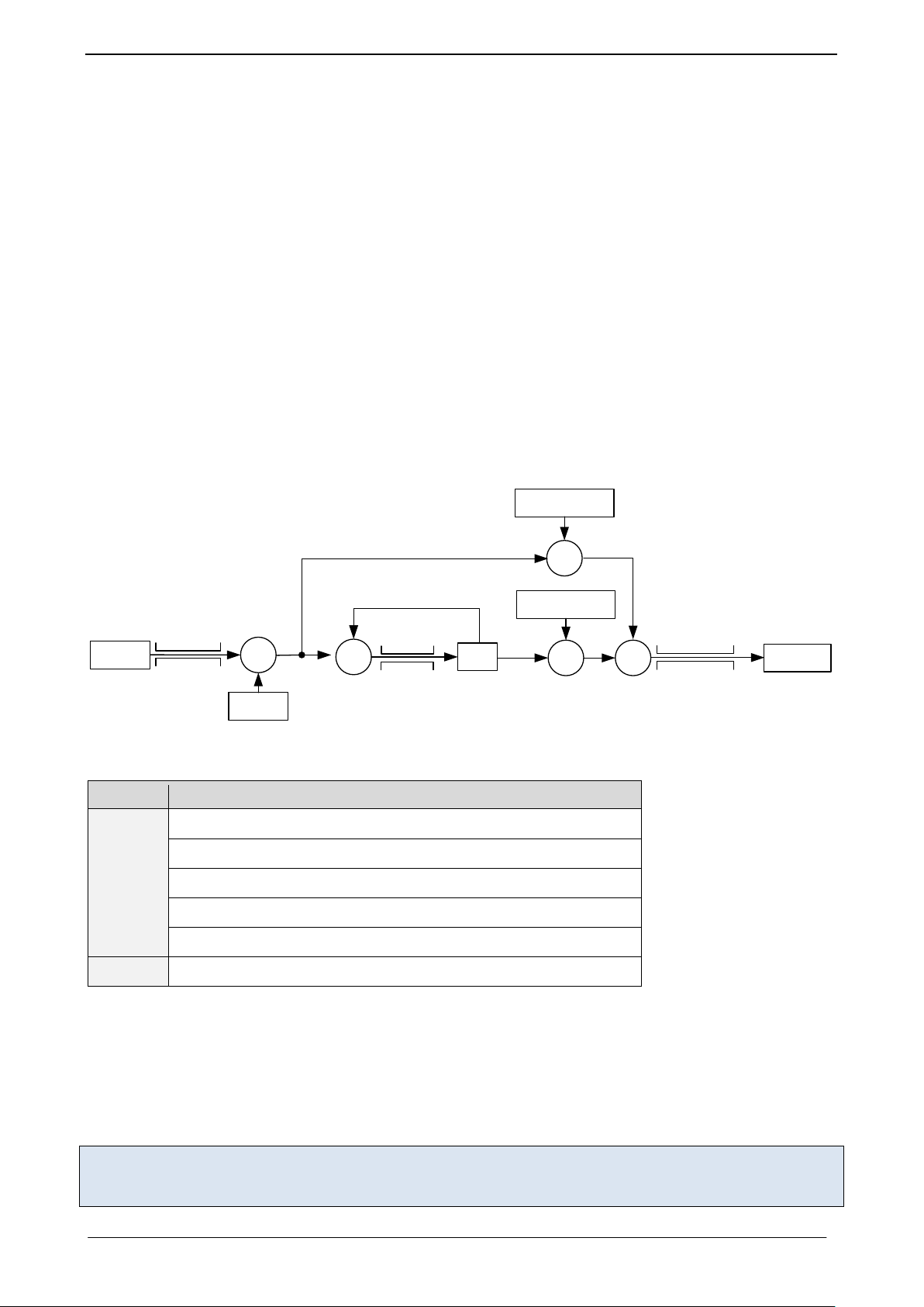
TMCM-1640 TMCL Firmware V2.00 Manual (Rev. 2.00 / 2012-JUL-31) 50
I
ACTUAL
˗
I
TARGET
+
P
PARAM
/256
X
I
PARAM
/65536
X
+
Clip
-32768..
+32767
SVPWM
Clip
I
Max
Clip
I
CLIP
e
SUM
Parameter
Description
I
ACTUAL
Actual motor current (GAP 150)
I
TARGET
Target motor current (SAP 155)
I
Max
Max. motor current (SAP 6)
e
SUM
Error sum for integral calculation (GAP 201)
P
PARAM
Current P parameter (SAP 172)
I
PARAM
Current I parameter (SAP 173)
7.2 Current Regulation
The current regulation mode uses a PID regulator to adjust a desired motor current. This target current can
be set by axis parameter 155. The maximal target current is limited by axis parameter 6.
The PID regulation uses three basic parameters: The P and I value as well as the timing control value.
TIMING CONTROL VALUE
The timing control value (current regulation loop multiplier, axis parameter 134) determines how often the
current regulation is invoked. It is given in multiple of 50µs:
= resulting delay between two current regulation loops
= current regulation loop multiplier parameter
For most applications it is recommended to leave this parameter unchanged at its default of 2*50µs. Higher
values may be necessary for very slow and less dynamic drives.
STRUCTURE OF THE CURRENT REGULATOR
Figure 7.2: Current regulation
PARAMETERIZING THE CURRENT REGULATOR SET
1. Set the P parameter and the I parameter to zero.
2. Start the motor by using a low target current (e.g. 1000 mA).
3. Modify the current P parameter. Start from a low value and go to a higher value, until the actual
current nearly reaches 50% of the desired target current.
4. Do the same with the current I parameter.
For all tests set the motor current limitation to a realistic value, so that your power supply does not become
overloaded during acceleration phases. If your power supply reaches current limitation, the unit may reset or
undetermined regulation results may occur.
www.trinamic.com

TMCM-1640 TMCL Firmware V2.00 Manual (Rev. 2.00 / 2012-JUL-31) 51
v
ACTUAL
v
RAMPGEN
I
PARAM
/ 65536
P
PARAM
/ 256
Clip
I
CLIP
e
SUM
Clip
I
Max
I
TARGET
Clip
V
Max
Parameter
Description
v
ACTUAL
Actual motor velocity (GAP 3)
v
RAMPGEN
Target velocity of ramp generator (SAP 2, GAP 13)
v
Max
Max. target velocity (SAP 4)
e
SUM
Error sum for integral calculation (GAP 229)
P
PARAM
Velocity P parameter (SAP 234)
I
PARAM
Velocity I parameter (SAP 235)
I
Max
Max. target current (SAP 6)
I
Target
Target current for current PID regulator (GAP 155)
7.3 Velocity Regulation
Based on the current regulation the motor velocity can be controlled by the velocity PID regulator.
TIMING CONTROL VALUE
Also, the velocity PID regulator uses a timing control value (PID regulation loop delay, axis parameter 133)
which determines how often the PID regulator is invoked. It is given in multiple of 1ms:
= resulting delay between two PID calculations
= PID regulation loop delay parameter
For most applications it is recommended to leave this parameter unchanged at its default value of 1ms.
Higher values may be necessary for very slow and less dynamic drives.
STRUCTURE OF THE VELOCITY REGULATOR
Figure 7.3: Velocity regulation
PARAMETERIZING THE VELOCITY REGULATOR SET
1. Set the velocity I parameter to zero.
2. Start the motor by using a medium target velocity (e.g. 2000 rpm).
3. Modify the velocity P parameter. Start from a low value and go to a higher value, until the actual
motor speed reaches 80 or 90% of the target velocity.
4. The lasting 10 or 20% speed difference can be reduced by slowly increasing the velocity I
parameter.
www.trinamic.com

TMCM-1640 TMCL Firmware V2.00 Manual (Rev. 2.00 / 2012-JUL-31) 52
n
ACTUAL
n
TARGET
P
PARAM
/256
Clip
V
MAX
V
TARGET
Clip
±65535
Parameter
Description
n
ACTUAL
Actual motor position (GAP 1)
n
TARGET
Target motor position (SAP 0)
P
PARAM
Position P parameter (SAP 130, SAP 230)
V
MAX
Max. allowed velocity (SAP 4)
V
TARGET
New target velocity for ramp generator (GAP 13)
7.4 Velocity Ramp Generator
For a controlled start up of the motor's velocity a velocity ramp generator can be activated/deactivated by
axis parameter 146. The ramp generator uses the maximal allowed motor velocity (axis parameter 4), the
acceleration (axis parameter 11) und the desired target velocity (axis parameter 2) to calculate a ramp
generator velocity for the following velocity PID regulator.
7.5 Position Regulation
Based on current and velocity regulators the TMCM-1640 supports a positioning mode based on encoder or
hall sensor position. During positioning the velocity ramp generator can be activated to enable motor
positioning with controlled acceleration or it can be disabled to support motor positioning with max
allowed speed.
The PID regulation uses two basic parameters: the P regulation and a timing control value.
TIMING CONTROL VALUE
The timing control value (PID regulation loop parameter - axis parameter 133) determines how often the PID
regulator is invoked. It is given in multiple of 1ms:
= the resulting delay between two position regulation loops
= PID regulation loop multiplier parameter
For most applications it is recommended to leave the timing control value unchanged at its default of 1ms.
Higher values may be necessary for very slow and less dynamic drives.
STRUCTURE OF THE POSITION REGULATOR
Figure 7.4: Positioning regulation
PARAMETERIZING THE POSITION REGULATION
Based on the velocity regulator only the position regulator P has to be parameterized.
1. Disable the velocity ramp generator and set position P parameter to zero.
2. Choose a target position and increase the position P parameter until the motor reaches the target
position approximately.
3. Switch on the velocity ramp generator. Based on the max. positioning velocity (axis parameter 4)
and the acceleration value (axis parameter 11) the ramp generator automatically calculates the slow
down point, i.e. the point at which the velocity has to be reduced in order to stop at the desired
target position.
4. Reaching the target position is signaled by setting the position end flag.
www.trinamic.com

TMCM-1640 TMCL Firmware V2.00 Manual (Rev. 2.00 / 2012-JUL-31) 53
|Velocity|
Position
Target position
(set via MVP)
Max. positioning
velocity
MVP target reached distance
Slow-down-distance
Motor regulated by
Velocity PID
Motor regulated by
combination of
Velocity and Position
PID
Acceleration
MVP target
reached velocity
Target reached flag
only set when velocity
and position are in
this area.
NOTE:
- In order to minimize the time until this flag becomes set, the positioning tolerance MVP target reached
distance can be chosen with axis parameter 10.
- Since the motor typically is assumed not to signal target reached when the target was just passed in a
short moment at a high velocity, additionally the maximum target reached velocity (MVP target reached
velocity) can be defined by axis parameter 7.
- A value of zero for axis parameter 7 is the most universal, since it implies that the motor stands still at the
target. But when a fast rising of the position end flag is desired, a higher value for the MVP target reached
velocity parameter will save a lot of time. The best value should be tried out in the actual application.
CORRELATION OF AXIS PARAMETERS 10 AND 7, THE TARGET POSITION, AND THE POSITION END FLAG
Figure 7.5: Positioning algorithm
Depending on motor and mechanics a low oscillation is normal. This can be reduced to at least +/-1 encoder
steps. Without oscillation the regulation cannot keep the position!
www.trinamic.com

TMCM-1640 TMCL Firmware V2.00 Manual (Rev. 2.00 / 2012-JUL-31) 54
8 Temperature Calculation
Axis parameter 152 delivers the actual ADC value of the motor driver. This ADC value can be converted to a
temperature in °C as follows:
≈ 5.31
Example 1: Example 2:
ADC = 1000 ADC = 1200
R
≈ 6.81 R
NTC
NTC
T ≈ 35 T ≈ 42
9 I²t Monitoring
The I²t monitor determines the sum of the square of the motor current over a given time. The integrating
time is motor specific. In the datasheet of the motor this time is described as thermal winding time
constant and can be set for each module using axis parameter 25. The number of measurement values
within this time depends on how often the current regulation and thus the I²t monitoring is invoked. The
value of the actual I²t sum can be read by axis parameter 27. With axis parameter 26 the default value for
the I²t limit can be changed (default: 211200). If the actual I²t sum exceeds the I²t limit of the motor, flag 17
(in axis parameter 156) is set and the motor pwm is set to zero as long as the I²t exceed flag is set. The
actual regulation mode will not be changed. Furthermore, the I²t exceed counter is increased once every
second as long as the actual I²t sum exceeds the I²t limit. The I²t exceed flag can be cleared manually using
parameter 29 but only after the cool down time given by the thermal winding time constant has passed.
The I²t exceed flag will not be reset automatically. The I²t limit can be determined as follows:
is the desired average current
is the thermal winding time constant given by the motor datasheet
Example:
I²t limits for an average current of a) 1A, b) 2A, c) 3A and d) 4A over a thermal winding time of 13,2s.
a)
b)
c)
d)
www.trinamic.com

TMCM-1640 TMCL Firmware V2.00 Manual (Rev. 2.00 / 2012-JUL-31) 55
10 Life Support Policy
TRINAMIC Motion Control GmbH & Co. KG does not authorize or
warrant any of its products for use in life support systems,
without the specific written consent of TRINAMIC Motion Control
GmbH & Co. KG.
Life support systems are equipment intended to support or
sustain life, and whose failure to perform, when properly used in
accordance with instructions provided, can be reasonably
expected to result in personal injury or death.
© TRINAMIC Motion Control GmbH & Co. KG 2012.
Information given in this data sheet is believed to be accurate
and reliable. However neither responsibility is assumed for the
consequences of its use nor for any infringement of patents or
other rights of third parties, which may result from its use.
Specifications are subject to change without notice.
www.trinamic.com

TMCM-1640 TMCL Firmware V2.00 Manual (Rev. 2.00 / 2012-JUL-31) 56
Version
Date
Author
ED – Enrico Dressler
Description
2.00
2012-JUN-10
ED
New FOC firmware
Version
Date
Author
SD – Sonja Dwersteg
Description
2.00
2012-JUL-31
SD
Manual for new Field Orientated Control (FOC) firmware
- Commands SIO and GIO added
- Axis parameters updated
- Motor regulation updated
11 Revision History
11.1 Firmware Revision
11.2 Document Revision
12 References
[TMCM-1640] TMCM-1640 Hardware Manual
[TMCL-IDE] TMCL-IDE User Manual
[TMCM-BLDC] TMCM-BLDC User Manual
[TMC603] TMC603 Datasheet
[QBL4208] QBL4208 Manual
Please refer to our homepage http://www.trinamic.com.
www.trinamic.com
 Loading...