

Trinamic PD1-113-57-SE232, PD2-113-57-SE232, PD3-113-57-SE232, PD4-113-57-SE232, PD1-113-60-SE232 Hardware Manual
...Page 1

PDx-113-57/60-SE
TMCM-113-57/60-SE
Hardware Manual
Version: 1.30
2009-OCT-28
Trinamic Motion Control GmbH & Co KG
Sternstraße 67
D – 20 357 Hamburg, Germany
Phone +49-40-51 48 06 - 0
FAX: +49-40-51 48 06 - 60
http://www.trinamic.com
Page 2

PDx-113-57/60-SE / TMCM-113-57/60-SE Manual (V1.30 / 2009-OCT-28) 2
Table of contents
1 Life support policy ....................................................................................................................................................... 3
2 Features ........................................................................................................................................................................... 4
3 Order codes .................................................................................................................................................................... 5
4 Mechanical and electrical interfacing ..................................................................................................................... 6
4.1 Size of PDx-113-57-SE .......................................................................................................................................... 6
4.2 Size of PDx-113-60-SE .......................................................................................................................................... 7
4.3 Size of electronics (TMCM-113-57/60-SE) ........................................................................................................ 8
4.4 Motor ....................................................................................................................................................................... 9
4.5 Connectors ........................................................................................................................................................... 10
4.5.1 Power connector .......................................................................................................................................... 11
4.5.2 Serial communication connector ............................................................................................................ 11
4.5.3 I/O connector ................................................................................................................................................ 11
4.5.4 Motor connector........................................................................................................................................... 12
4.6 Serial communication interface ..................................................................................................................... 12
4.6.1 RS232 ............................................................................................................................................................... 12
4.6.2 RS485 ............................................................................................................................................................... 13
4.7 Reference switch inputs .................................................................................................................................. 15
4.8 General purpose inputs ................................................................................................................................... 15
4.9 General purpose outputs ................................................................................................................................. 16
5 Functional description .............................................................................................................................................. 17
6 Firmware ....................................................................................................................................................................... 18
7 Torque curves .............................................................................................................................................................. 19
7.1 PD1-113-60-SE ...................................................................................................................................................... 19
7.2 PD2-113-60-SE ...................................................................................................................................................... 20
7.3 PD3-113-60-SE ...................................................................................................................................................... 20
7.4 PD4-113-60-SE ...................................................................................................................................................... 21
8 Operational ratings .................................................................................................................................................... 22
9 Revision history .......................................................................................................................................................... 24
9.1 Document revision ............................................................................................................................................ 24
9.2 Hardware revision ............................................................................................................................................. 24
10 References..................................................................................................................................................................... 24
Copyright © 2009, TRINAMIC Motion Control GmbH & Co. KG
Page 3

PDx-113-57/60-SE / TMCM-113-57/60-SE Manual (V1.30 / 2009-OCT-28) 3
1 Life support policy
TRINAMIC Motion Control GmbH & Co. KG does not
authorize or warrant any of its products for use in life
support systems, without the specific written consent of
TRINAMIC Motion Control GmbH & Co. KG.
Life support systems are equipment intended to support or
sustain life, and whose failure to perform, when properly
used in accordance with instructions provided, can be
reasonably expected to result in personal injury or death.
© TRINAMIC Motion Control GmbH & Co. KG 2009
Information given in this data sheet is believed to be
accurate and reliable. However neither responsibility is
assumed for the consequences of its use nor for any
infringement of patents or other rights of third parties,
which may result form its use.
Specifications are subject to change without notice.
Copyright © 2009, TRINAMIC Motion Control GmbH & Co. KG
Page 4

PDx-113-57/60-SE / TMCM-113-57/60-SE Manual (V1.30 / 2009-OCT-28) 4
2 Features
The PDx-113-57/60-SE is a full mechatronic device consisting of a NEMA 23 (flange size 57mm) or NEMA 24
(flange size 60mm) stepper motor, controller/driver electronics and integrated encoder. The electronics itself
is also available without the motor as TMCM-113-57/60-SE module.
Applications
Compact single-axis stepper motor solutions
Encoder feedback for high reliability operation (-SE option)
Electrical data
Supply voltage: +24V DC nominal (+7V .. +28.5V DC)
Motor current: up-to 2.8A RMS (programmable)
Integrated motor (for PDx-113-57/60-SE only)
Two phase bipolar stepper motor with 2.8A RMS nom. coil current
Holding torque with 57mm motor: 0.55Nm, 1.01Nm, 1.26Nm or 1.89Nm
Holding torque with 60mm motor: 1.1Nm, 1.65Nm, 2.1Nm or 3.1Nm
Integrated encoder (for –SE option only)
Integrated sensOstep™ magnetic encoder (max. 256 increments per rotation) for step-loss detection
under all operating conditions
Integrated motion controller
Motion profile calculation in real-time (TMC428 motion controller)
On the fly alteration of motor parameters (e.g. position, velocity, acceleration)
Integrated bipolar stepper motor driver
Up-to 16 microsteps per full step
High-efficient operation, low power dissipation (TMC249 stepper driver with external MOSFETs)
Dynamic current control
Integrated protection
Integrated stallGuard™ for motor stall detection (e.g. elimination of end switches)
Integrated chopSync™ for high velocity operation
Interfaces
2 inputs for reference switches, 2 general purpose inputs and 2 general purpose outputs
either RS-232 or RS-485 serial communication interfaces
Software
Available with TMCL (both interface options)
stand-alone operation or remote controlled operation
program memory (non volatile) for up-to 2048 TMCL commands
PC-based application development software TMCL-IDE available for free
Please see separate TMCL firmware manual for additional information [TMCL].
Copyright © 2009, TRINAMIC Motion Control GmbH & Co. KG
Page 5
PDx-113-57/60-SE / TMCM-113-57/60-SE Manual (V1.30 / 2009-OCT-28) 5
Order code
Description
Length of unit
PD1-113-57-SE-option
PANdrive with 0.55Nm max./holding torque
60mm
PD2-113-57-SE-option
PANdrive with 1.01Nm max./holding torque
70mm
PD3-113-57-SE-option
PANdrive with 1.26Nm max./holding torque
75mm
PD4-113-57-SE-option
PANdrive with 1.89Nm max./holding torque
95mm
Order code
Description
Length of unit
PD1-113-60-SE-option
PANdrive with 1.10Nm max./holding torque
64mm
PD2-113-60-SE-option
PANdrive with 1.65Nm max./holding torque
75mm
PD3-113-60-SE-option
PANdrive with 2.10Nm max./holding torque
84mm
PD4-113-60-SE-option
PANdrive with 3.10Nm max./holding torque
105mm
Order code
Description
Size of unit
TMCM-113-57/60-SE-option
Single axis bipolar stepper motor controller /
driver electronics with integrated encoder
electronics
board size: 60mm x 60mm
Interface option
Communication interface
232
RS232 interface
485
RS485 interface
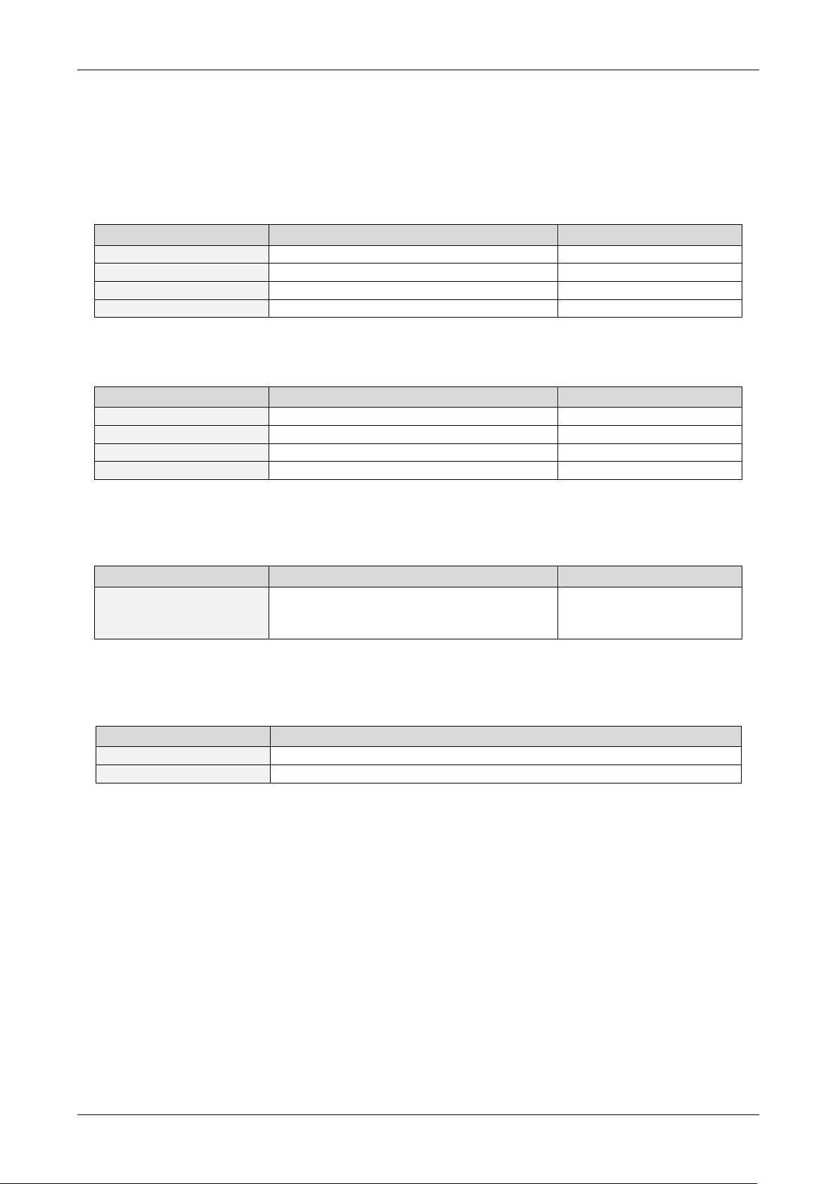
3 Order codes
The PDx-113-57/60-SE is currently available with two different stepper motor series (NEMA23 / 57mm flange
size or) with four stepper motors of different length and holding torque each and two interface options:
With NEMA 23 / 57mm flange size motor:
Table 3.1: Order codes (PDx-113-57-SE)
With NEMA 24 / 60mm flange size motor:
Table 3.2: Order codes (PDx-113-60-SE)
The electronic module TMCM-113-57/60-SE itself is also available with two serial interface options:
Table 3.3: Order codes (TMCM-113-57/60-SE)
Serial interface options:
Table 3.4: Options
For cost critical applications and applications with reduced requirements with regard to position feedback
both versions - with and without motor - are also available without sensOstep™ encoder as PDx-113-57/60
and TMCM-113-57/60 on request.
Copyright © 2009, TRINAMIC Motion Control GmbH & Co. KG
Page 6

PDx-113-57/60-SE / TMCM-113-57/60-SE Manual (V1.30 / 2009-OCT-28) 6
Connectors
17
Length
56.4±138.1±0.025
1.6
5
20.6±1
6,35-0.013 60
38 . 1±0.025
47 . 14±0.2
4 - ø4.6
56 . 4±1
56 . 4±1
6. 3 5-0.013
60 ± 0.5
60 ± 0.5
47 . 14±0.2
Length of motor
PD1
41mm
PD2
51mm
PD3
56mm
PD4
76mm
4 Mechanical and electrical interfacing
4.1 Size of PDx-113-57-SE
Currently, there is a choice between four NEMA 23 / 57mm bipolar stepper motors with different lengths and
different holding torques.
Figure 4.1: Dimensions of PDx-113-57-SE (all values in mm)
Copyright © 2009, TRINAMIC Motion Control GmbH & Co. KG
Page 7

PDx-113-57/60-SE / TMCM-113-57/60-SE Manual (V1.30 / 2009-OCT-28) 7
Length
5
9
38.1±0.025
1.6
24±1
8-0.013
Connectors
17
69 max
20±0.5
7.5±0.2
60±0.5
60 ± 0.5
47 . 14±0.2
60 ± 0.5
38 . 1±0.025
8
47 . 14±0.2
4 - ø4.5
Length of motor
PD1
45.0mm
PD2
56.0mm
PD3
65.0mm
PD4
86.0mm
4.2 Size of PDx-113-60-SE
Currently, there is a choice between four NEMA 24 / 60mm bipolar stepper motors with different lengths and
different holding torques.
Figure 4.2: Dimensions of PDx-113-60-SE (all values in mm)
Copyright © 2009, TRINAMIC Motion Control GmbH & Co. KG
Page 8

PDx-113-57/60-SE / TMCM-113-57/60-SE Manual (V1.30 / 2009-OCT-28) 8
mounting holes
for NEMA 23 /
57mm motors
mounting holes
for NEMA 24 /
60mm motors
Mounting hole 3.2mm
(connected to ground)
Mounting hole 3.2mm
(no electrical connection)
4.3 Size of electronics (TMCM-113-57/60-SE)
The outer shape of the TMCM-113-57/60-SE controller/driver board has been designed in order to fit to the
back bell of a NEMA 24/60mm flange size motor (60mmx60mm). Consequently, the module is a little bit
larger than the motor when being mounted on a standard NEMA 23/57mm motor (figure 4.3).
There are four mounting holes altogether. They have been designed in order to fit to the latest NEMA
23/57mm [QSH5718] and NEMA 24/60mm [QSH6018] stepper motors available from TRINAMIC. Two mounting
holes at opposite corners of the board have been positioned in order to be able to attach it to the back bell
of the NEMA 23/57mm stepper motors and the other two for mounting it to the NEMA 24/60mm stepper
motors.
Figure 4.3: PDx-113-57/60-SE controller/driver board
Copyright © 2009, TRINAMIC Motion Control GmbH & Co. KG
Page 9

PDx-113-57/60-SE / TMCM-113-57/60-SE Manual (V1.30 / 2009-OCT-28) 9
Specifications
Parameter
Units
QSH5718
-41-28-055
-51-28-101
56-28-126
-76-28-189
Number of Leads
N˚ 4 4 4 4
Step Angle
˚ 1.8
1.8
1.8
1.8
Step Angle Accuracy
% 5 5 5
5
Rated Voltage
V
RATED
V 2
2.3
2.5
3.2
Rated Phase Current
I
RMS RATED
A 2.8
2.8
2.8
2.8
Phase Resistance at 20°C
R
COIL
Ω 0.7
0.83
0.9
1.13
Phase Inductance (typ.)
mH
1.4
2.2
2.5
3.6
Holding Torque
Nm
0.55
1.01
1.26
1.89
Rotor Inertia
g cm2
120
275
300
480
Insulation Class
B B B
B
Max. applicable voltage
V 75
75
75
75
Max. radial force
(20mm from front flange)
N 75
75
75
75
Max. axial force
N 15
15
15
15
Weight
kg
0.45
0.65
0.7
1
Length
mm
41
51
56
76
Temp. Rise (rated current,
2 phase on)
˚C
+80 max
+80 max
+80 max
+80 max
Ambient Temperature
˚C
-20 … +50
-20 … +50
-20 … +50
-20 … +50
Specifications
Parameter
Units
QSH6018
-45-28-110
-56-28-165
-65-28-210
-86-28-310
Number of Leads
N˚ 8 8 8 8
Step Angle
˚ 1.8
1.8
1.8
1.8
Rated Voltage
V
RATED
V 2.1
2.52
3.36
4.17
Rated Phase Current
I
RMS RATED
A 2.8
2.8
2.8
2.8
Phase Resistance at 20°C
R
COIL
Ω 0.75
0.9
1.2
1.5
Phase Inductance (typ.)
mH 2 3.6
4.6
6.8
Holding Torque
Nm
1.1
1.65
2.1
3.1
Rotor Inertia
g cm2
275
400
570
840
Insulation Class
B B B
B
Weight
kg
0.6
0.77
1.2
1.4
Ambient Temperature
˚C
-20 … +50
-20 … +50
-20 … +50
-20 … +50
4.4 Motor
Main characteristics of the four different motors available as part of the PDx-113-57-SE:
Table 4.1: NEMA 23 / 57mm technical motor data
Main characteristics of the four different motors available as part of the PDx-113-60-SE:
Table 4.2: NEMA 24 / 60mm technical motor data
Copyright © 2009, TRINAMIC Motion Control GmbH & Co. KG
Page 10
PDx-113-57/60-SE / TMCM-113-57/60-SE Manual (V1.30 / 2009-OCT-28) 10
STOPL
STOPR
GND
VDD
GPO_0
GPO_1
IN_0
IN_1
Left reference switch input
Right reference switch input
Supply and signal ground
Power supply output
General purpose output 0
General purpose output 1
General purpose input 0
General purpose input 1
1
2
3
4
5
6
7
8
GND
RS232_RxD or RS485A / RS485+
GND
Supply and signal ground
Supply and system ground
1
2
3
4
VDD
GND
Power supply input
Supply and system ground
2
1
RS232_TxD or RS485B / RS485-
BB+
AA+
Motor coil B
Motor coil B
Motor coil A
Motor coil A
4
3
2
1
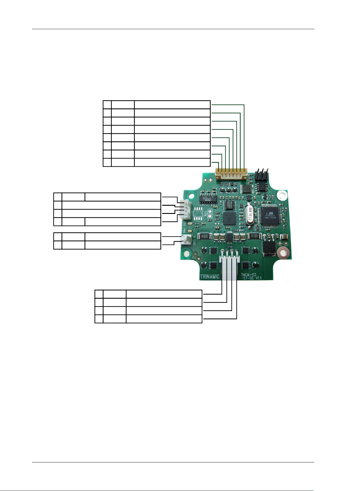
4.5 Connectors
The TMCM-113-57/60-SE has four connectors, a 2-pin connector for power supply, a 4-pin serial
communication interface connector, an 8-pin input/output connector and a 4-pin motor connector (used to
connect the attached motor).
Figure 4.4: TMCM-113-57/60-SE connectors
Copyright © 2009, TRINAMIC Motion Control GmbH & Co. KG
Page 11
PDx-113-57/60-SE / TMCM-113-57/60-SE Manual (V1.30 / 2009-OCT-28) 11
2
1
Pin
Label
Description
1
GND
Module ground (power supply and signal ground)
2
VDD
Power supply input, nom. +24V DC (+7 .. +28.5V DC)
1
4
Pin
RS232
RS485
Description
1
GND
GND
Power and signal ground
2
RS232_RxD
RS485A / RS485+
Serial communication signal
3
RS232_TxD
RS485B / RS485-
Serial communication signal
4
GND
GND
Power and signal ground
18
Pin
Label
Direction
Description
1
STOPL
Input
Left reference switch input
2
STOPR
Input
Right reference switch input
3
GND
Power
Power and signal ground
4
VDD
Output
Power supply output
5
OUT_0
Output
General purpose output (open collector)
6
OUT_1
Output
General purpose output (open collector)
7
IN_0
Input
General purpose input
(+24V compatible)
8
IN_1
Input
General purpose input
(+24V compatible)
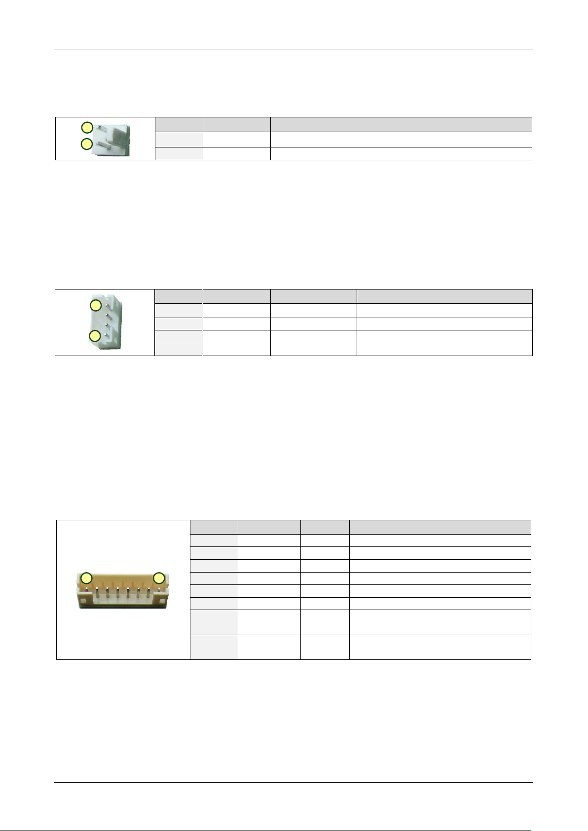
4.5.1 Power connector
A 2-pin Molex 6410 series connector is used for power supply.
Table 4.3: Connector for power
A mating connector together with a cable loom is available as part of the TMCM-113-CABLE cable loom set.
4.5.2 Serial communication connector
A 4-pin JST PH series connector is used for serial communication. Two different communication interface
standards are available with this unit (either or options): RS232 and RS485.
Table 4.4: Connector for communication
Mating connector from JST: PHR-4 (housing) and SPH-002T-P0.5S (crimp contact for AWG #30 to 24 / 0.05mm2
to 0.22mm2 wires).
A mating connector together with a cable loom is available as part of the TMCM-113-CABLE cable loom set.
4.5.3 I/O connector
An 8-pin JST PH series connector is used for general purpose input/output signals and reference switch
inputs.
Table 4.5: Connector for stop switches and general purpose I/O
Mating connector from JST: PHR-8 (housing) and SPH-002T-P0.5S (crimp contact for AWG #30 to 24/0.05mm2
to 0.22mm
A mating connector together with a cable loom is available as part of the TMCM-113-CABLE cable loom set.
Copyright © 2009, TRINAMIC Motion Control GmbH & Co. KG
2
wires).
Page 12

PDx-113-57/60-SE / TMCM-113-57/60-SE Manual (V1.30 / 2009-OCT-28) 12
14
Pin
Label
Direction
Description
1
A+
Output
2-phase stepper motor phase A
2
A-
Output
2-phase stepper motor phase A
3
B+
Output
2-phase stepper motor phase B
4
B-
Output
2-phase stepper motor phase B
4.5.4 Motor connector
A 4-pin Molex 7395 series connector is used for connecting the motor.
Table 4.6: Connector for motor
A mating connector together with a cable loom is available as part of the TMCM-113-CABLE cable loom set.
4.6 Serial communication interface
The PDx-113-57/60-SE is available with two serial interface options: RS232 for point-to-point communication
and RS485 for bus communication. The two different interface options are assembly options – depending on
the desired interface different components are assembled.
4.6.1 RS232
RS232 can be used for serial point-to-point communication. The PDx-113-57/60-SE-232 includes a transceiver
with level converter for true RS232/V24 signal levels (Figure 4.3).
Figure 4.5: RS232 interface option (transceiver/level shifter IC marked red)
When connecting to a master e.g. PC using the RS232 interface please keep in mind that the RS232 transmit
signal wire of the master has to be connected to the RS232 receive signal wire of the board and vice versa.
Connection between PC and PDx-113-57/60-SE:
Copyright © 2009, TRINAMIC Motion Control GmbH & Co. KG
Page 13

PDx-113-57/60-SE / TMCM-113-57/60-SE Manual (V1.30 / 2009-OCT-28) 13
PC
(D-SUB 9pin)
PDx-113-57/60-SE
(Serial communication connector)
Pin
Label
Pin
Label
2
RS232_RxD
3
RS232_TxD
3
RS232_TxD
2
RS232_RxD
5
GND
1, 4
GND
c:>
node
1
node
n - 1
node
n
Host
Slave Slave Slave
RS485
termination
resistor
(120 Ohm)
termination
resistor
(120 Ohm)
}
keep distance as
short as possible
Table 4.7: RS232 Connection PC <-> PDx-113-57/60-SE
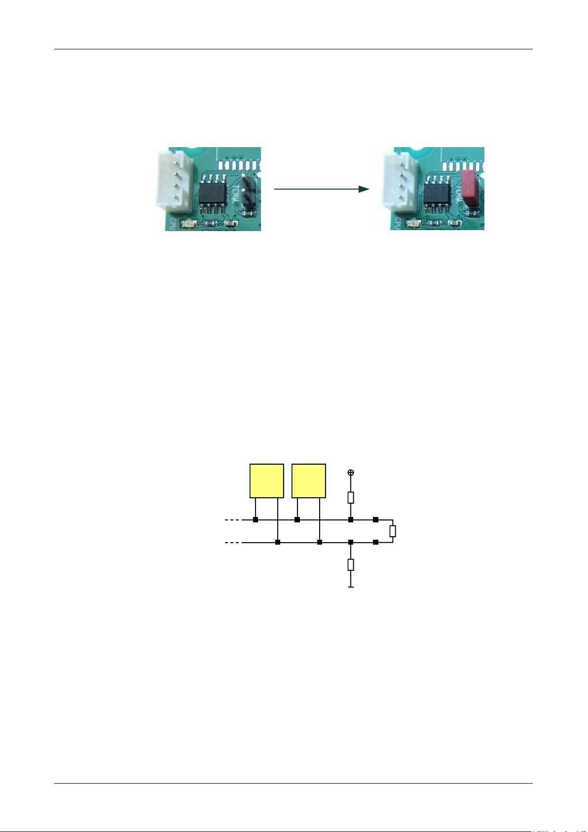
4.6.2 RS485
RS485 can be used for serial bus communication. The PDx-113-57/60-SE-485 includes a transceiver and a
termination resistor which can be activated for modules placed at one end of the communication bus using
an on-board jumper (Figure 4.4).
Figure 4.6: RS485 interface option (transceiver and termination header marked red)
For proper operation of the RS485 bus the following items should be taken into account when setting up an
RS485 network:
1. BUS STRUCTURE: The network topology should follow a bus structure as closely as possible. That is,
the connection between each node and the bus itself should be as short as possible. Basically, it
should be short compared to the length of the bus.
Copyright © 2009, TRINAMIC Motion Control GmbH & Co. KG
Figure 4.7: Bus structure
Page 14
PDx-113-57/60-SE / TMCM-113-57/60-SE Manual (V1.30 / 2009-OCT-28) 14
Set jumper for RS485
bus termination
node
n - 1
node
n
Slave Slave
termination
resistor
(120 Ohm)
+5V
GND
pull-up (1k)
pull-down (1k)
RS485- / RS485B
RS485+ / RS485A
2. BUS TERMINATION: Especially for longer busses and/or multiple nodes connected to the bus and/or
high communication speeds, the bus should be properly terminated at both ends. The PDx-11357/60-SE-485 integrates a 120 Ohm termination resistor that can be placed between both RS485 bus
wires by setting a jumper:
Figure 4.8: Bus termination
3. NUMBER OF NODES: The RS-485 electrical interface standard (EIA-485) allows up-to 32 nodes to be
connected to a single bus. The bus transceiver used for the PDx-113-57/60-SE-485 units
(SN65HVD3082ED) has just 1/8 of the standard bus load and allows a maximum of 256 units to be
connected to a single RS485 bus.
4. NO FLOATING BUS LINES: Avoid floating bus lines while neither the host/master nor one of the
slaves along the bus line is transmitting data (all bus nodes switched to receive mode). Floating bus
lines may lead to communication errors. In order to ensure valid signals on the bus it is
recommended to use a resistor network connecting both bus lines to well defined logic levels. In
contrast to the termination resistors this network is normally required just once for a bus. Certain
RS485 interface converters available for a PC already include these additional resistors (e.g. USB-2485 [USB-2-485]).
Copyright © 2009, TRINAMIC Motion Control GmbH & Co. KG
Figure 4.9: Resistor network to avoid floating bus lines
Page 15

PDx-113-57/60-SE / TMCM-113-57/60-SE Manual (V1.30 / 2009-OCT-28) 15
STOPL
1k
10k
+5V
1nF
GND
STOPR
1k
10k
+5V
1nF
GND
IN_0
10k
10k
GND
+5V
GND
IN_1
10k
10k
GND
+5V
GND
4.7 Reference switch inputs
There are 2 reference/stop switch inputs (STOPL / STOPR). Both inputs offer an internal pull-up resistor (1k)
and accept voltages between 0 and +5V.
Figure 4.10: Reference/stop switch inputs STOPL, STOPR
4.8 General purpose inputs
There are 2 general purpose inputs (IN_0 / IN_1). Both inputs offer internal voltage divider and voltage
limiter and accept input voltages between 0 and +24V. The voltage divider resistors act as pull-down
resistors, also. Both inputs accept digital and analogue signals (depending on software configuration).
Figure 4.11: General purpose inputs IN_o, IN_1
Copyright © 2009, TRINAMIC Motion Control GmbH & Co. KG
Page 16

PDx-113-57/60-SE / TMCM-113-57/60-SE Manual (V1.30 / 2009-OCT-28) 16
10k
GND
VDD
OUT_0
BC847
10k
GND
VDD
OUT_1
BC847
4.9 General purpose outputs
There are 2 general purpose outputs (OUT_0 / OUT_1). Both outputs are open collector outputs and can drive
loads up-to 100mA. Especially for inductive loads a freewheeling diode to supply voltage (VDD) has been
included. This is also the reason why the external voltage at the general purpose outputs - when the
outputs are switched off - should not be higher than the supply voltage of the module + approx. 0.5V.
Figure 4.12: General purpose outputs OUT_0, OUT_1
Copyright © 2009, TRINAMIC Motion Control GmbH & Co. KG
Page 17

PDx-113-57/60-SE / TMCM-113-57/60-SE Manual (V1.30 / 2009-OCT-28) 17
5V Power Supply
RS232
or
RS485
24V
PD-113-57/60-SE
progammable
Motion
Controller
with TMC428
High Power
Driver
TMC249
TMCL
Memory
sensOstepTM
Encoder
MOSFET
Driver
Stage
Step
Motor
5 Functional description
The PD-113-57/60-SE is a full mechatronic solution including a 57 or 60 mm flange motor (NEMA23/NEMA24).
It combines a convenient controller electronic and a sensOstep™ encoder with a range of different motor
types and can be controlled via RS-232 or RS485 interface. The chopSync™ feature allows high velocity
operation avoiding resonances. The PD-113-57/60-SE comes with the PC based software development
environment TMCL-IDE for the Trinamic Motion Control Language (TMCL). Using predefined TMCL high level
commands like „move to position“ or „constant rotation“ a rapid and fast development of motion control
applications is guaranteed. Communication traffic is kept very low since all time critical operations, e.g. ramp
calculation are performed onboard. The stepper driver / controller module is available without the
electronics also as TMCM-113-57/60-SE.
Figure 5.1: Main parts of the PD-113-57/60-SE
Copyright © 2009, TRINAMIC Motion Control GmbH & Co. KG
Page 18

PDx-113-57/60-SE / TMCM-113-57/60-SE Manual (V1.30 / 2009-OCT-28) 18
6 Firmware
Currently, the standard TMCL firmware is available for both interface options and is supplied as default
firmware. Please refer to the TMCL firmware manual for this unit for more details [TMCL].
Copyright © 2009, TRINAMIC Motion Control GmbH & Co. KG
Page 19

PDx-113-57/60-SE / TMCM-113-57/60-SE Manual (V1.30 / 2009-OCT-28) 19
7 Torque curves
The following torque curves have been measured using the PANdrive PDx-113-60-SE with all four stepper
motors available as part of this unit. The four different stepper motors all offer the same max. coil current
but, differ with respect to holding torque, motor length, coil resistance and inductivity – to name a few. As
rule of thumb, more holding torque means more copper, longer or larger motor, more coil resistance and
higher inductivity which limits the max. reachable velocity at the same supply voltage. All measurements
were taken at +24V driver supply voltage and max. motor current.
The figures below include torque curves for microstep operation and full step operation. With full step
mode it is possible to reach higher velocities whereas resonances normally prevent any smooth operation at
lower speeds (see torque curves below). Therefore, TMCL firmware offers programmable automatic switch
over between microstep operation at lower speeds and full-step operation at higher speed in order to take
advantage of both modes (please see TMCL firmware manual, axis parameter 211).
7.1 PD1-113-60-SE
The PD1-113-60-SE is the most compact version of this PANdrive version with the shortest NEMA 24 / 60mm
stepper motor.
Figure 7.1: PD1-113-60-SE torque curve
Copyright © 2009, TRINAMIC Motion Control GmbH & Co. KG
Page 20

PDx-113-57/60-SE / TMCM-113-57/60-SE Manual (V1.30 / 2009-OCT-28) 20
7.2 PD2-113-60-SE
For applications where more torque is required than available with the PD1-113-60-SE, the PD2-113-60-SE
might be an option.
Figure 7.2: PD2-113-60-SE torque curve
7.3 PD3-113-60-SE
For applications where more torque is required than available with the PD2-113-60-SE, the PD3-113-60-SE
might be an option.
Figure 7.3: PD3-113-60-SE torque curve
Copyright © 2009, TRINAMIC Motion Control GmbH & Co. KG
Page 21

PDx-113-57/60-SE / TMCM-113-57/60-SE Manual (V1.30 / 2009-OCT-28) 21
7.4 PD4-113-60-SE
For applications where more torque is required than available with the PD3-113-60-SE, the PD4-113-60-SE
might be an option. The PD4-113-60-SE is the version with highest holding torque and the longest stepper
motor available for this PANdrive series.
Figure 7.4: PD4-113-60-SE torque curve
Copyright © 2009, TRINAMIC Motion Control GmbH & Co. KG
Page 22

PDx-113-57/60-SE / TMCM-113-57/60-SE Manual (V1.30 / 2009-OCT-28) 22
Symbol
Parameter
Min
Type
Max
Unit
VDD
Power supply voltage for operation
7
24
28.5
V
I
COIL_peak
Motor coil current for sine wave
peak (chopper regulated, adjustable
via software)
0 4 *)
A
I
COIL_RMS
Continuous motor current (RMS)
0 2.8 *)
A
I
SUPPLY
Power supply current
<< I
COIL
1.4 * I
COIL
A
T
ENV
Environment temperature at rated
current (no forced cooling required)
-20
+40 **)
°C
Environment temperature at 80% of
rated current or 50% duty cycle
(no forced cooling required)
-20 +60
°C
8 Operational ratings
The operational ratings shown below should be used as design values. In no case should the maximum
values be exceeded during operation.
Table 8.1: General operational ratings of the module
*) Please note: only PDx-113-57/60-SE and TMCM-113-57/60-SE with pcb version 1.2 or newer support specified
max. current over full temperature range. Older / pre-series versions may be limited with regard to
temperature range and / or max. motor current.
**) Test set-up / procedure: PANdrive PD4-113-60-SE mounted to a metal base plate in order to keep stepper
motor temperature within limits for the motor during test (table 4.2) / test inside climate chamber with
approx. 53l volume / no forced air convection during test / test duration at least 30min.
Please note: motor temperature should always be kept below upper limit for the motor - that is, motor /
PANdrive should be mounted to an appropriate metal / cooling plate or frame. Especially, the longer
available stepper motor which are part of the PD4-113-57-SE or PD4-113-60-SE may easily reach 100°C or
above when operated at full current over long time without being mounted to any heat-conducting
structure or forced air convection. In case the TMCM-113-57/60-SE electronic module is mounted close to the
motor as with the PANdrives, the motor might substantially heat up the electronics and limit the maximum
environmental temperature during operation. The unit may be operated at higher environmental
temperatures than specified when the duty cycle of the motor and / or the motor current is reduced or in
case the TMCM-113-57/60-SE electronic module is mounted separately from the motor.
Copyright © 2009, TRINAMIC Motion Control GmbH & Co. KG
Page 23

PDx-113-57/60-SE / TMCM-113-57/60-SE Manual (V1.30 / 2009-OCT-28) 23
Symbol
Parameter
Min
Type
Max
Unit
V
STOPL/R
Input voltage for STOPL/R
0 5
V
V
STOPL/R_L
Low level voltage for STOPL/R
0 1.2
V
V
STOPL/R_H
High level voltage for STOPL/R
(internal 1k pull-up)
1.9 5
V
V
IN_0/1_digital
Input voltage for IN_0 and IN_1
when used as digital input
0 24
V
V
IN_0/1_analogue
Input voltage for IN_0 and IN_1
when used as analogue input
0 10
V
V
IN_0/1_L
Low level voltage for IN_0 and IN_1
when used as digital input
(internal 20k pull-down)
0 2
V
V
IN_0/1_H
High level voltage for IN_0 and IN_1
when used as digital input
6 24
V
V
OUT_0/1
Voltage at open collector output
0
VDD + 0.5 *)
V
I
OUT_0/1
Output sink current
100
mA
Symbol
Parameter
Min
Type
Max
Unit
N
RS485
Number of nodes connected to
single RS485 network
256
Table 8.2: Operational ratings of the general purpose inputs/outputs
*) limited to module supply voltage + 0.5V due to integrated freewheeling diode between general purpose
output and module supply voltage
Table 8.3: Operational ratings of the PS485 interface
Copyright © 2009, TRINAMIC Motion Control GmbH & Co. KG
Page 24

PDx-113-57/60-SE / TMCM-113-57/60-SE Manual (V1.30 / 2009-OCT-28) 24
Version
Date
Author
Description
1.00
2008-OCT-20
GE
Initial version
1.10
2008-DEC-19
SD
Dimensions of the PANdrives and functional description added
1.20
2009-MAY-13
SD
PD3-113-57-SE and PD4-113-57-SE added
1.30
2009-OCT-28
GE
New hardware version and torque curves added
Version
Date
Description
1.00
2008-JUL-25
First three prototypes
1.10
2008-SEP-24
Minor corrections, start of series production
1.20
2009-JUN-10
Optimisation of thermal design
1.30
2009-AUG-05
Encoder connection corrected, series production version
9 Revision history
9.1 Document revision
Table 9.1: Document revision
9.2 Hardware revision
Table 9.2: Hardware revision
10 References
[TMCL] PDx-113-57/60-SE TMCL firmware manual (see http://www.trinamic.com)
[QSH5718] 57mm stepper motor reference manual (see http://www.trinamic.com)
[QSH6018] 60mm stepper motor reference manual (see http://www.trinamic.com)
[USB-2-485] USB-2-485 interface converter reference manual
(see http://www.trinamic.com)
Copyright © 2009, TRINAMIC Motion Control GmbH & Co. KG
 Loading...