


Stepper Motor with
Controller / Driver
0.7A RMS / 24V DC
RS485 Interface
MODULE FOR STEPPER MOTORS MODULE
Hardware Version V1.2
HARDWARE MANUAL
+
+ +
+
TMCM-1021
UNIQUE FEATURES:
TRINAMIC Motion Control GmbH & Co. KG
Hamburg, Germany
www.trinamic.com

TMCM-1021 V1.2 Hardware Manual (Ref. 1.00 / 2012-MAR-09) 2
Table of Contents
1 Features ........................................................................................................................................................................... 3
2 Order Codes ................................................................................................................................................................... 5
3 Mechanical and Electrical Interfacing ..................................................................................................................... 6
3.1 Size of Board ........................................................................................................................................................ 6
3.2 Connectors ............................................................................................................................................................. 7
3.2.1 Power, Communication and I/O Connector .......................................................................................... 8
3.2.2 Motor Connector ............................................................................................................................................ 8
3.3 Power Supply ....................................................................................................................................................... 9
3.4 Communication .................................................................................................................................................... 9
3.4.1 RS485 ................................................................................................................................................................ 9
3.5 Inputs and Outputs .......................................................................................................................................... 10
3.5.1 Multi-purpose Inputs .................................................................................................................................. 10
3.5.2 General Purpose Outputs .......................................................................................................................... 11
4 Reset to Factory Defaults ......................................................................................................................................... 12
5 On-board LED ............................................................................................................................................................... 12
6 Operational Ratings ................................................................................................................................................... 13
7 Functional Description .............................................................................................................................................. 14
8 Life Support Policy ..................................................................................................................................................... 15
9 Revision History .......................................................................................................................................................... 16
9.1 Document Revision ........................................................................................................................................... 16
9.2 Hardware Revision ............................................................................................................................................ 16
10 References .................................................................................................................................................................... 16
www.trinamic.com

TMCM-1021 V1.2 Hardware Manual (Ref. 1.00 / 2012-MAR-09) 3
1 Features
The TMCM-1021 is a single axis controller/driver module for 2-phase bipolar stepper motors with state of the
art feature set. It is highly integrated, offers a convenient handling and can be used in many decentralized
applications. The module can be mounted on the back of NEMA11 (28mm flange size) and has been
designed for coil currents up to 0.7A RMS and 24V DC supply voltage. With its high energy efficiency from
TRINAMIC’s coolStep™ technology cost for power consumption is kept down. The TMCL™ firmware allows for
both, standalone operation and direct mode.
MAIN CHARACTERISTICS
Highlights
- Motion profile calculation in real-time
- On the fly alteration of motor parameters (e.g. position, velocity, acceleration)
- High performance microcontroller for overall system control and serial communication protocol
handling
- For position movement applications, where larger motors do not fit and higher torques are not
required
Bipolar stepper motor driver
- Up to 256 microsteps per full step
- High-efficient operation, low power dissipation
- Dynamic current control
- Integrated protection
- stallGuard2 feature for stall detection
- coolStep feature for reduced power consumption and heat dissipation
Encoder
- sensOstep magnetic encoder (max. 1024 increments per rotation) e.g. for step-loss detection under all
operating conditions and positioning supervision
Interfaces
- Up to 4 multi-purpose inputs (2 shared with outputs)
- 2 general purpose outputs
- RS485 2-wire communication interface
Software
- TMCL: standalone operation or remote controlled operation,
program memory (non volatile) for up to 876 TMCL commands, and
PC-based application development software TMCL-IDE available for free.
Electrical and mechanical data
- Supply voltage: +24V DC nominal (9… 28V DC)
- Motor current: up to 0.7A RMS (programmable)
Refer to separate TMCL Firmware Manual, too.
www.trinamic.com
TMCM-1021 V1.2 Hardware Manual (Ref. 1.00 / 2012-MAR-09) 4
Load
[Nm]
stallGuard2
Initial stallGuard2
(SG) value: 100%
Max. load
stallGuard2 (SG) value: 0
Maximum load reached.
Motor close to stall.
Motor stalls
0
0,1
0,2
0,3
0,4
0,5
0,6
0,7
0,8
0,9
0 50 100 150 200 250 300 350
Efficiency
Velocity [RPM]
Efficiency with coolStep
Efficiency with 50% torque reserve
TRINAMICS UNIQUE FEATURES – EASY TO USE WITH TMCL
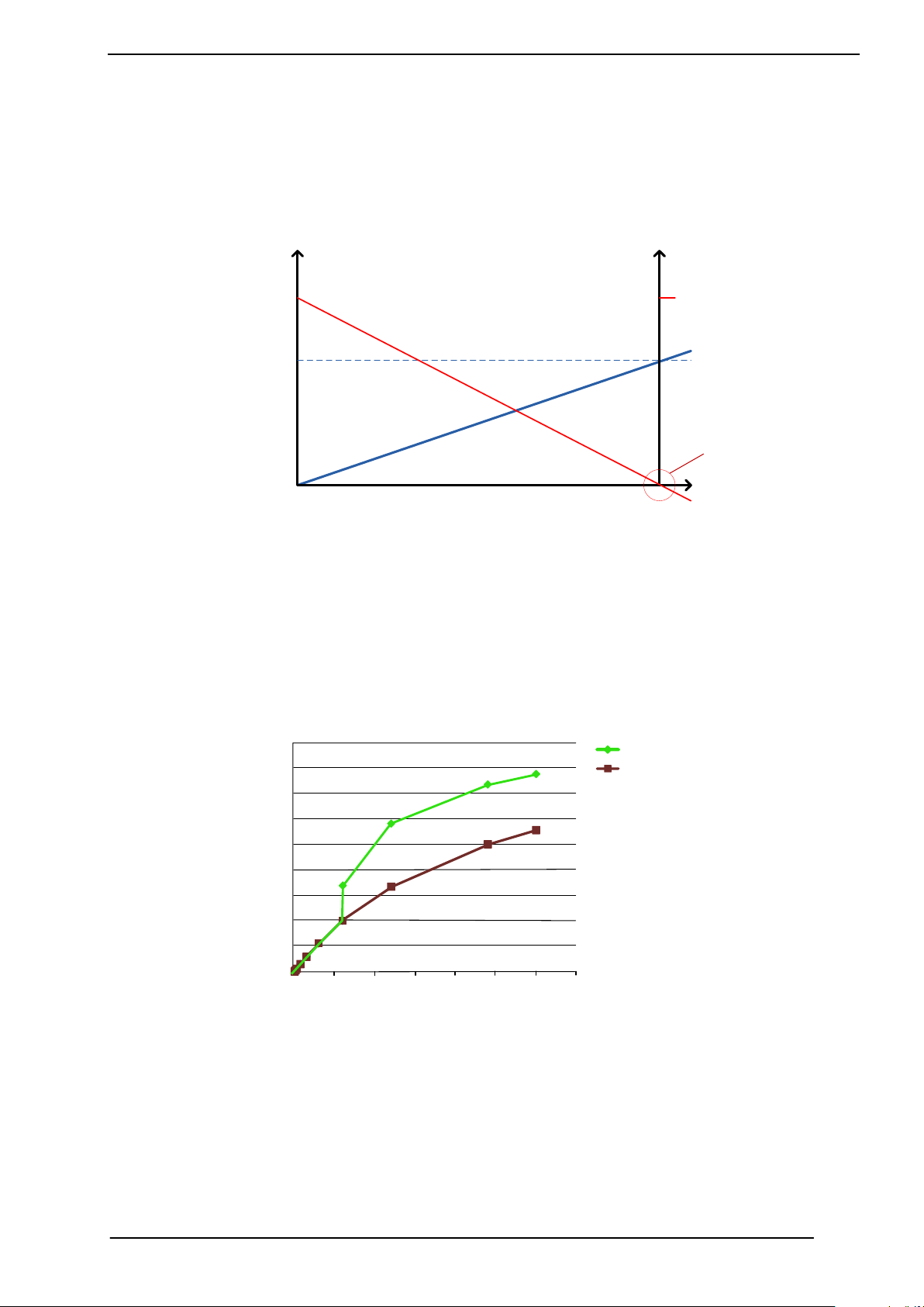
stallGuard2™ stallGuard2 is a high-precision sensorless load measurement using the back EMF on the
coils. It can be used for stall detection as well as other uses at loads below those which
stall the motor. The stallGuard2 measurement value changes linearly over a wide range of
load, velocity, and current settings. At maximum motor load, the value goes to zero or near
to zero. This is the most energy-efficient point of operation for the motor.
Figure 1.1 stallGuard2 load measurement SG as a function of load
coolStep™ coolStep is a load-adaptive automatic current scaling based on the load measurement via
stallGuard2 adapting the required current to the load. Energy consumption can be reduced
by as much as 75%. coolStep allows substantial energy savings, especially for motors which
see varying loads or operate at a high duty cycle. Because a stepper motor application
needs to work with a torque reserve of 30% to 50%, even a constant-load application allows
significant energy savings because coolStep automatically enables torque reserve when
required. Reducing power consumption keeps the system cooler, increases motor life, and
allows reducing cost.
www.trinamic.com
Figure 1.2 Energy efficiency example with coolStep

TMCM-1021 V1.2 Hardware Manual (Ref. 1.00 / 2012-MAR-09) 5
Order code
Description
Size of unit
TMCM-1021
Single axis bipolar stepper motor controller/driver
electronics with integrated encoder electronics
28mm x 28mm
Order code
Description
TMCM-1021-CABLE
Cable loom for TMCM-1021
- 1x cable loom for power, communication and I/O connector
(cable length approx. 200mm)
- 1x cable loom for motor connector (cable length ca. 200mm)
2 Order Codes
Table 2.2: Order codes
A cable loom set is available for this module:
Table 2.5: Cable loom order code
www.trinamic.com

TMCM-1021 V1.2 Hardware Manual (Ref. 1.00 / 2012-MAR-09) 6
PCB outline
25.5mm
R 2.5mm
27mm
27mm
25.5mm
28mm
28mm
28mm x 28mm
Motor backbell
R 2mm
R 1.3mm
3 Mechanical and Electrical Interfacing
3.1 Size of Board
The board with the controller/driver electronics has an overall size of 28mm x 28mm in order to fit on the
back side of a NEMA11 (28mm flange size) stepper motor. The printed circuit board outline is marked green
in the following figure:
Figure 3.1: Board dimensions and position of mounting holes
www.trinamic.com

TMCM-1021 V1.2 Hardware Manual (Ref. 1.00 / 2012-MAR-09) 7
1
1
Power / Communication / IOs
Motor
Label
Connector type
Mating connector type
Power,
communication
and I/O
JST B8B-PH-K-S
(JST PH series, 8pins, 2mm pitch)
Connector housing: JST PHR-8
Contacts: JST SPH-002T-P0.5S
Wire: 0.22mm2, AWG 24
Motor
JST B4B-PH-K-S
(JST PH series, 4pins, 2mm pitch)
Connector housing: JST PHR-4
Contacts: JST SPH-002T-P0.5S
Wire: 0.22mm2, AWG 24
3.2 Connectors
The TMCM-1021 has two connectors, an 8-pin power and input/output connector and a 4-pin motor
connector (used to connect the attached motor).
Figure 3.2: TMCM-1021 connectors
Overview of connector and mating connector types:
Table 3.2: Connectors and mating connectors, contacts and applicable wire
www.trinamic.com

TMCM-1021 V1.2 Hardware Manual (Ref. 1.00 / 2012-MAR-09) 8
Pin
Label
Direction
Description
1
GND
Power (GND)
GND
2
VDD
Power (Supply)
VDD (+9V…+28V)
3
RS485+
Bidirectional
RS485 interface, diff. signal (non-inverting)
4
RS485-
Bidirectional
RS485 interface, diff. signal (inverting)
5
IN_0
Input
Digital input (+24V compatible)
Alternate function 1: step input
Alternate function 2: left stop switch
6
IN_1
Input
Digital input (+24V compatible)
Alternate function 1: direction input
Alternate function 2: right stop switch
7
OUT_0 / IN_2
Output / Input
Open drain output with freewheeling diode
(max. 100mA)
Alternate function 1:
digital input (+24V compatible)
Alternate function 2:home switch
8
OUT_1 / IN_3
Output / Input
Open drain output with freewheeling diode
(max. 100mA)
Alternate function 1: digital input
(+24V compatible)
Alternate function 2: analog input
Pin
Label
Direction
Description
1
OB2
Output
Pin 2 of motor coil B
2
OB1
Output
Pin 1 of motor coil B
3
OA2
Output
Pin 2 of motor coil A
4
OA1
Output
Pin 1 of motor coil A
Example for connecting a motor.
TMCM-1021
QSH2818 Motor
Motor connector pin
Cable colour
Coil
Description
1
Blue
B-
Motor coil B pin 2
2
Red B Motor coil B pin 1
3
Green
A-
Motor coil A pin 2
4
Black
A
Motor coil A pin 1
M
black
green
red
blue
A
B
3.2.1 Power, Communication and I/O Connector
An 8-pin JST PH-series 2mm pitch single row connector is used for power supply, RS485 serial
communication and additional multi-purpose inputs and outputs.
Table 3.3: Power, communication and I/O connector
3.2.2 Motor Connector
The motor connector is used for connecting the four motor wires to the electronics.
Table 3.4: Motor connector
www.trinamic.com
TMCM-1021 V1.2 Hardware Manual (Ref. 1.00 / 2012-MAR-09) 9
c:>
node
1
node
n
- 1
node
n
Host
Slave Slave Slave
RS485
termination
resistor
(120 Ohm)
termination
resistor
(120 Ohm)
}
keep distance as
short as possible
3.3 Power Supply
For proper operation care has to be taken with regard to power supply concept and design. Due to space
restrictions the TMCM-1021 includes just about 20µF/35V of supply filter capacitors. These are ceramic
capacitors which have been selected for high reliability and long life time. The module includes a 28V
suppressor diode for over-voltage protection. There is no reverse polarity protection. The module will short
any reversed supply voltage due to internal diodes of the driver transistors.
It is absolutely necessary that the power supply voltage is kept below the upper limit of 28V under all
circumstances (please see also chapter 6, operating values). Otherwise the driver electronics might be
seriously damaged! Especially, when the selected operating voltage is near the upper limit a regulated
power supply is highly recommended.
It is recommended to connect an electrolytic capacitor of significant size (e.g. 470µF/35V) to the power
supply lines next to the TMCM-1021!
Rule of thumb for size of electrolytic capacitor:
In addition to power stabilization (buffer) and filtering this added capacitor will also reduce any voltage
spikes which might otherwise occur from a combination of high inductance power supply wires and the
ceramic capacitors. In addition it will limit slew-rate of power supply voltage at the module. The low ESR of
ceramic-only filter capacitors may cause stability problems with some switching power supplies.
3.4 Communication
3.4.1 RS485
For remote control and communication with a host system the TMCM-1021 provides a two wire RS485 bus
interface. For proper operation the following items should be taken into account when setting up an RS485
network:
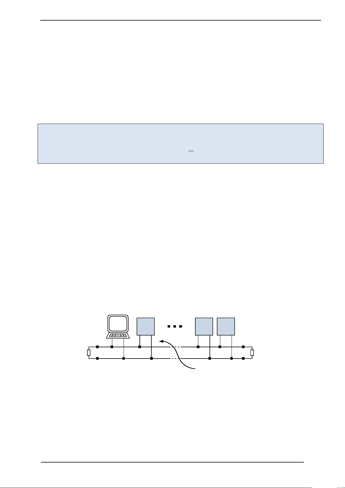
1. BUS STRUCTURE:
The network topology should follow a bus structure as closely as possible. That is, the connection
between each node and the bus itself should be as short as possible. Basically, it should be short
compared to the length of the bus.
Figure 3.5: Bus structure
2. BUS TERMINATION:
Especially for longer busses and/or multiple nodes connected to the bus and/or high communication
speeds, the bus should be properly terminated at both ends. The TMCM-1021 does not integrate any
termination resistor. Therefore, 120 Ohm termination resistors at both ends of the bus have to be
added externally.
www.trinamic.com

TMCM-1021 V1.2 Hardware Manual (Ref. 1.00 / 2012-MAR-09) 10
node
n - 1
node
n
Slave Slave
termination
resistor
(120 Ohm)
+5V
GND
pull-up (1k)
pull-down (1k)
RS485- / RS485B
RS485+ / RS485A
+3.3V
IN_0
IN_1
IN_2
IN_3
microcontroller
and TMC262
10k
10k
1nF
GND
GND GND
3. NUMBER OF NODES:
The RS485 electrical interface standard (EIA-485) allows up to 32 nodes to be connected to a single
bus. The bus transceiver used on the TMCM-1021 units (SN65HVD3082ED) has just 1/8th of the
standard bus load and allows a maximum of 256 units to be connected to a single RS485 bus.
4. NO FLOATING BUS LINES:
Avoid floating bus lines while neither the host/master nor one of the slaves along the bus line is
transmitting data (all bus nodes switched to receive mode). Floating bus lines may lead to
communication errors. In order to ensure valid signals on the bus it is recommended to use a
resistor network connecting both bus lines to well defined logic levels. In contrast to the
termination resistors this network is normally required just once per bus. Certain RS485 interface
converters available for PCs already include these additional resistors (e.g. USB-2-485).
Figure 3.6: Bus lines with resistor network
3.5 Inputs and Outputs
3.5.1 Multi-purpose Inputs
The eight pin connector of the TMCM-1021 provides four general purpose inputs IN_0, IN_1, IN_2 and IN_3.
The first two inputs have dedicated connector pins while the other two share pins with two general
purpose outputs.
All four inputs are protected using voltage resistor dividers together with limiting diodes against voltages
below 0V (GND) and above +3.3V DC (see figure below).
Figure 3.7: General purpose inputs
www.trinamic.com

TMCM-1021 V1.2 Hardware Manual (Ref. 1.00 / 2012-MAR-09) 11
Label
(connector pin)
Default Function
Alternate function 1
Alternate function 2
IN_0 (5)
Digital input
Step signal input
(connected to TMC262 step input)
Left stop switch
IN_1 (6)
Digital input
Direction signal input
(connected to TMC262 direction input)
Right stop switch
OUT_0 / IN_2 (7)
Output
Digital input
Home switch
OUT_1 / IN_3 (8)
Output
Digital input
Analog input
(0… +6.6V, 12bit resolution)
VDD
OUT_0 / IN_2
OUT_1 / IN_3
microcontroller
GND
+3.3V
microcontroller
10k
10k
1nF
GND
GND GND
The four inputs have alternate functionality depending on configuration in software. The following functions
are available:
Table 3.5: Multi-purpose inputs / alternate functions
All four inputs are connected to the on-board processor and can be used as general purpose digital inputs.
Using the alternate functionality of IN_0 and IN_1 it is possible to control the on-board stepper motor driver
with the help of an external stepper motor controller using step and direction signals. For the step and
direction signals the signal levels are the same as for the general purpose digital inputs.
IN_3 can be used as analog input, also. A 12bit analog to digital converter integrated in the microcontroller
will convert any analog input voltage between 0 and +6.6V to a digital value between 0 and 4095 then.
3.5.2 General Purpose Outputs
The eight pin connector of the TMCM-1021 provides two general purpose outputs. These two outputs are
open-drain outputs and can sink up to 100mA each. The outputs of the N-channel MOSFET transistors are
connected to freewheeling diodes each for protection against voltage spikes especially from inductive loads
(relais etc.).
Both outputs OUT_0 and OUT_1 share pins with two of the four inputs (IN_2 resp. IN_3).
Please take into account the 20k (2x 10k in series) resistance to ground (transistor not active) of the input
voltage divider (figure 4.8) when designing the external “load” circuit.
www.trinamic.com
Figure 3.8: General purpose outputs

TMCM-1021 V1.2 Hardware Manual (Ref. 1.00 / 2012-MAR-09) 12
Short these two pads
Green LED
4 Reset to Factory Defaults
It is possible to reset the TMCM-1021 to factory default settings without establishing a communication link.
This might be helpful in case communication parameters of the preferred interface have been set to
unknown values or got accidentally lost.
For this procedure two pads on the bottom side of the board have to be shortened (see Figure 4.1).
Please perform the following steps:
1. Power supply off and USB cable disconnected
2. Short two pads as marked in Figure 4.1
3. Power up board (power via USB is sufficient for this purpose)
4. Wait until the on-board red and green LEDs start flashing fast (this might take a while)
5. Power-off board (disconnect USB cable)
6. Remove short between pads
7. After switching on power-supply / connecting USB cable all permanent settings have been restored
to factory defaults
Figure 4.1 Reset to factory default settings
5 On-board LED
The board offers one LED in order to indicate board status. The function of the LED is dependent on the
firmware version. With standard TMCL firmware the green LED flashes slowly during operation.
When there is no valid firmware programmed into the board or during firmware update the green LED is
permanently on.
Figure 5.1 On-board LED
www.trinamic.com

TMCM-1021 V1.2 Hardware Manual (Ref. 1.00 / 2012-MAR-09) 13
Symbol
Parameter
Min
Typ
Max
Unit
VDD
Power supply voltage for operation
9
12… 24
28
V
I
COIL
Motor coil current for sine wave peak (chopper
regulated, adjustable via software)
0 1000*)
mA
IMC
Continuous motor current (RMS)
0 700*)
mA
IS
Power supply current
<< I
COIL
1.4 * I
COIL
A
T
ENV
Environment temperature at rated current (no
forced cooling required)
-35
tbd
+60
°C
Symbol
Parameter
Min
Typ
Max
Unit
V
OUT_0/1
Voltage at open collector output
0 +VDD
V
I
OUT_0/1
Output sink current
100
mA
V
IN_digital 0/1/2/3
Input voltage for IN_0, IN_1, IN_2, IN_3 when used
as digital input
0 +VDD
V
V
IN_digital_L 0/1/2/3
Low level voltage for GPI0 and GPI1 when used as
digital input
0 1.2
V
V
IN_digital_L 0/1/2/3
High level voltage for GPI0 and GPI1 when used as
digital input
4 +VDD
V
V
IN_analog 3
Measurement range for IN_3 when used as
analogue input
0 +6.6
V
Symbol
Parameter
Min
Typ
Max
Unit
N
RS485
Number of nodes connected to single RS485
network
256
6 Operational Ratings
The operational ratings show the intended or the characteristic ranges and should be used as design values.
In no case shall the maximum values be exceeded!
Table 6.1: General operational ratings of module
*) maximum setting for prototype and first versions of TMCL firmware. Will be adapted in firmware for series
version.
Table 6.2: Operational ratings of multi-purpose I/Os
Table 6.3: Operational ratings of RS485 interface
www.trinamic.com

TMCM-1021 V1.2 Hardware Manual (Ref. 1.00 / 2012-MAR-09) 14
9… 28V DC
TMCL™
Memory
4
add.
I/Os
Step
Motor
RS485
MOSFET
Driver
Stage
Energy Efficient
Driver
TMC262
Power
Driver
TMC262
with
coolStep™
sensOstep™
Encoder
SPI
TMCM-1021
S/D
SPI
I2C
µC
7 Functional Description
The TMCM-1021 is a highly integrated controller/driver module which can be controlled via RS485 interface.
Communication traffic is kept low since all time critical operations (e.g. ramp calculations) are performed on
board. The nominal supply voltage of the unit is 24V DC. The module is designed for both, standalone
operation and direct mode. Full remote control of device with feedback is possible. The firmware of the
module can be updated via the serial interface.
In Figure 7.1 the main parts of the module are shown:
- the microprocessor, which runs the TMCL operating system (connected to TMCL memory),
- the power driver with its energy efficient coolStep feature,
- the MOSFET driver stage, and
- the sensOstep encoder with resolutions of 10bit (1024 steps) per revolution.
Figure 7.1: Main parts of TMCM-1021
The TMCM-1021 comes with the PC based software development environment TMCL-IDE for the Trinamic
Motion Control Language (TMCL). Using predefined TMCL high level commands like move to position a rapid
and fast development of motion control applications is guaranteed. Please refer to the TMCM-1021 Firmware
Manual for more information about TMCL commands.
www.trinamic.com

TMCM-1021 V1.2 Hardware Manual (Ref. 1.00 / 2012-MAR-09) 15
8 Life Support Policy
TRINAMIC Motion Control GmbH & Co. KG does not
authorize or warrant any of its products for use in life
support systems, without the specific written consent of
TRINAMIC Motion Control GmbH & Co. KG.
Life support systems are equipment intended to support or
sustain life, and whose failure to perform, when properly
used in accordance with instructions provided, can be
reasonably expected to result in personal injury or death.
© TRINAMIC Motion Control GmbH & Co. KG 2012
Information given in this data sheet is believed to be
accurate and reliable. However neither responsibility is
assumed for the consequences of its use nor for any
infringement of patents or other rights of third parties,
which may result from its use.
Specifications are subject to change without notice.
www.trinamic.com

TMCM-1021 V1.2 Hardware Manual (Ref. 1.00 / 2012-MAR-09) 16
Version
Date
Author
GE – Göran Eggers
SD – Sonja Dwersteg
Description
0.90
2011-AUG-02
GE
Initial version
0.91
2011-AUG-25
SD
Information about left, right, and home switch added. Minor
changes
0.92
2011-NOV-10
GE
- Motor connector corrected and motor connection added
- General purpose output circuit extended
- Hardware revision list updated
1.00
2012-MAR-09
SD
- Rule of thumb for capacitor added.
- Design updated
- Chapter 5 (on-board LED) new
- Chapter 4 (reset to factory defaults) new
Version
Date
Description
TMCM-1021_V10
2011-JUL-11
Initial version
TMCM-1021_V11
2011-AUG-18
- TMC262 clock generation switched to internal clock
- Encoder circuit corrected
- LED added
TMCM-1021_V12
2011-SEP-28
- LED moved to location near 8pin connector
(version 1.2 is 100% firmware compatible with V1.1)
9 Revision History
9.1 Document Revision
Figure 9.1: Document revision
9.2 Hardware Revision
Figure 9.2: Hardware revision
10 References
[TMCM-1021] TMCM-1021 TMCL Firmware Manual
[QSH2818-32-07-006] NEMA11 / 28mm bipolar stepper motor
[QSH2818-51-07-012] NEMA11 / 28mm bipolar stepper motor
[JST] JST PH connector (2.0mm pitch, disconnectable crimp style)
http://www.jst.com
[USB-2-485] USB-2-485 interface converter
[TMC262] TMC262 datasheet
TRINAMIC manuals are available on http://www.trinamic.com.
www.trinamic.com
 Loading...