

Page 1

EVALUATION FOR ICs EVALUATION BOARDS
V 1.00
EVAL BOARD MANUAL
+ +
Evaluation kit
for TMC429 and TMC24x
TMC429+TMC24x-EVAL
+ +
TRINAMIC Motion Control GmbH & Co. KG
Hamburg, Germany
www.trinamic.com
Page 2

TMC429+TMC24x-EVAL Manual (V1.00 / 2011-NOV-11) 2
Table of Contents
1 Introduction ................................................................................................................................................................... 3
2 Quick start ....................................................................................................................................................................... 5
3 Hardware ......................................................................................................................................................................... 7
3.1 Connectors ............................................................................................................................................................. 7
3.2 Pin assignments of connectors ....................................................................................................................... 8
3.3 Motor drivers ......................................................................................................................................................... 8
3.4 Communication with PC .................................................................................................................................... 8
4 The PC software ............................................................................................................................................................ 9
4.1 The Main Window ............................................................................................................................................... 9
4.1.1 Example .......................................................................................................................................................... 10
4.2 The graphic display window .......................................................................................................................... 11
4.3 The register window ........................................................................................................................................ 12
4.3.1 Motor 1, motor 2, and motor 3 ............................................................................................................... 12
4.3.2 Global parameters ....................................................................................................................................... 12
4.3.3 RAM Table ...................................................................................................................................................... 13
4.4 The stallGuard™ window................................................................................................................................ 14
4.5 Calc429 program ................................................................................................................................................ 15
4.6 Eval429EEP program .......................................................................................................................................... 15
5 The stallGuard™ profiler .......................................................................................................................................... 16
5.1 Installation .......................................................................................................................................................... 16
5.2 Usage ..................................................................................................................................................................... 16
5.3 The result ............................................................................................................................................................. 17
5.4 Interpreting the result ..................................................................................................................................... 17
6 Revision history .......................................................................................................................................................... 18
6.1 Document revision ............................................................................................................................................ 18
Copyright © 2011, TRINAMIC Motion Control GmbH & Co. KG
Page 3

TMC429+TMC24x-EVAL Manual (V1.00 / 2011-NOV-11) 3
1 Life support policy
TRINAMIC Motion Control GmbH & Co. KG does not
authorize or warrant any of its products for use in life
support systems, without the specific written consent of
TRINAMIC Motion Control GmbH & Co. KG.
Life support systems are equipment intended to support or
sustain life, and whose failure to perform, when properly
used in accordance with instructions provided, can be
reasonably expected to result in personal injury or death.
© TRINAMIC Motion Control GmbH & Co. KG 2011
Information given in this data sheet is believed to be
accurate and reliable. However neither responsibility is
assumed for the consequences of its use nor for any
infringement of patents or other rights of third parties,
which may result from its use.
Specifications are subject to change without notice.
Copyright © 2011, TRINAMIC Motion Control GmbH & Co. KG
Page 4
TMC429+TMC24x-EVAL Manual (V1.00 / 2011-NOV-11) 4
RS 232
(e.g . PC)
TMC 429
Microcontroller
ATmega8
RS 232
driver
( MAX 232)
8 MHz
Driver Motor 2
TMC 246
Driver Motor 1
TMC 249
( with external
FETs)
M
M
C L K
SCK _C
nSCS
_
C
SDI_ C
SDO_ C
S DI
_
S
S D O _ S
S C K _
S
nS C S _ S
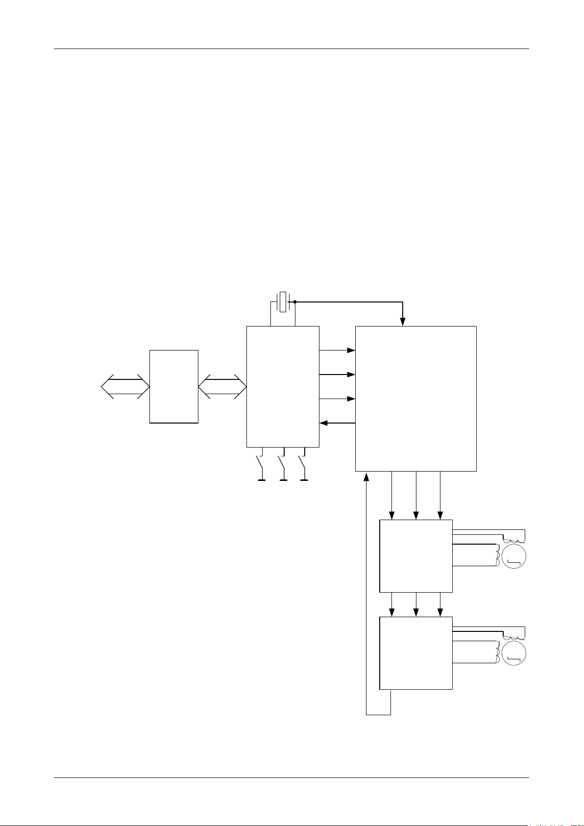
2 Introduction
The TMC429+TMC24x evaluation kit makes it possible to evaluate and to test all functions of the TMC429.
It contains the following components:
The evaluation board is equipped with the TMC429 and three stepper motor drivers
A null-modem-cable for connecting the evaluation board to the PC
On the evaluation board the Atmel ATmega8 microprocessor is used to control the TMC429. The
microprocessor’s FLASH ROM contains a program which configures the TMC429 after a reset and controls the
communication with the PC via the RS232 interface. A software running under Windows enables access to
all the registers and functions of the TMC429 from a PC. Furthermore, some simple functions can be
controlled by keys on the evaluation board.
Up to two bipolar two-phase stepper motors can be connected.
Figure 2.1: The structure of the evaluation board
Copyright © 2011, TRINAMIC Motion Control GmbH & Co. KG
Page 5

TMC429+TMC24x-EVAL Manual (V1.00 / 2011-NOV-11) 5
Order code
Description
Size of unit [mm3]
TMC429+TMC24x-EVAL
Evaluation board for TMC429, TMC246 and TMC249.
Null-modem-cable included
3 Order codes
Table 3.1: Order codes
Copyright © 2011, TRINAMIC Motion Control GmbH & Co. KG
Page 6

TMC429+TMC24x-EVAL Manual (V1.00 / 2011-NOV-11) 6
RS232
ATmega8
µC
TMC-429
Power
Connector
Function Keys
Stepper Motor Connectors
Power
LED
MAX-202
GND
+U
STOP_L STOP_R MOVE1 STOPMOVE2
uC-DIS
EXTERN
428_SPI_IN
Stop Switch
Connector
TMC246
MOTOR2
TMC249
MOTOR1
RA
RB
428_SPI_OUT
INTERN
DRIVERS
4 Quick start
For a first quick start, connect at least one stepper motor to the connectors MOTOR1 or MOTOR2 (as shown
in Figure 5.1). Please note that the stepper motors may only be connected to or disconnected from the
evaluation board while the board is disconnected from power, as otherwise the motor drivers could
get damaged!
Now, connect a power supply of 10... 28V DC and at least 1A to the power connector. The positive pole is
marked +U. When the power supply is working, the power LED will light up. Also the other two LEDs near
the buttons will flash once after powering on.
Now the following functions can be used:
The MOVE1 key: After pressing the MOVE1 key, all motors start rotating using different
accelerations and velocities and the LED near this button lights up.
The STOP key: When the STOP key is pressed once, all motors will be decelerated using different
decelerations. If this key is pressed again while the motors are being decelerated all motors will
be stopped immediately.
The MOVE2 key: The functionality of this key is similar to that of the MOVE1 key, but the motors
rotate in the opposite directions and the LED near this button lights up.
The functions MOVE1 and MOVE2 are indicated by LEDs. It is also possible to press the other MOVE key
while the motors are running. The motors will be decelerated and then accelerated in the opposite
directions.
Figure 4.1: TMC429 evaluation board overview
Copyright © 2011, TRINAMIC Motion Control GmbH & Co. KG
Page 7

TMC429+TMC24x-EVAL Manual (V1.00 / 2011-NOV-11) 7
Pin
Function
Pin
Function
1
SDO_C (TMC429)
2
uC-DISABLE
3
SDI_C (TMC429)
4
GND
5
SCS_C (TMC429)
6
GND
7
SCK_C (TMC429)
8
GND
9
+U (Motor Power)
10
+5V/+3.3V
Pin
Function
Pin
Function
1
SDO_S (TMC429)
2
uC-DISABLE
3
SDI_S (TMC429)
4
GND
5
SCS_S (TMC429)
6
GND
7
SCK_S (TMC429)
8
GND
9
+U (Motor Power)
10
+5V/+3.3V
5 Hardware
Please see also the schematics of the evaluation board (supplied as PDF files on www.trinamic.com) for a
better understanding of this description.
5.1 Connectors
The evaluation board is equipped with the following connectors:
RS232 (9-pin Sub-D plug): This is the RS232 interface for connection to a PC. The interface uses
19200 Baud, 8 data bits, no parity and one stop bit. Only the pins 2, 3 and 5 (RxD, TxD, GND) are
connected.
+U/GND: socket for power supply. The positive pole is marked +U. A diode protects the board
against wrong polarity. The voltage connected to it must not exceed 28 volts DC.
Reference switch connector: Every reference switch pin is pulled to ground by a 1k resistor. The
pin assignment of the connector is printed on the board.
MOTOR1 and MOTOR2: Stepper motor connectors. Motor #1 is driven by the TMC249 driver with
external power transistors and the other motor is driven by the TMC246 stepper motor driver.
ISP-PROG: Atmel ISP connector. This permits changing the microprocessor’s firmware using an
Atmel ISP.
Microcontroller disable jumper (uC-DIS): If this jumper is closed all functions of the
microcontroller are disabled and its SPI interface enters a high impedance state. This allows
connecting different microcontrollers to be connected to the board so that the TMC429 can also
be controlled with a different microcontroller. So for normal operation this jumper must be
open.
EXTERN/INTERN jumpers (pls. refer schematic J401, J402): Normally, these jumpers must be in the
INTERN setting (connecting the middle and the right pin). The other setting is needed to use the
428_SPI_OUT connector.
428_SPI_IN: Here, an external microcontroller can be connected to the TMC429. To use this
connector, close the microcontroller disable jumper. The pin assignment of this connector is as
follows:
Copyright © 2011, TRINAMIC Motion Control GmbH & Co. KG
428_SPI_OUT: The motor driver SPI interface of the TMC429 is connected here. So, other drivers
can be connected to the TMC429 using this connector. To make use of this feature, set the
EXTERN/INTERN jumpers to the EXTERn setting. The pin assignment of the 428_SPI_OUT
connector is as follows:
3V3: This jumper selects between 5V and 3.3V power for the microcontroller, the TMC429, the
TMC246 and the TMC249. If the jumper is open 5V will be used and if the jumper is closed 3.3V
will be used.
Page 8

TMC429+TMC24x-EVAL Manual (V1.00 / 2011-NOV-11) 8
M
OB2
OB1
OA2
OA1
5.2 Pin assignments of connectors
The pin assignment of each connector is marked on the board. Please connect the stepper motors to the
MOTOR1 and MOTOR2 connectors as shown in the drawing below (Figure 5.1).
Figure 5.1: How to connect a stepper motor
5.3 Motor drivers
The TMC429 evaluation board comes with two motor drivers: The Trinamic TMC246 and the Trinamic TMC249.
Both support 4-bit microstepping and stall detection. The difference is that the TMC249 uses external power
transistors and thus can drive motors with a coil current of more than 1.5A (on this board transistor for max
3A coil current are used).
The maximum coil current of the TMC249 can be selected using the jumpers RA and RB. It is 1.5A when they
are open and 3.0A when they are closed.
5.4 Communication with PC
The RS232 interface uses the following communication parameters: 19200 Baud, 8 data bits, no parity bit,
one stop bit. The evaluation board expects data telegrams which contain at least one command byte and,
depending on the command byte, some data bytes. Depending on the command byte, some data bytes will
be sent back as a response. There are the following command bytes (noted in hexadecimal):
$23: Send an SPI telegram to the TMC429. The evaluation board expects four data bytes which form the SPI
telegram that will be sent to the TMC429. The response from the evaluation board consists of four bytes
which contain the SPI telegram that has been sent back from the TMC429.
$45<address><data><checksum>(one byte each):Change the contents of the microprocessor’s EEPROM. The
EEPROM of the microprocessor contains 128 bytes which are copied to the configuration RAM of the TMC429
after each reset.
<Address> may be a value between 0 and 127. The following formula is used to calculate the checksum:
<Checksum>=(<Address>+<Data>) modulo 255
On success ACK ($06) will be sent back, otherwise NAK ($15) will be sent back.
$FF: The evaluation board will send a ten byte identification string, containing the firmware version number.
Data bytes are not expected by this command.
Examples:
Reading Motor #0 position register
Command from PC: $23 $03 $00 $00 $00
Response from evaluation board: $15 $00 $00 $00
Querying the identification string:
Command form PC: $FF
Response from evaluation board: EV428 V2.0
Copyright © 2011, TRINAMIC Motion Control GmbH & Co. KG
Page 9

TMC429+TMC24x-EVAL Manual (V1.00 / 2011-NOV-11) 9
6 The PC software
The PC software supplied with the TMC429 evaluation kit is a program running under Windows
95/98/NT/2000 and allows access to all the registers of the TMC429. You can install the program simply by
downloading the file EVAL429.EXE from the TRINAMIC website www.trinamic.com. After that, the software
can be run simply by double clicking the file EVAL428.EXE.
Before starting the software, the evaluation board should be connected to an RS232 interface of your PC
using the null modem cable supplied with the evaluation kit.
6.1 The Main Window
After starting the software the main window will open up (Figure 6.1). First, select the interface to which
your evaluation board is connected and click the Open button. If the connection to the evaluation board
could be established successfully, the message The board is active will be displayed. If a message like The
board does not respond is displayed, please check the power supply and the connection to your PC again
.
Now, the TMC429 status register is displayed in the TMC429 status bits section. Using the controls in the
Motor 1, Motor 2 and Motor 3 sections, the motors can be run. Just enter all necessary parameters and click
the appropriate Go! button. You can stop a motor by clicking the appropriate Stop! button. Use the buttons
All Go! and All Stop to run or stop all motors simultaneously.
Figure 6.1: The main window
Copyright © 2011, TRINAMIC Motion Control GmbH & Co. KG
Page 10

TMC429+TMC24x-EVAL Manual (V1.00 / 2011-NOV-11) 10
As the evaluation board is equipped with only two motor drivers, the Motor 3 section will have no effect
(but a third motor driver can be added to the board externally). Motor 1 is driven by the TMC249 and Motor
2 is driven by the TMC246.
First select the Ramp Mode first then fill in the other necessary parameters and last start the motor or all
motors. You will find an explanation of all parameters in the TMC429 data sheet and also in an example in
Chapter Fehler! Verweisquelle konnte nicht gefunden werden..
By clicking the TMC429 Registers button the register window opens and gives you access to every TMC429
register (Chapter 0). Click on the Graphics button to open the graphics window which displays the driving
ramps of all motors (Chapter 6.2).
6.1.1 Example
In this example it is assumed that a motor is connected to the MOTOR1 connector.
First, set the ramp mode of motor #1 to RAMP. Then enter the following parameters:
Target Position: 100000
Vmin: 1
Vmax: 500
Max Accel.: 150
Now click the appropriate Go! button. The motor will now be running until position
100000 is reached. After that, enter zero as Target Position and click the Go! button
again. The motor will run back to position zero. You can also try to change the
position on the fly, whilst the motor is running. Just enter a different position, click
the Go! button and see how the motor reacts. Also open the graphics window
(Chapter 6.2) and watch the ramps.
Now try also the other modes: The SOFTMODE is nearly similar to the RAMP mode, except that the motor
starts and stops softer. Please note, that in the RAMP and SOFTMODE modes the Vmin parameter must not
be zero because otherwise the target position sometimes cannot be reached. Hint: Some other parameters
which are not displayed in the main window are calculated and set up automatically according to the
acceleration parameter.
When using the VELOCITY mode, you can enter the acceleration and the Vmax parameter. The motor is then
accelerated to that velocity and keeps running constantly until you change the velocity and click the Go!
button again. The motor will then be accelerated or decelerated to the new velocity using the acceleration
parameter you have entered.
If you set the ramp mode to HOLD, you can only enter the Actual velocity parameter, click the Go! button
and control the velocity directly.
Please see also the files TMC429_rhz.xls and tmc429_rhzva.xls in the TMC429_Examples directory
(www.trinamic.com) for calculating the TMC429 parameters and converting them to or from physical units.
Copyright © 2011, TRINAMIC Motion Control GmbH & Co. KG
Page 11

TMC429+TMC24x-EVAL Manual (V1.00 / 2011-NOV-11) 11
6.2 The graphic display window
The graphic display window (Figure 6.2) shows the driving ramps of all the stepper motors. The following
values are displayed:
Green: the actual position of the motor
Red: the actual velocity of the motor. The value is shown as an absolute value, so negative
velocities will also be shown as positive values
Blue: the actual acceleration, also shown as an absolute value
Yellow: the actual target velocity of the motor, also displayed as an absolute value
Please note that this is only a rough and not an exact diagram.
Figure 6.2: The graphic display window
The value Time Interval shows the time between two pixels on the X axis. This value mainly depends on the
performance of the PC and will be slower when the register window is open (the display then gets slower
because more values are queried from the evaluation board). The scales of the Y axis are automatically
adapted to fit the entire curves. The curves are also displaced one pixel against each other for a better view.
If Stop when velocity = 0 is activated the display will be stopped when the velocities of all motors are zero.
All curves are cleared by clicking the Clear display button.
Copyright © 2011, TRINAMIC Motion Control GmbH & Co. KG
Page 12

TMC429+TMC24x-EVAL Manual (V1.00 / 2011-NOV-11) 12
6.3 The register window
The register window makes the direct access to all TMC429 registers possible. It contains five pages on
which all registers are displayed sorted by functional blocks. You can read more about the registers in the
TMC429 data sheet.
Figure 6.3: The register window showing the Motor 1 page
6.3.1 Motor 1, motor 2, and motor 3
On the motor pages, all registers belonging to the motors #1, #2, and #3 are displayed (Figure 6.3). In
the Actual Values and Read Only Values sections, the contents of all readable registers are displayed.
These values are updated permanently.
To change the contents of a register, first click on its name in the Registers section. Then change the
value in the appropriate edit field in the New Value section. You can also copy the actual values into
the edit fields by clicking the Copy button.
In the SPI Telegram section, the necessary SPI telegram to set the selected register to the desired
value is shown. Click the Send SPI Telegram button to send it to the evaluation board, and the value
will be set.
6.3.2 Global parameters
This page (Figure 6.4) contains all the TMC429 global parameter registers. It is made up just like the
motor register pages. The contents of the read only registers (including the reference switch flags) are
shown in the Read Only section. In the Read/Write section all writable registers are displayed. In the
Actual Values section the actual contents of the registers are shown and updated permanently. To
change a register, select it in the Registers section and fill in the new value in the New Value section.
Using the Copy button, you can copy the actual contents into the edit fields.
In the SPI Telegram section, the necessary SPI telegram to set the selected register to the desired
value is shown. Click the Send SPI Telegram button to send it to the evaluation board, and the value
will be set.
Copyright © 2011, TRINAMIC Motion Control GmbH & Co. KG
Page 13

TMC429+TMC24x-EVAL Manual (V1.00 / 2011-NOV-11) 13
Figure 6.4: The register window showing the Global Parameters page
6.3.3 RAM Table
On this page (Figure 6.5), the internal configuration RAM of the TMC429 chip (which contains the driver
configuration and the microstepping table) can be viewed and modified. Furthermore, any SPI data telegram
can be entered and sent to the evaluation board and the response can be viewed.
Figure 6.5: The register window showing the RAM Table page
Click the Read from RAM button to read the contents of the TMC429 RAM into the RAM editor. The progress
bar below the RAM editor shows the reading progress. After that, the values can be modified. By clicking the
Write to RAM button, the values will be written back to the TMC429 RAM, which is also shown by the
progress bar. Use the Save to file function to save the contents of the RAM editor to a file and the Load
from file function to read the file back into the RAM editor.
Copyright © 2011, TRINAMIC Motion Control GmbH & Co. KG
Page 14

TMC429+TMC24x-EVAL Manual (V1.00 / 2011-NOV-11) 14
The Microstep Shape function is used to calculate enhanced microstepping tables. To do this, first set the
Sigma value to the desired value (any floating point number between –1 and +1). By clicking the Calculate
button the new microstepping table will be written to the RAM editor only, and by clicking the Calculate &
Write to RAM button, the values are not only written to the RAM editor, but also to the TMC429
microstepping RAM. The driver configuration bytes will not be modified by this process.
In the SPI direct section, any SPI telegram can be entered and sent to the TMC429 by clicking the Send
button. The response sent from the TMC429 is then displayed below the Send button.
6.4 The stallGuard™ window
Clicking the TMC24x StallGuard button opens the StallGuard window (Figure 6.6). Here the StallGuard
features of the TMC246 and the TMC249 can be explored.
Figure 6.6: The StallGuard window
For each of the motor driver chips the evaluation board is equipped with the error flags are shown
by the blue LEDs and the load value is shown by the red bar in the Stall Detection. A stall detection
threshold can be set with the slider beside the red bar. If the load value shown by the bar reaches
the stall detection theshold the motor will be stopped immediately (this is done by the
microcontroller firmware of the evaluation board that gets is parameters via the RS232 interface).
The abbreviations at the error flag LEDs have the following meanings:
OC-A: Overcurrent on phase A.
OC-A: Overcurrent on phase B.
OL-A: Open load on phase A.
OL-B: Open load on phase B.
OC-HS: Overcurrent on high side.
UV: Undervoltage.
OT-PW: Overtemperature pre-warning.
OT: Overtemperature.
Copyright © 2011, TRINAMIC Motion Control GmbH & Co. KG
Page 15

TMC429+TMC24x-EVAL Manual (V1.00 / 2011-NOV-11) 15
6.5 Calc429 program
The software CD also contains the program Calc428. This program serves as a help to calculate the PMul and
PDiv parameters (see the TMC429 datasheet for an exact explanation of these parameters). It can be run
simply by double clicking the file CALC429.EXE.
Figure 6.7: Calc429 program
First, enter the parameters on the left side. After that, click the Calculate button and the values will be
calculated and displayed on the right side of the window.
6.6 Eval429EEP program
Using the program Eval429EEP, you can modify the contents of the EEPROM of the microprocessor on the
evaluation board via the RS232 interface. The contents of the EEPROM are copied to the TMC429 RAM after
each reset. So, for example, a modified microstepping table could be stored in the EEPROM and will be
present immediately after powering on the evaluation board. To do this, you will first have to edit the RAM
contents using the RAM editor (see Chapter 6.3.3) and store it in a file. The contents of such a file can then
be stored in the EEPROM using the Eval429EEP program.
Start the program by double clicking the EVAL428EEP.EXE file.
Figure 6.8: Eval428EEP program
Then select the interface your evaluation board is connected to and make sure that it is connected and
powered on. Now select your RAM file either by entering its path directly or by clicking the Browse button
and selecting a file in the file selection dialogue. Last, click the Start button. After a confirmation, the
programming process starts. This is also shown by the progress bar. At the end of the programming
process, a message dialogue shows if the programming process has been successful.
Copyright © 2011, TRINAMIC Motion Control GmbH & Co. KG
Page 16

TMC429+TMC24x-EVAL Manual (V1.00 / 2011-NOV-11) 16
7 The stallGuard™ profiler
The stallGuard™ profiler is a utility that helps you to find the best parameters for using stall detection. It
can be used together with the TMC429 evaluation board.
7.1 Installation
The file StallProfiler429.exe is available on www.trinamic.com. To start it, just double click the file. There is
no special installation procedure needed. The program can only be used together with the TMC429+TMC24xEVAL V1.0 or higher.
7.2 Usage
After starting the program its window appears. First make sure that your evaluation board is connected to
the PC and supplied with power. It is not possible to change parameters of the TMC429 using this program.
Do this by using the Eval429 program before using this one (do not power off the evaluation board after
that). Then select the COM port to which the evaluation is connected and click the Open button. Now the
connection to the evaluation board will be established.
Figure 7.1: The StallGuard profiler window
To record a stallGuard™ profile, first fill in the necessary parameters:
Motor driver: Select the motor driver on the evaluation board which you would like to use. As the
evaluation board is equipped with a TMC246 and a TMC249, it can either be TMC246 or TMC249. Make
sure that your motor is connected to the driver you would like to use.
Start velocity: This is the velocity value that is used at the beginning of the profile recording.
End velocity: The profile recording stops when this velocity value has been reached. Start velocity and
end velocity must not be equal. The range for each of the values is -2047… +2047.
Pulse_Div: This is the pulse divisor of the TMC429 that is a pre-divider that selects the velocity range
(see the TMC429 data sheet for explanation). It is set to 5 when the evaluation board is switched on, but
it can be set to meet your needs here.
Microsteps: The number of microsteps to be used can also be set here. The default value on the
evaluation board is 16.
After all these parameters have been set, click on the start button to start the stallGuard™ profile recording.
Depending on the range between start and end velocity this can take several minutes, as the load value for
every velocity value is measured ten times. The Actual velocity value shows the velocity that is currently
being tested and so tells you the progress of the profile recording. You can also abort a profile recording by
clicking the Abort button.
Copyright © 2011, TRINAMIC Motion Control GmbH & Co. KG
Page 17

TMC429+TMC24x-EVAL Manual (V1.00 / 2011-NOV-11) 17
7.3 The result
The result is shown as a graphic at the right side of the program window. After the profile recording has
finished you can scroll through the profile graphic using the scroll bar below it. The scale on the vertical
axis shows the load value: a higher value means a higher load. The scale on the horizontal axis is the
velocity scale. The color of each line shows the standard deviation of the ten load values that have been
measured for the velocity at that point. This is an indicator for the vibration of the motor at the given
velocity.
There are three colors used:
Green: The standard deviation is very low or zero. This means that there is effectively no vibration at
this velocity.
Yellow: This color means that there might be some low vibration at this velocity.
Red: The red color means that there is high vibration at that velocity.
Figure 7.2: A stallGuard™ profile
The data can also be exported as a text file or to Microsoft Excel. To do this, click the Export button and a
pop-up menu with the following choices appears:
Text file: This function lets you choose a text file to which the data will be saved.
Excel: This function exports the data to Microsoft Excel. It must be installed on your PC to make use of
this function, as Excel is now started (if not already running) and the data is directly sent to Excel and
not written into a file. Of course you can then save the data by using the Save function in Excel. Please
note that it takes some time to transfer the data to Excel.
A profile that has been saved to a text file can be reloaded: just click the Load button and you can select a
file. The contents of the file will be shown as a graphical profile.
7.4 Interpreting the result
In order to make effective use of the stallGuard™ feature you should choose a velocity where the load
value is as low as possible and where the color is green. The very best velocity values are those where the
load value is zero (areas that do not show any green, yellow or red line). Velocities shown in yellow can
also be used, but with care as they might cause problems (maybe the motor stops even if it is not stalled).
Velocities shown in red should not be chosen. Because of vibration the load value is often unpredictable
and so not usable to produce good results when using stall detection.
As it is very seldom that exactly the same result is produced when recording a profile with the same
parameters a second time, always two or more profiles should be recorded and compared against each
other.
Copyright © 2011, TRINAMIC Motion Control GmbH & Co. KG
Page 18

TMC429+TMC24x-EVAL Manual (V1.00 / 2011-NOV-11) 18
Version
Date
LL – Lars Larsson
OK- Olav Kahlbaum
SD – Sonja Dwersteg
Author
Description
1.00
2011-NOV-11
SD
Initial version, based on TMC428 Eval Kit 3.0 Manual
(writers: LL, OK)
8 Revision history
8.1 Document revision
Copyright © 2011, TRINAMIC Motion Control GmbH & Co. KG
 Loading...