

Page 1

Evaluation Board for Stepper
EVALUATION BOARD
TMC2300-EVAL Evaluation Board
Document Revision V1.0 • 2019-SEP-02
The TMC2300-EVAL allows evaluation of the TMC2300 in combination with the TRINAMIC evaluation
board system, or as stand-alone-board. It uses the standard schematic and offers several options
in order to test different modes of operation.
Features
• 2-phase stepper motor up to 1.2A
coil current (2A peak)
• Supply Voltage 2. . .11V DC
• Standby < 50nA typical current draw
• UART for advanced configuration op-
tions
• 1...256 microsteps
• Step/Dir interface
• StealthChop2™ silent motor oper-
ation
• Stall detection StallGuard4™ in StealthChop mode
Applications
• IoT & Handheld devices
• Battery operated equipment
• Printers, POS
Simplified Block Diagram
• Miniature 3D Printers
• Toys
• Office and home automation
• CCTV, Security
• HVAC
• Mobile medical devices
©2019 TRINAMIC Motion Control GmbH & Co. KG, Hamburg, Germany
Terms of delivery and rights to technical change reserved.
Download newest version at: www.trinamic.com
Read entire documentation.
Page 2

TMC2300-EVAL Evaluation Board • Document Revision V1.0 • 2019-SEP-02
2 / 11
Contents
1 Getting Started 3
1.1 First Start-Up . . . . . . . . . . . . . . . . . . . . . . . . . . . . . . . . . . . . . . . . . . . . . . . . . 4
2 Hardware Information 5
2.1 Onboard Jumpers . . . . . . . . . . . . . . . . . . . . . . . . . . . . . . . . . . . . . . . . . . . . . . 5
3 Evaluation Features in the TMCL-IDE 6
3.1 Velocity Mode . . . . . . . . . . . . . . . . . . . . . . . . . . . . . . . . . . . . . . . . . . . . . . . . 6
3.2 Position Mode . . . . . . . . . . . . . . . . . . . . . . . . . . . . . . . . . . . . . . . . . . . . . . . . 7
3.3 ChipClick . . . . . . . . . . . . . . . . . . . . . . . . . . . . . . . . . . . . . . . . . . . . . . . . . . . 8
3.4 CoolStep™ Tuning . . . . . . . . . . . . . . . . . . . . . . . . . . . . . . . . . . . . . . . . . . . . . . 9
4 Revision History 11
4.1 Document Revision . . . . . . . . . . . . . . . . . . . . . . . . . . . . . . . . . . . . . . . . . . . . . 11
©2019 TRINAMIC Motion Control GmbH & Co. KG, Hamburg, Germany
Terms of delivery and rights to technical change reserved.
Download newest version at www.trinamic.com
Page 3

TMC2300-EVAL Evaluation Board • Document Revision V1.0 • 2019-SEP-02
1 Getting Started
3 / 11
You need
• TMC2300-EVAL
• Landungsbruecke with latest firmware. (The
Startrampe does not support the UART interface.)
• Eselsbruecke bridge board
• Stepper motor (e.g. QMot line)
• USB interface
• Power Supply
• Latest TMCL-IDE V3.0 and PC
• Cables for interface, motors and power
Precautions
• Do not mix up connections or short-circuit pins.
• Avoid bundling I/O wires with motor wires.
• Do not exceed the maximum rated supply volt-
age!
• Do not connect or disconnect the motor while
powered!
• START WITH POWER SUPPLY OFF!
Figure 1: Getting started
©2019 TRINAMIC Motion Control GmbH & Co. KG, Hamburg, Germany
Terms of delivery and rights to technical change reserved.
Download newest version at www.trinamic.com
Page 4

TMC2300-EVAL Evaluation Board • Document Revision V1.0 • 2019-SEP-02
1.1 First Start-Up
1. Make sure that the latest version of the TMCL-IDE 3.0 is installed. The TMCL-IDE can be downloaded
from www.trinamic.com/support/software/tmcl-ide/.
2. Open the TMCL-IDE and connect the Landungsbruecke via USB to the computer. For Windows 8 and
higher is no driver needed, on Windows 7 machines the TMCL-IDE is installing the driver automatically.
3. Verify that the Landungsbruecke is using the latest firmware version. The firmware version is shown
in the connected device tree.
4 / 11
Figure 2: Firmware Version
4. The TMCL-IDE 3.0 needs room to show all important information and to provide a good overview.
Therefore, arrange the main window related to your needs. We recommend using full screen. For
evaluation boards it is essential to have access to the registers. Therefore open up the Register
Browser (left side). For a better view click top right on the normal icon to get a maximized register
browser window.
5. The TMCL-IDE includes a dialogue for diagnostic tasks. Further, the dialogue provides an overview of
the connected motion controller and driver chips. A window pops up immediately after connecting
the evaluation kit the first time. The window shows the actual status of the connections. The second
tab of the dialogue offers the possibility to choose basic settings or to reset the module to factory
defaults.
Figure 3: Landungsbruecke Dialogue
©2019 TRINAMIC Motion Control GmbH & Co. KG, Hamburg, Germany
Terms of delivery and rights to technical change reserved.
Download newest version at www.trinamic.com
Page 5

TMC2300-EVAL Evaluation Board • Document Revision V1.0 • 2019-SEP-02
5 / 11
2 Hardware Information
All design files for our evaluation boards are available for free. We offer the original ECAD files (Eagle,
Altium, or PADS), Gerber data, the BOM, and PDF copies. Please check schematics for Jumper settings
and input/output connector description.
The files can be downloaded from the evaluation boards’ website directly at out homepage: TRINAMIC
Eval Kit homepage.
Note
If files are missing on the website or something is wrong please send us a note.
2.1 Onboard Jumpers
The TMC2300-Eval board has two jumpers on the top left side to select the Step/Direction source. The
internal source uses the MCU to generate steps, the external source uses the external Step/Direction pin
header in the lower right corner.
©2019 TRINAMIC Motion Control GmbH & Co. KG, Hamburg, Germany
Terms of delivery and rights to technical change reserved.
Download newest version at www.trinamic.com
Page 6

TMC2300-EVAL Evaluation Board • Document Revision V1.0 • 2019-SEP-02
6 / 11
3 Evaluation Features in the TMCL-IDE
This chapter gives some hints and tips on using the functionality of the TMCL-IDE, e.g. how to use the
velocity mode or using the wizards.
Note
In order to achieve good settings please refer to descriptions and flowcharts
in the TMC2300-LA datasheet. The register browser of the TMCL-IDE provides
helpful information about any currently selected parameter. Beyond that, the
datasheet explains concepts and ideas which are essential for understanding
how the registers are linked together and which setting will fit for which kind
of application. For getting more familiar with the evaluation kit in the beginning
of your examinations, drive the motor using velocity mode and/or positioning
mode first. Beyond this, the direct mode function can be used. This way, TMCL
commands can be sent to the evaluation board system.
3.1 Velocity Mode
To move the motor in velocity mode, open the velocity mode tool by clicking the appropriate entry in the
tool tree. In the velocity mode tool you can enter the desired velocity and acceleration and then move the
motor using the arrow buttons. The motor can be stopped at any time by clicking the stop button. Open
the velocity graph tool to get a graphical view of the actual velocity.
Note
In order to get a more accurate graphical velocity view, close the register browser
window when using the velocity graph.
Figure 4: Driving the motor in velocity mode (TMCL-IDE provides similar view for TMC2300-EVAL)
©2019 TRINAMIC Motion Control GmbH & Co. KG, Hamburg, Germany
Terms of delivery and rights to technical change reserved.
Download newest version at www.trinamic.com
Page 7

TMC2300-EVAL Evaluation Board • Document Revision V1.0 • 2019-SEP-02
7 / 11
3.2 Position Mode
To move the motor in position mode, open the position mode tool by clicking the appropriate entry in the
tool tree. In the position mode tool you can enter a target position and then start positioning by clicking
the Absolute or Relative Move button. The speed and acceleration used for positioning can also be adjusted here.
Open the position graph tool to get a graphical view of the actual position.
Note
In order to get a more accurate graphical position view, close the register browser
window when using the position graph.
Figure 5: Driving the motor in position mode (TMCL-IDE provides similar view for TMC2300-EVAL)
©2019 TRINAMIC Motion Control GmbH & Co. KG, Hamburg, Germany
Terms of delivery and rights to technical change reserved.
Download newest version at www.trinamic.com
Page 8
TMC2300-EVAL Evaluation Board • Document Revision V1.0 • 2019-SEP-02
8 / 11
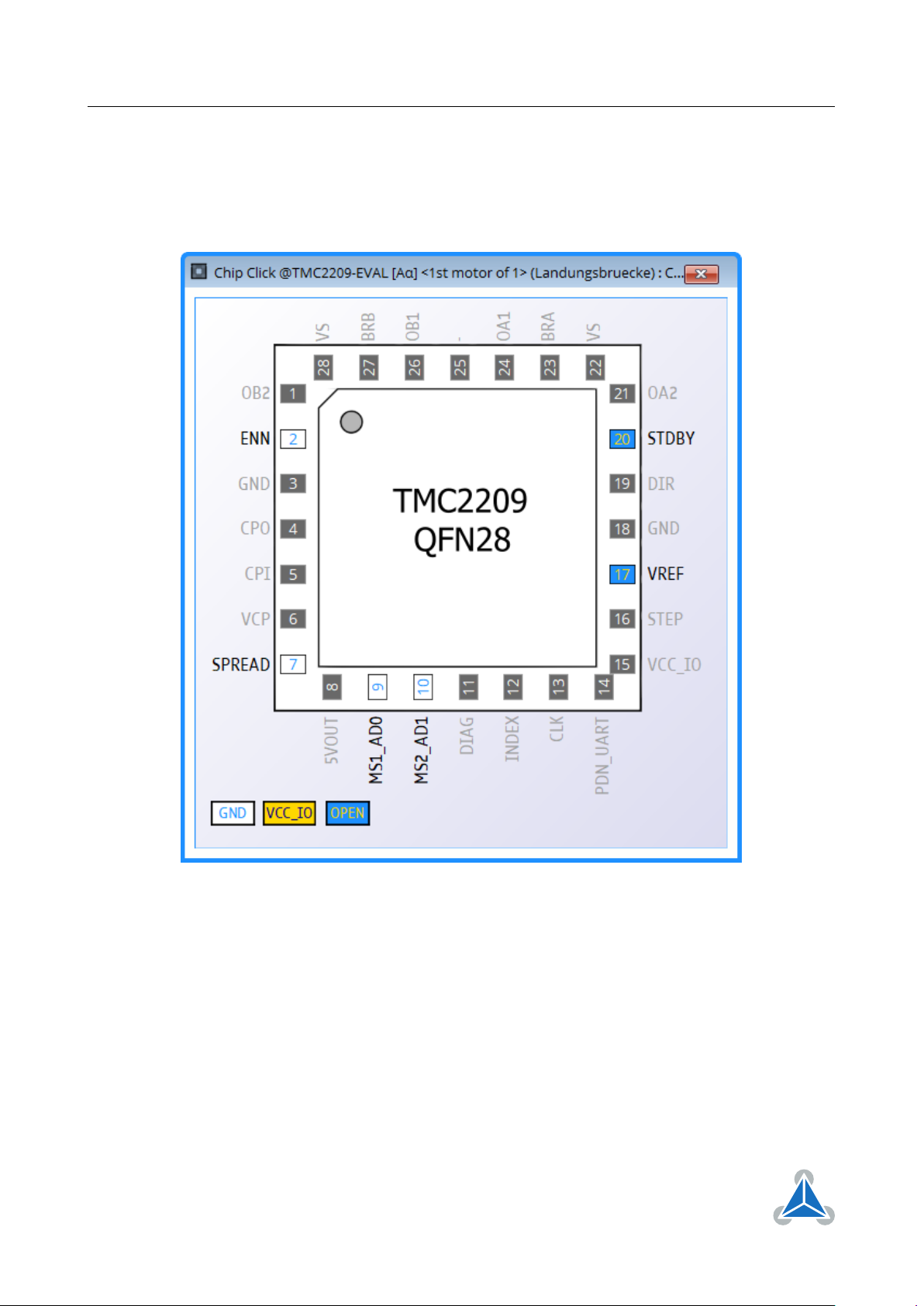
3.3 ChipClick
To configure the control pins for the TMC2300-EVAL, open the ChipClick tool by clicking the appropriate
entry in the tool tree. To view a description of a pins possible configurations, hover the mouse over the
pin in the graphical view. To change the pins state, click on it.
Figure 6: Configuring the control pins of a TMC2209 (similar for other ICs).
©2019 TRINAMIC Motion Control GmbH & Co. KG, Hamburg, Germany
Terms of delivery and rights to technical change reserved.
Download newest version at www.trinamic.com
Page 9
TMC2300-EVAL Evaluation Board • Document Revision V1.0 • 2019-SEP-02
9 / 11
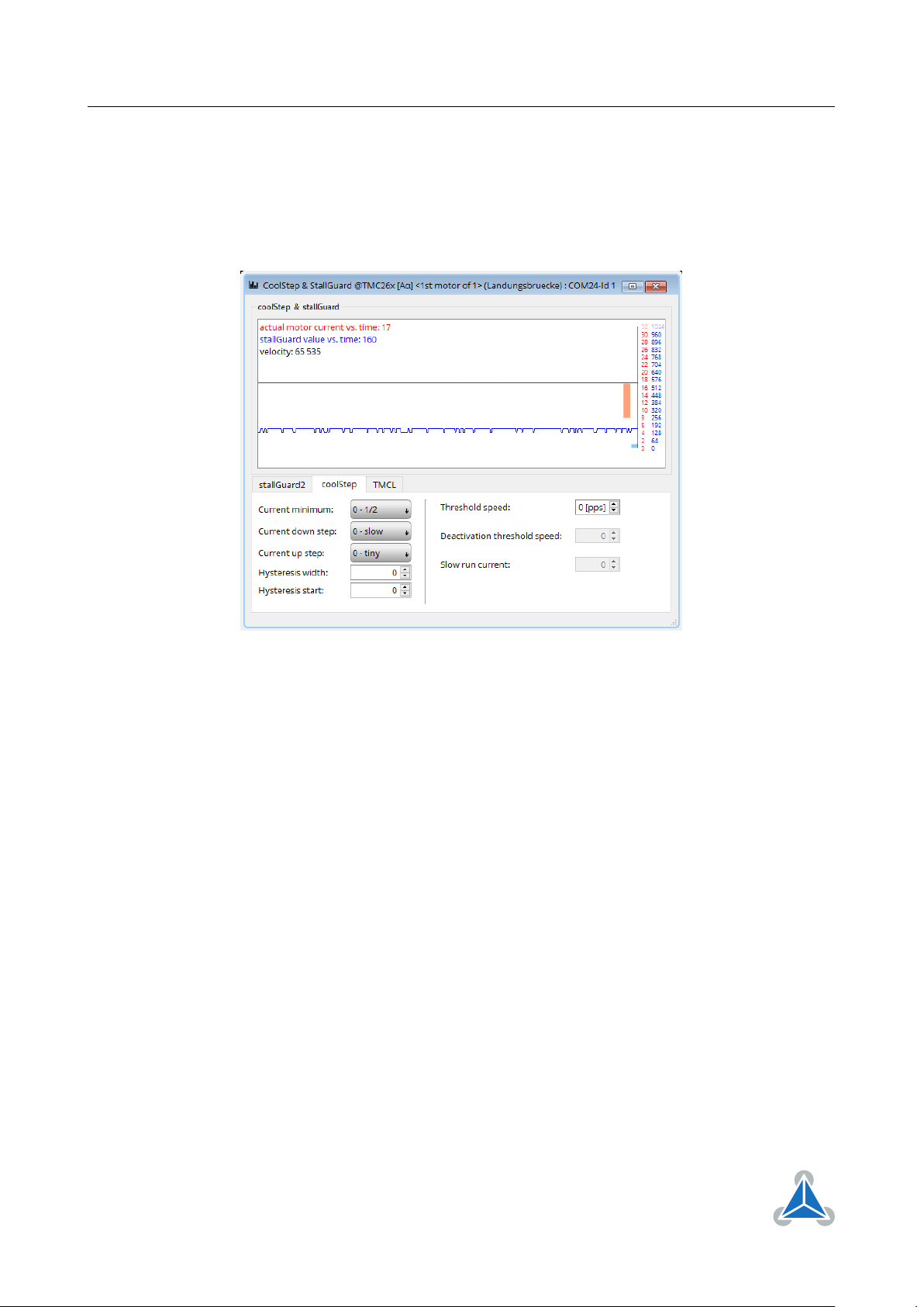
3.4 CoolStep™ Tuning
With the TMCL IDE and the EVAL-KIT you have a powerful tool to find your CoolStep™ to run your motor
most energy efficient and cool. To tune it, please open the CoolStep™ & StallGuard2™ window you’ll find
on the left of the IDE when you have connected the EVAL board. On the CoolStep™ tab you will see below
picture by default.
Figure 7: TMCL IDE v3.0.20.0 Parameter calculator
CoolStep™ will get activated as soon as you change the "Hysteresis start" value higher than 0 and enter a
"Threshold speed" value higher than 0.
©2019 TRINAMIC Motion Control GmbH & Co. KG, Hamburg, Germany
Terms of delivery and rights to technical change reserved.
Download newest version at www.trinamic.com
Page 10
TMC2300-EVAL Evaluation Board • Document Revision V1.0 • 2019-SEP-02
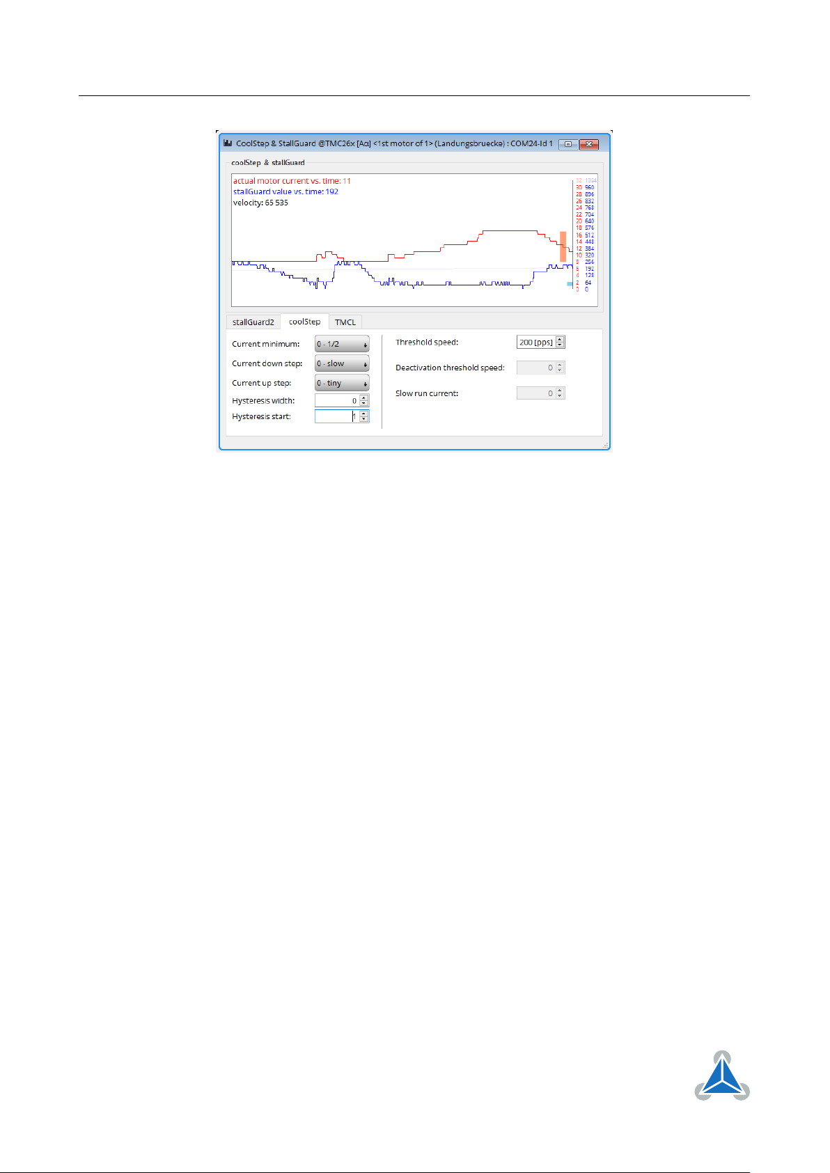
Figure 8: CoolStep™ & StallGuard2™ window
10 / 11
The above values activate CoolStep™ but the values can be fine tuned to make CoolStep™ work reliable
and in a way as you need it in your application. For that it is important to understand what each setting
is doing.
• Current minimum: The current minimum setting will be the lowest current when CoolStep™ is
activated. With 1A RMS the current will either be reduced to a quarter or to the half of this current
when no or less force is applied to the motor shaft.
• Current down step: Current down steps defines the speed of the current to drop down after load
gets released from the motor shaft.
• Current up step: This setting defines the step height when hitting the lower StallGuard2™ threshold
(Hysteresis start).
• Hysteresis width: This setting defines the area of the StallGuard2™ threshold (Hysteresis end).
• Hysteresis start: This setting defines the switching point, related to the StallGuard2™ value, to
boost up the current by one step.
©2019 TRINAMIC Motion Control GmbH & Co. KG, Hamburg, Germany
Terms of delivery and rights to technical change reserved.
Download newest version at www.trinamic.com
Page 11

TMC2300-EVAL Evaluation Board • Document Revision V1.0 • 2019-SEP-02
11 / 11
4 Revision History
4.1 Document Revision
Version Date Author Description
1.0 2019-SEP-02 LH Initial release.
1.1 2019-NOV-05 LH Updated short specification list and reworded onboard jumper description
Table 1: Document Revision
©2019 TRINAMIC Motion Control GmbH & Co. KG, Hamburg, Germany
Terms of delivery and rights to technical change reserved.
Download newest version at www.trinamic.com
 Loading...