

Page 1

TMC211 DATASHEET (V. 1.04 / January 7, 2005) 1
TMC211 – DATASHEET
Micro Stepping Stepper Motor
Controller / Driver with LIN Interface
TRINAMIC
®
Motion Control GmbH & Co. KG
Sternstraße 67
D – 20357 Hamburg
GERMANY
P +49 - (0) 40 - 51 48 06 - 0
F +49 - (0) 40 - 51 48 06 - 60
www.trinamic.com
info@trinamic.com
19
18
17
16
15
14
13
20
SWI
VBAT
OA1
GND
OB1
OA2
GND
12
OB2
VBAT
TMC211
SOIC-20
HW01
VDD3GND4TST5LIN6GND
HW1
2
HW2
CPN
7
8
9
11
VCP
CPP
10
1 Features
The TMC211 is a combined micro-stepping stepper motor motion controller and driver with RAM and
OTP memory. The RAM or OTP memory is used to store motor parameters and configuration settings.
The TMC211 allows up to four bit of microstepping and a coil current of up to 800 mA. After
initialization it performs all time critical tasks autonomously based on target positions and velocity
parameters. Communications to a host takes place via LIN. Together with an inexpensive
microcontroller the TMC211 forms a complete motion control system. The main benefits of the
TMC211 are:
• Motor driver
• Controls one stepper motor with four bit microstepping
• Programmable Coil current up to 800 mA
• Supply voltage operating range 8V ... 29V
• Fixed frequency PWM current control with automatic selection of fast and slow decay mode
• Full step frequencies up to 1 kHz
• High temperature, open circuit, short, over-current and under-voltage diagnostics
• Motion controller
• Internal 16-bit wide position counter
• Configurable speed and acceleration settings
• Build-in ramp generator for autonomous positioning and speed control
• On-the-fly alteration of target position
• reference switch input available for read out
• LIN interface
• Physical and Data-Link Layers conform to LIN specification rev. 1.3
• Field-programmable node addresses (128)
• Dynamically allocated identifiers
• Diagnostics and status information as well as motion parameters accessable
• LIN bus short-circuit protection to supply and ground
• Lost LIN safe operation
Copyright © 2004-2005 TRINAMIC Motion Control GmbH & Co. KG
Page 2

2 TMC211 DATASHEET (V. 1.04 / January 7, 2005)
Life support policy
TRINAMIC Motion Control GmbH & Co. KG does
not authorize or warrant any of its products for
use in life support systems, without the specific
written consent of TRINAMIC Motion Control
GmbH & Co. KG.
Life support systems are equipment intended to
support or sustain life, and whose failure to
perform, when properly used in accordance with
instructions provided, can be reasonably
expected to result in personal injury or death.
© TRINAMIC Motion Control GmbH & Co. KG 2005
Information given in this data sheet is believed to
be accurate and reliable. However no
responsibility is assumed for the consequences
of its use nor for any infringement of patents or
other rights of third parties which may result form
its use.
Specifications subject to change without notice.
Copyright © 2004-2005 TRINAMIC Motion Control GmbH & Co. KG
Page 3

TMC211 DATASHEET (V. 1.04 / January 7, 2005) 3
Table of Contents
1 FEATURES .....................................................................................................................................1
2 GENERAL DESCRIPTION .............................................................................................................5
2.1 BLOCK DIAGRAMM......................................................................................................................5
2.2 POSITION CONTROLLER / MAIN CONTROL ...................................................................................5
2.3 STEPPER MOTOR DRIVER...........................................................................................................5
2.4 LIN INTERFACE ..........................................................................................................................6
2.5 MISCELLANEOUS ........................................................................................................................6
2.6 PIN AND SIGNAL DESCRIPTIONS..................................................................................................6
3 TYPICAL APPLICATION................................................................................................................7
4 ORDERING INFORMATION ..........................................................................................................7
5 FUNCTIONAL DESCRIPTION .......................................................................................................8
5.1 POSITION CONTROLLER AND MAIN CONTROLLER.........................................................................8
5.1.1 Stepping Modes ................................................................................................................ 8
5.1.2 Velocity Ramp...................................................................................................................8
5.1.3 Examples for different Velocity Ramps.............................................................................9
5.1.4 Vmax Parameter .............................................................................................................10
5.1.5 Vmin Parameter ..............................................................................................................11
5.1.6 Acceleration Parameter ..................................................................................................11
5.1.7 Position Ranges..............................................................................................................12
5.1.8 Secure Position...............................................................................................................12
5.1.9 External Switch ...............................................................................................................12
5.1.10 Motor Shutdown Management........................................................................................ 13
5.1.11 Reference Search / Position initialization........................................................................14
5.1.12 Sleep Mode.....................................................................................................................14
5.1.13 Temperature Management .............................................................................................15
5.1.14 Battery Voltage Management .........................................................................................16
5.1.15 Internal handling of commands and flags .......................................................................17
5.2 RAM AND OTP MEMORY .........................................................................................................19
5.2.1 RAM Registers................................................................................................................ 19
5.2.2 Status Flags ....................................................................................................................20
5.2.3 OTP Memory Structure...................................................................................................21
5.3 STEPPER MOTOR DRIVER.........................................................................................................21
5.3.1 Coil current shapes .........................................................................................................22
5.3.2 Transition Irun to Ihold ....................................................................................................23
5.3.3 Chopper Mechanism....................................................................................................... 24
6 LIN INTERFACE...........................................................................................................................25
6.1 GENERAL DESCRIPTION ...........................................................................................................25
6.2 PHYSICAL LAYER......................................................................................................................25
6.3 ANALOG PART..........................................................................................................................26
6.4 SLAVE OPERATIONAL RANGE FOR PROPER SELF SYNCHRONIZATION ...........................................26
6.5 PHYSICAL ADDRESS OF THE CIRCUIT .........................................................................................27
6.6 ELECTRO MAGNETIC COMPABILITY ...........................................................................................27
6.7 ERROR STATUS REGISTER .......................................................................................................27
6.8 DYNAMIC ASSIGNMENT OF LIN IDENTIFIERS ..............................................................................28
6.9 LIN MESSAGE FRAMES ............................................................................................................29
6.9.1 Writing Frames ...............................................................................................................29
6.9.2 Writing Frame Type#1 (2 or 4 bytes)..............................................................................30
6.9.3 Writing Frame Type#2 (2, 4 or 8 bytes)..........................................................................30
6.9.4 Writing Frame Type#3 (2 bytes) .....................................................................................30
6.9.5 Writing Frame Type#4 (8 bytes) .....................................................................................30
Copyright © 2004-2005 TRINAMIC Motion Control GmbH & Co. KG
Page 4

4 TMC211 DATASHEET (V. 1.04 / January 7, 2005)
6.9.6 Reading Frames ............................................................................................................ 31
6.9.7 Reading Frame Type#5 (2, 4 or 8 bytes) ....................................................................... 31
6.9.8 Reading Frame Type#6 (8 bytes) .................................................................................. 31
6.9.9 Reading Frame Type#7 (Preparing frame) .................................................................... 32
6.9.10 Reading Frame Type#8 (Preparing frame) .................................................................... 32
6.10 APPLICATION COMMANDS OVERVIEW ................................................................................... 33
6.11 COMMAND DESCRIPTION...................................................................................................... 34
6.11.1 GetActualPos ................................................................................................................. 34
6.11.2 GetFullStatus ................................................................................................................. 36
6.11.3 GetOTPParam ............................................................................................................... 38
6.11.4 GetStatus .......................................................................................................................39
6.11.5 GotoSecurePosition ....................................................................................................... 39
6.11.6 HardStop ........................................................................................................................39
6.11.7 ResetPosition ................................................................................................................. 40
6.11.8 ResetToDefault .............................................................................................................. 40
6.11.9 RunInit............................................................................................................................ 41
6.11.10 SetMotorParam .......................................................................................................... 42
6.11.11 SetOTPParam ............................................................................................................ 42
6.11.12 SetPosition ................................................................................................................. 43
6.11.13 SetPositionShort......................................................................................................... 44
6.11.14 SoftStop...................................................................................................................... 45
6.11.15 Sleep Mode ................................................................................................................ 45
6.12 POSITIONING TASK EXAMPLE ............................................................................................... 46
7 FREQUENTLY ASKED QUESTIONS ......................................................................................... 48
7.1 USING THE BUS INTERFACE...................................................................................................... 48
7.2 GENERAL PROBLEMS WHEN GETTING STARTED......................................................................... 48
7.3 USING THE DEVICE .................................................................................................................. 49
7.4 FINDING THE REFERENCE POSITION .......................................................................................... 50
8 PACKAGE OUTLINE ................................................................................................................... 51
8.1 SOIC-20 ................................................................................................................................ 51
9 PACKAGE THERMAL RESISTANCE AND LAYOUT CONSIDERATIONS ............................... 52
9.1 SOIC-20 PACKAGE ................................................................................................................. 52
10 ELECTRICAL CHARACTERISTICS ........................................................................................ 53
10.1 ABSOLUTE MAXIMUM RATINGS ............................................................................................. 53
10.2 OPERATING RANGES ........................................................................................................... 53
10.3 DC PARAMETERS ................................................................................................................ 53
10.4 AC PARAMETERS ................................................................................................................ 55
11 REVISION HISTORY................................................................................................................56
Copyright © 2004-2005 TRINAMIC Motion Control GmbH & Co. KG
Page 5

TMC211 DATASHEET (V. 1.04 / January 7, 2005) 5
2 General Description
2.1 Block Diagramm
SWI
PWM
regulator
X
PWM
regulator
Y
Reference voltage
&
Thermal monitoring
LIN
HW0
HW1
HW2
TST
VBAT
VDD
LIN
transceiver
LIN
slave
controller
Sy nchro nous
I/O controller
(test)
Voltage
regulator
Position controller
Main control
Registers
&
OTP + ROM
Oscillator
Decoder
Sinewave
table
DACs
Charge pump
VCP CP2 CP1
2.2 Position Controller / Main Control
Motor parameters, e.g. acceleration, velocity and position parameters are passed to the main control
block via the LIN interface. These information are stored internally in RAM or OTP memory and are
accessable by the position controller. This block takes over all time critical tasks to drive a stepper
motor to the desired position under abiding the desired motion parameters.
The main controller gets feedback from the stepper motor driver block and is able to arrange internal
actions in case of possible problems. Diagnostics information about problems and errors are
transferred to the LIN interface block.
2.3 Stepper Motor Driver
Two H-bridges are employed to drive both windings of a bipolar stepper motor. The internal transistors
can reach an output current of up to 800 mA. The PWM principle is used to force the given current
through the coils. The regulation loop performs a comparison between the sensed output current and
the internal reference. The PW M signals to drive the power transistors are derived from the output of
the current comparator.
OA1
OA2
OB1
OB2
Copyright © 2004-2005 TRINAMIC Motion Control GmbH & Co. KG
Page 6

6 TMC211 DATASHEET (V. 1.04 / January 7, 2005)
2.4 LIN Interface
Communication between a host and the TMC211 takes places via the bi-directional LIN interface.
Motion Instructions and diagnostic information are provided to or from the Main Control block. It is
possible to connect up to 128 devices on the same bus. Slave addresses are programmable via OTP
memory or external pins. The LIN interface implements the MAC and LLC layers according to the OSI
reference model.
2.5 Miscellaneous
Besides the main blocks the TMC211 contains the following:
• an internal charge pump is used to drive the high side transistors.
• an internal oscillator running at 4 MHz +/- 10% to clock the LIN protocol handler, the positioning
unit, and the main control block
• internal voltage reference for precise referencing
• a 5 Volts voltage regulator to supply the digital logic
• protection block featuring Thermal Shutdown, Power-On-Reset, etc.
2.6 Pin and Signal Descriptions
Pin SOIC20 Description
HW0 1 hard-wired LIN address bit #0 input
HW1 2 hard-wired LIN address bit #1 input
VDD 3 Internal supply (needs external decoupling capacitor)
GND 4,7,14,17 ground, heat sink
TST 5 test pin (to be tied to ground in normal operation)
LIN 6 LIN-bus connection
HW2 8 hard-wired LIN address bit #2 input
CPN 9 negative connection of external charge pump capacitor
CPP 10 positive connection of external charge pump capacitor
VCP 11 connection of external charge pump filter capacitor
VBAT 12,19 battery voltage supply
OB2 13 negative end of phase B coil
OB1 15 positive end of phase B coil
OA2 16 negative end of phase A coil
OA1 18 positive end of phase A coil
SWI 20 reference switch input
HW0
HW1
VDD
GND
TST
LIN
GND
HW2
CPN
CPP
1
2
3
4
5
6
7
8
9
10
TMC211
20
SWI
19
VBAT
18
OA1
17
GND
16
OA2
15
OB1
14
GND
13
OB2
12
TRINA M IC
VBAT
11
VCP
Table 1: TMC211 Signal Description
Copyright © 2004-2005 TRINAMIC Motion Control GmbH & Co. KG
Page 7

TMC211 DATASHEET (V. 1.04 / January 7, 2005) 7
3 Typical Application
Connect to GND or
+5V (VDD, Pin 3)
Connect to GND or
+5V (VDD, Pin 3)
100 nF
1 µF
Tantalum
HW0 SWI
1 20
HW1
2
VDD
3
GND
4
VBAT
OA1
GND
Ω
/1/4W
1k
19
18
17
100 nF
SWI
2.7 nF
Connect to
GND or V
BAT
M
OA2
OB1
GND
OB2
VBAT
VCP
16
15
14
13
12
11
Connect to
GND or V
BAT
2.7 nF
LIN Bus
VDR 27V
1kΩ /1/4W
220 nF
16 V
TST
5
LIN
6
GND
7
HW2
8
CPN
9
CPP
10
Figure 1: TMC211 Typical Application
Notes :
• Resistors tolerance +- 5%
• 2.7nF capacitors: 2.7nF is the minimum value, 10nF is the maximum value
• the 1µF and 100µF must have a low ESR value
• 100nF capacitors must be close to pins V
and VDD
BB
• 220nF capacitors must be as close as possible to pins CPN, CPP, V
100 nF
220 nF
16 V
and VBB to reduce EMC radiation.
CP
100 µF
V
BAT
8...29 V
4 Ordering Information
Part No. Package Peak Current Temperature Range
TMC211-PA20
(pre-series marking,
same IC as TMC211-SA)
TMC211-SA SOIC-20 800mA -40°C..125°C
Copyright © 2004-2005 TRINAMIC Motion Control GmbH & Co. KG
SOIC-20 800 mA -40°C..125°C
Table 2: Ordering Information
Page 8

8 TMC211 DATASHEET (V. 1.04 / January 7, 2005)
5 Functional Description
5.1 Position Controller and Main Controller
5.1.1 Stepping Modes
The TMC211 supports up to 16 micro steps per full step, which leads to smooth and low torque ripple
motion of the stepping motor. Four stepping modes (micro step resolutions) are selectable by the user:
See also 5.3 Stepper Motor Driver on page 21.
• Half step Mode
• 1/4 Micro stepping
• 1/8 Micro stepping
• 1/16 Micro stepping
5.1.2 Velocity Ramp
A common velocity ramp where a motor drives to a desired position is shown in the figure below. The
motion consists of an acceleration phase, a phase of constant speed and a final deceleration phase.
Both the acceleration and the deceleration are symmetrical. The acceleration factor can be chosen
from a table with 16 entries. (Table 5: Acc Parameter on page 11). A typical motion begins with a start
velocity Vmin. During acceleration phase the velocity is increased until Vmax is reached. After
acceleration phase the motion is continued with velocity Vmax until the velocity has to be decreased in
order to stop at the desired target position. Both velocity parameters Vmin and Vmax are
programmable, whereas Vmin is a programmable ratio of Vmax (see Table 3: Vmax Parameter on
page 10 and Table 4: Vmin on page 11). The user has to take into account that Vmin is not allowed to
change while a motion is ongoing. Vmax is only allowed to change under special circumstances. (See
5.1.4 Vmax Parameter on page 10).
The peak current value to be fed to each coil of the stepper-motor is selectable from a table with 16
possible values. It has to be distinguished between the run current Irun and the hold current Ihold. Irun
is fed through the stepper motor coils while a motion is performed, whereas Ihold is the current to hold
the stepper motor before or after a motion. More details about Irun and Ihold can be found in 5.3.1 and
5.3.2.
Velocity resp. acceleration parameters are accessable via the LIN interface. These parameters are
written via the SetMotorParam command (See Page 42) and read via the GetFullStatus command
(See Page 36).
Velocity V
[FS/s]
V
max
V
mi n
X
start
State of Motion
No
Move ment
Acceleration
Phase Constant Velocity
Deceler ation
Phase
Copyright © 2004-2005 TRINAMIC Motion Control GmbH & Co. KG
X
target
No
Move ment
time
[s]
Page 9

TMC211 DATASHEET (V. 1.04 / January 7, 2005) 9
5.1.3 Examples for different Velocity Ramps
The following figures show some examples of typical motions under different conditions:
Velocity V
V
max
V
mi n
X
start
X
target_1
X
target_2
time
Figure 2: Motion with change of target position
Velocity V
V
max
V
mi n
X
start
X
target_1
X
target_2
time
Figure 3: Motion with change of target position while in deceleration phase
Velocity V
V
max
V
mi n
X
start
X
target
time
Figure 4: Short Motion Vmax is not reached
Velocity V
V
max
V
mi n
X
start
X
target_1
X
target_2
time
Figure 5: Motion with change of target position in opposite direction (linear zero crossing)
In Figure 5 the motor crosses zero velocity with a linear shape. The velocity can be less than the
programmed Vmin value during zero crossing. Linear zero crossing provides very low torque ripple to
the stepper motor during crossing.
Copyright © 2004-2005 TRINAMIC Motion Control GmbH & Co. KG
Page 10

10 TMC211 DATASHEET (V. 1.04 / January 7, 2005)
5.1.4 Vmax Parameter
The desired maximum velocity Vmax can be chosen from the table below:
Stepping Mode Vmax
1/8 micro
stepping
[micro-steps/s]
1/16 micro
stepping
[micro-steps/s]
index
0
1
2
3
4
5
6
7
8
9
10
11
12
13
14
15
Vmax
[FS/s]
99
136 273 546 1091 2182
167 334 668 1335 2670
197 395 790 1579 3159
213 425 851 1701 3403
228 456 912 1823 3647
243
273 546 1091 2182 4364
303 607 1213 2426 4852
334 668 1335 2670 5341
364 729 1457 2914 5829
395 790 1579 3159 6317
456
546 1091 2182 4364 8728
729 1457 2914 5829 11658
973
Vmax
group
A
B
C
D
Half-Step
Mode
[half-steps/s]
197 395 790 1579
486 973 1945 3891
912 1823 3647 7294
1945 3891 7782 15564
1/4 micro
stepping
[micro-steps/s]
Table 3: Vmax Parameter
Under special circumstances it is possible to change the Vmax parameters while a motion is ongoing.
All 16 entries for the Vmax parameter are divided into four groups A, B, C and D. W hen changing
Vmax during a motion take care that the new Vmax value is within the same group. Background: The
TMC211 uses an internal pre-divider for positioning calculations. Within one group the pre-divider is
equal. When changing Vmax between different groups during a motion, correct positioning is not
ensured anymore.
Copyright © 2004-2005 TRINAMIC Motion Control GmbH & Co. KG
Page 11

TMC211 DATASHEET (V. 1.04 / January 7, 2005) 11
V
5.1.5 Vmin Parameter
The minimum velocity parameter is a programmable ratio between 1/32 and 15/32 of Vmax. It is also
possible to set Vmin to the same velocity as Vmax by setting Vmin index to zero. The table below
shows the possible rounded values.
min
Vmax
index
factor
0 1
1 1/32
2 2/32
3 3/32
4 4/32
5 5/32
6 6/32
7 7/32
8 8/32
9 9/32
10 10/32
11 11/32
12 12/32
13 13/32
14 14/32
15 15/32
A B C D
0 1 2 3 4 5 6 7 8 9 10 11 12 13 14 15
136 167 197 213 228 243 273 303 334 364 395 456 546 729 973
99
4 5 6 6 7 7 8 8 10 10 11 13 15 19 26
3
6
8 10 11 12 13 14 15 17 19 21 23 27 30 42 57
12 15 18 19 21 22 25 27 30 32 36 42 50 65 88
9
16 20 24 26 28 30 32 36 40 44 48 55 65 88 118
12
21 26 30 32 35 37 42 46 52 55 61 71 84 111 149
15
25 30 36 39 42 45 50 55 61 67 72 84 99 134 179
18
30 36 43 46 50 52 59 65 72 78 86 99 118 156 210
22
33 41 49 52 56 60 67 74 82 90 97 112 134 179 240
24
28
38 47 55 59 64 68 76 84 94 101 111 128 153 202 271
42 52 61 66 71 75 84 94 103 112 122 141 168 225 301
30
47 57 68 72 78 83 94 103 114 124 135 156 187 248 332
34
50 62 73 79 85 91 101 112 124 135 147 170 202 271 362
37
55 68 80 86 92 98 111 122 135 147 160 185 221 294 393
40
59 72 86 92 99 106 118 132 145 158 172 198 236 317 423
43
64 78 92 99 107 114 128 141 156 170 185 214 256 340 454
46
Vmax group [A...D] and Vmax index [0…15]
Table 4: Vmin values for all Vmin index – Vmax index combinations
5.1.6 Acceleration Parameter
The acceleration parameter can be chosen from a wide range of available values as described in the
table below. Please note that the acceleration parameter is not to change while a motion is ongoing.
Acceleration Values in [FS/s2] dependent on Vmax
Acc index
0 49 106 473
1 218 735
2 1004
3 3609
4 6228
5 8848
6 11409
7 13970
8 16531
9 19092
10 21886
11 24447
12 27008
13 29570
14 34925
15
99 136 167 197 213 228 243 273 303 334 364 395 456 546 729 973
14785
29570
Vmax [FS/s]
40047
Table 5: Acc Parameter
Copyright © 2004-2005 TRINAMIC Motion Control GmbH & Co. KG
Page 12

12 TMC211 DATASHEET (V. 1.04 / January 7, 2005)
The amount of equivalent full steps during acceleration phase can be computed by the next equation:
V
Acc
2
minmax
8192 half-steps
213
16384 micro-steps
214
32768 micro-steps
215
65536 micro-steps
216
2
V
step
N
=
5.1.7 Position Ranges
Position information is coded by using two’s complement format. Depending on the stepping mode
(see 5.1.1) the position ranges are as listed in the following table:
Stepping Mode Position Range Full range excursion
Half-stepping -4096…+4095
1/4 micro-stepping -8192…+8191
1/8 micro-stepping -16384…+16383
1/16 micro-stepping -32768…+32767
Table 6: Position Ranges
(-2
(-2
(-2
(-2
12
13
14
15
−
⋅
2
…+212-1)
…+213-1)
…+214-1)
…+215-1)
Target positions can be programmed via LIN interface by using the SetPosition command (see
6.11.11). The actual motor position can be read by the GetActualPos command (see 6.11.1).
5.1.8 Secure Position
In case of emergency (communication loss) or GotoSecurePosition command (6.11.5) the motor
drives to the secure position. The secure position is programmable by the user. Secure position is
coded with 11 bits, therefore the resolution is lower than for normal positioning commands, as shown
in the following table.
Stepping Mode Secure Position Resolution
Half-stepping 4 half steps
1/4 micro stepping 8 micro steps (1/4th)
1/8 micro stepping 16 micro steps (1/8th)
1/16 micro stepping 32 micro steps (1/16th)
Table 7: Secure Position Resolution
5.1.9 External Switch
Pin SWI will alternately attempt to source and sink current in/from the external switch (Figure 1:
TMC211 Typical Application on page 7). This is to check whether the external switch is open or closed,
resp. if the pin is connected to ground or Vbat. The status of the switch can be read by using the
GetFullStatus or the GetActualPos command. As long as the switch is open, the <ESW> flag is set to
zero.
Copyright © 2004-2005 TRINAMIC Motion Control GmbH & Co. KG
Page 13

TMC211 DATASHEET (V. 1.04 / January 7, 2005) 13
5.1.10 Motor Shutdown Management
The TMC211 is set into motor shutdown mode as soon as one of the following conditions occur:
• The chip temperature rises above the thermal shutdown threshold T
. See 5.1.13 Temperature
tsd
Management on Page 15
• The battery voltage drops below UV2 See 5.1.14 Battery Voltage Management on Page 16.
• An electrical problem occurred, e.g. short circuit, open circuit, etc. In case of such a problem flag
<ElDef> is set to one.
• Chargepump failure, indicated by <CPFail> flag set to one.
During motor shutdown the following actions are performed by the main controller:
• H-bridges are set into high impedance mode
• The target position register TagPos is loaded with the contents of the actual position register
ActPos.
The LIN interface remains active during motor shutdown. To leave the motor shutdown state the
following conditions must be true:
• Conditions which led to a motor shutdown are not active anymore
• A GetFullStatus command is performed via LIN interface.
Leaving the motor shutdown state initiates the following
• H-bridges in Ihold mode
• Clock for the motor control digital circuitry is enabled
• The charge pump is active again
Now the TMC211 is ready to execute any positioning command.
IMPORTANT NOTE:
First, a GetFullStatus command has to be executed after power-on to activate the TMC211.
Copyright © 2004-2005 TRINAMIC Motion Control GmbH & Co. KG
Page 14

14 TMC211 DATASHEET (V. 1.04 / January 7, 2005)
5.1.11 Reference Search / Position initialization
A stepper motor does not provide information about the actual position of the motor. Therefore it is
recommended to perform a reference drive after power-up or if a motor shutdown happened in case of
a problem. The RunInit command initiates the reference search. The RunInit command consists of a
Vmin and a Vmax parameter and also position information about the end of first and second motion.
(6.11.9 RunInit).
A reference drive consists of two motions (Figure 6: RunInit): The first motion is to drive the motor into
a stall position or a reference switch. The first motion is performed under compliance of the selected
Vmax and Vmin parameter and the acceleration parameter specified in the RAM. The second motion
has got a rectangular shape without an acceleration phase and is to drive the motor out of the stall
position or slowly towards the stall position again to compensate for the bouncing of the faster first
motion to stop as close to the stall position as possible. The maximum velocity of the second motion
equals to Vmin. After the second motion the actual position register is set to zero. Finally, the secure
position will be traveled to if it is enabled (different from the most negative decimal value of –1024).
Once the RunInit command is started it can not be interrupted by any other command except a
condition occurs which leads to a motor shutdown (See 5.1.10 Motor Shutdown Management) or a
HardStop command is received. Furthermore the master has to ensure that the target position of the
first motion is not equal to the actual position of the stepper motor and that the target positions of the
first and the second motion are not equal. This is very important otherwise the circuit goes into a
deadlock state. Once the circuit finds itself in a deadlock state only a HardStop command followed by a
GetFullStatus command will cause the circuit to leave the deadlock state.
Velocity V
[FS/s]
1st Motion
2nd Motion
V
max
V
min
Position X
Pos1 Pos2
[FS]
Figure 6: RunInit
5.1.12 Sleep Mode
When entering Sleep mode, the stepper-motor is driven to the secure position if the secure position is
enabled (SecPos[10:0] different from the most negative decimal value of –1024). Then the circuit is
completely powered down, apart from the LIN receiver which remains active to detect a dominant state
on the bus. In case sleep mode is entered while a motion is ongoing, a transition will occur towards
secure position as described above.
The Sleep mode can be entered in the following cases:
• The circuit receives a LIN frame with identifier 0x3C and first data byte containing 0x00, as
required by LIN specification rev. 1.3.
• The LIN bus remains inactive or is lost during more than 25000 LIN bit times (1.30s at 19.2 kbit/s).
The circuit will return to normal mode once a valid LIN frame is received while in the Sleep mode (this
valid frame can be addressed to another slave). For more information refer to 6.11.15 Sleep Mode on
page 45.
Copyright © 2004-2005 TRINAMIC Motion Control GmbH & Co. KG
Page 15

TMC211 DATASHEET (V. 1.04 / January 7, 2005) 15
5.1.13 Temperature Management
The TMC211 provides an internal temperature monitoring. The circuit goes into shutdown mode if the
temperature exceeds threshold T
, furthermore two thresholds are implemented to generate a
tsd
temperature pre-warning.
Low Temperatur
<Tinfo> = "01"
<TW> = '0'
<TSD> = '0'
T° > TlowT° < Tlow
Normal Temp.
T° < Ttw &
GetFullStatus
<Tinfo> = "00"
<TW> = '0'
<TSD> = '0'
T° > Ttw
T° < Ttw &
GetFullStatus
Post
Thermal Warning
<Tinfo> = "00"
<TW> = ' 1'
<TSD> = '0'
Thermal Warning
<Tinfo> = "10"
<TW> = '1'
<TSD> = '0'
T° > TtsdT° < TtwT° > Ttw
Thermal Shutdown
<Tinfo> = "11"
<TW> = '1'
<TSD> = '1'
SoftStop, if motion
Motion = disabled
T° < TtsdT° > Ttsd
Post Thermal
Shutdown 1
<Tinfo> = "10"
<TW> = '1'
<TSD> = '1'
Motion = disabled
T° < TtwT° > Ttw
Post Thermal
Shutdown 2
<Tinfo> = "00"
<TW> = '1'
<TSD> = '1'
Motion = disabled
Copyright © 2004-2005 TRINAMIC Motion Control GmbH & Co. KG
Page 16

16 TMC211 DATASHEET (V. 1.04 / January 7, 2005)
5.1.14 Battery Voltage Management
The TMC211 provides an internal battery voltage monitoring. The circuit goes into shutdown mode if
the battery voltage falls below threshold UV2, furthermore one threshold UV1 is implemented to
generate a low voltage warning.
Vbat > UV1 &
GetFullStatus
Normal Voltage
<UV2> = '0'
<StepLoss> = '0'
Motion = enabled
Vbat < UV1Vbat > UV1
Low Voltage
<UV2> = '0'
<StepLoss> = '0'
Motion = enabled
Vbat > UV1 &
GetFullStatus
Vbat < UV2
(no Motion)
Stop Mode 1
<UV2> = '1'
<StepLoss> = '0'
Motion = disabled
Vbat < UV2
(Motion)
Stop Mode 2
<UV2> = '1'
<StepLoss> = '1'
HardStop
Motion = disabled
Copyright © 2004-2005 TRINAMIC Motion Control GmbH & Co. KG
Page 17

TMC211 DATASHEET (V. 1.04 / January 7, 2005) 17
5.1.15 Internal handling of commands and flags
Due to the sleep mode, the internal handling of commands and flags differs. Commands are handled
with different priorities depending on the current state and the current status of internal flags, see figure
below. Details can be found in Table 8: Priority Encoder.
Note: A HardStop command is sent by the master or triggered internally in case of an electrical defect
or over temperature.
A description of the available commands can be found in 6.11 Command Description. A list of the
internal flags can be found in 5.2.2 Status Flags.
As an example: When the circuit drives the motor to its programmed target position, state “GotoPos” is
entered. There are three events which can cause to leave this state: HardStop command received,
SoftStop command received or target position reached. If all three events occur at the same time the
HardStop command is executed since it has the highest priority. The Motion finished event (target
position reached) has the lowest priority and thus will only cause transition to “Stopped” state when
both other events do not occur.
Power On
Reset
<Sleep>
or LIN timeout
ShutDown
Sleep
HardStop
Thermal Shutdown
GetFullStatus
AND <TSD> + <HS> = 0
Any LIN command
<Sleep> AND (not <SecEn>)
OR <SecEn> AND ActPos== SecPos
OR <Stop>
Figure 7: Internal handling of commands and flags
RunInit SoftStop
RunInitMotion finished
Stopped
Thermal Shutdown
HardStop HardStop
HardStop
Motion finished
GotoSecurePosi tion
SetPosition
Motion finished
Motion finished
HardStop
Thermal Shutdown
SoftStop
GotoPos
Priorities
High
Low
Copyright © 2004-2005 TRINAMIC Motion Control GmbH & Co. KG
Page 18

18 TMC211 DATASHEET (V. 1.04 / January 7, 2005)
State →→→→
Command
↓↓↓↓
GetActualPos
GetOTPParam
GetFullStatus
or GetStatus
[attempt to clear
<TSD> and <HS>
flags]
ResetToDefault
[ActPos and TagPos
are not altered]
SetMotorParam
[Master takes care
about proper update]
ResetPosition
SetPosition
SetPositionShor
t
[half-step mode only)]
GotoSecurePosit
ion
RunInit
HardStop
SoftStop
Sleep or LIN
timeout
[ ⇒ <Sleep> = ‘1’,
reset by any LIN
command received
later ]
HardStop
[ ⇔ (<CPFail> or
<UV2> or <ElDef>) =
‘1’ ⇒ <HS> = ‘1’ ]
Thermal shutdown
[ <TSD> = ‘1’ ]
Motion finished
Stopped GotoPos RunInit SoftStop HardStop ShutDown Sleep
motor stopped,
Ihold in coils
LIN in-frame
response
OTP refresh;
LIN in-frame
LIN in-frame
response
OTP refresh;
OTP to RAM;
AccShape reset
RAM update RAM update RAM update RAM update RAM update RAM update
TagPos and
ActPos reset
TagPos updated;
→→→→GotoPos
TagPos updated;
→→→→GotoPos
If <SecEn> = ‘1’
then TagPos =
SecPos;
→→→→GotoPos
→→→→RunInit
See note 9
→→→→Shutdown →→→→HardStop →→→→HardStop →→→→HardStop
→→→→Shutdown →→→→SoftStop →→→→SoftStop
n.a.
motor motion
ongoing
LIN in-frame
response
OTP refresh;
LIN in-frame
LIN in-frame
response
OTP refresh;
OTP to RAM;
AccShape reset
TagPos updated TagPos updated
TagPos updated TagPos updated
If <SecEn> = ‘1’
then TagPos =
SecPos
→→→→HardStop;
<StepLoss> =
‘1’
→→→→SoftStop
If <SecEn> = ‘1’
then TagPos =
SecPos
else → SoftStop
→→→→Stopped →→→→Stopped
no influence on
RAM and
TagPos
LIN in-frame
response
OTP refresh;
LIN in-frame
LIN in-frame
response
OTP refresh;
OTP to RAM;
AccShape reset
(note 3)
If <SecEn> = ‘1’
then TagPos =
SecPos
→→→→HardStop;
<StepLoss> =
‘1’
If <SecEn> = ‘1’
then TagPos =
SecPos;
will be evaluated
after RunInit
motor
decelerating
LIN in-frame
response
OTP refresh;
LIN in-frame
LIN in-frame
response
OTP refresh;
OTP to RAM;
AccShape reset
→→→→HardStop;
<StepLoss> =
‘1’
No action;
<Sleep> flag will
be evaluated
when motor
stops
→→→→Stopped;
TagPos
=ActPos
motor forced to
stop
LIN in-frame
response
OTP refresh;
LIN in-frame
LIN in-frame
response
OTP refresh;
OTP to RAM;
AccShape reset
No action;
<Sleep> flag will
be evaluated
when motor
stops
→→→→Stopped;
TagPos
=ActPos
motor stopped,
H-bridges in
Hi-Z
LIN in-frame
response
OTP refresh;
LIN in-frame
LIN in-frame
response;
if (<TSD> or
<HS>) = ‘1’
then
→→→→ Stopped
OTP refresh;
OTP to RAM;
AccShape
reset
TagPos and
ActPos reset
→→→→Sleep
n.a. n.a.
no
power
(note 1)
Table 8: Priority Encoder
Color code:
Command ignored
Transition to another state
Master is responsible for proper update (see note 7)
Notes:
1 Leaving Sleep state is equivalent to Power on reset.
2 After Power on reset, the Shutdown state is entered. The Shutdown state can only be left after a GetStatus or a
GetFullStatus command (so that the Master could read the <VddReset> flag).
3 A RunInit sequence runs with a separate set of RAM registers. The parameters which are not specified in a RunInit
command are loaded with the values stored in RAM at the moment the RunInit sequence starts. AccShape is forced
to ‘1’ during second motion even if a ResetToDefault command is issued during a RunInit sequence, in which case
AccShape at ‘0’ will be taken into account after the RunInit sequence.
Copyright © 2004-2005 TRINAMIC Motion Control GmbH & Co. KG
Page 19

TMC211 DATASHEET (V. 1.04 / January 7, 2005) 19
4 The <Sleep> flag is set to ‘1’ when a LIN timeout or a Sleep command occurs. It is reset by the next LIN command
(<Sleep> is cancelled if not activated yet).
5 Shutdown state can be left only when <TSD> and <HS> flags are reset.
6 Flags can be reset only after the master could read them via a GetStatus or GetFullStatus command, and
provided the physical conditions allow for it (normal temperature, correct battery voltage and no electrical or charge
pump defect).
7 A SetMotorParam command sent while a motion is ongoing (state GotoPos) should not attempt to modify Acc and
Vmin values. This can be done during a RunInit sequence since this motion uses its own parameters, the new
parameters will be taken into account at the next SetPosition or SetPositionShort command.
8
Some transitions like GotoPos → Sleep are actually done via several states: GotoPos → SoftStop → Stopped →
Sleep (see diagram below).
9 Two transitions are possible from state Stopped when <Sleep> = ‘1’:
10 <SecEn> = ‘1’ when register SecPos is loaded with a value different from the most negative value (i.e. different from
11 <Stop> flag allows to distinguish whether state Stopped was entered after HardStop/SoftStop or not. <Stop> is set
12 Command for dynamic assignment of IDs is decoded in all states except Sleep and has not effect on the current state
13
14 If <StepLoss> is active, then SetPosition, SetPositionShort and GotoSecurePosition commands are
1) Transition to state Sleep if (<SecEn> = ‘0’) or ((<SecEn> = ‘1’) and (ActPos = SecPos)) or <Stop> = ‘1’
2) Otherwise transition to state GotoPos, with TagPos = SecPos
0x400 = “100 0000 0000”)
to ‘1’ when leaving state HardStop or SoftStop and is reset during first clock edge occurring in state Stopped.
While in state Stopped, if ActPos ≠ TagPos there is a transition to state GotoPos. This transition has the lowest
priority, meaning that <Sleep>, <Stop>, <TSD>, etc. are first evaluated for possible transitions.
ignored (they will not modify TagPos register whatever the state), and motion to secure position is forbidden after a
Sleep command or a LIN timeout (the circuit will go into Sleep state immediately, without positioning to secure
position). Other command like RunInit or ResetPosition will be executed if allowed by current state.
<StepLoss> can only be cleared by a GetStatus or GetFullStatus command.
5.2 RAM and OTP Memory
5.2.1 RAM Registers
Register Mnemonic Length
Actual
Position
Target
Position
Acceleration
Shape
Coil Peak
Current
Coil Hold
Current
Minimum
Velocity
Maximum
Velocity
Shaft Shaft 1 GetFullStatus
Acceleration
Deceleration
Secure
Position
Stepping
Mode
ActPos 16 GetFullStatus
TagPos 16 SetPosition
AccShape 1 GetFullStatus
Irun 4 GetFullStatus
Ihold 4 GetFullStatus
Vmin 4 GetFullStatus
Vmax 4 GetFullStatus
Acc 4 GetFullStatus
SecPos 11 GetFullStatus
StepMode 2 GetFullStatus
(bit)
Related
commands
ResetPosition
GetFullStatus
ResetPosition
SetMotorParam
ResetToDefault
SetMotorParam
ResetToDefault
SetMotorParam
ResetToDefault
SetMotorParam
ResetToDefault
SetMotorParam
ResetToDefault
SetMotorParam
ResetToDefault
SetMotorParam
ResetToDefault
ResetToDefault
ResetToDefault
Comment Reset
Actual Position of the Stepper Motor. 16-bit signed
Target Position of the Stepper Motor. 16-bit signed
0 = Acceleration with Acc Parameter.
1 = Velocity set to Vmin, without acceleration
Coil current when motion is ongoing
(Table 12: Irun / Ihold Settings)
Coil current when motor stands still
(Table 12: Irun / Ihold Settings)
Start Velocity of the stepper motor
(Table 4: Vmin )
Target Velocity of the stepper motor
(Table 3: Vmax Parameter)
Direction of motion
Parameter for acceleration
(Table 5: Acc Parameter)
Target Position for GotoSecurePosition command
(6.11.5 GotoSecurePosition) or when LIN connection
fails; 11 MSBs of 16-bit position (LSBs fixed to ‘0’)
Micro stepping mode
(5.1.1 Stepping Modes)
State
0x0000
OTP
Memory
Copyright © 2004-2005 TRINAMIC Motion Control GmbH & Co. KG
Page 20

20 TMC211 DATASHEET (V. 1.04 / January 7, 2005)
5.2.2 Status Flags
The table below shows the flags which are accessable by the LIN interface in order to receive
information about the internal status of the TMC211.
Flag Mnemonic Length
Digital supply
Reset
Over current in coil A OVC1 1 GetFullStatus Set to ‘1’ if an over current in coil #1 was detected. Is set to
Over current in coil B OVC2 1 GetFullStatus Set to ‘1’ if an over current in coil #2 was detected. Is set to
StepLoss StepLoss 1 GetFullStatus Set to ‘1’ when under voltage, over current or over
Secure position
enabled
Circuit in Sleep
mode
Electrical Defect ElDef 1 GetFullStatus Set to ‘1’ if open circuit or a short was detected, (<OVC1>
Temperature Info Tinfo 2 GetFullStatus Indicates the chip temperature
Thermal Warning TW 1 GetFullStatus Set to one if temperature raises above 145 °C. Is set to ‘0’
Thermal Shutdown TSD 1 GetFullStatus Set to one if temperature raises above 155° C. Is set to ‘0’
Motion Status Motion 3 GetFullStatus Indicates the actual behavior of the position controller.
External Switch
Status
Charge Pump
failure
Electrical flag HS 1 Internal use <CPFail> or <UV2> or <ElDef> ‘0’
VddReset 1 GetFullStatus Set to ‘1’ after power-up or after a micro-cut in the supply
SecEn 1 Internal use
Sleep 1 Internal use
ESW 1 GetFullStatus Indicates the status of the external switch.
CPFail 1 GetFullStatus ‘0’ charge pump OK
(bit)
Related
Command
Comment Reset
voltage to warn that RAM contents may have been lost.
Is set to ‘0’ after GetFullStatus command.
‘0’ after GetFullStatus command.
‘0’ after GetFullStatus command.
temperature event was detected. Is set to ‘0’ after
GetFullStatus command. SetPosition and
GotoSecurePosition commands are ignored when
<StepLoss> = 1
‘0’ if SecPos = “100 0000 0000”
‘1’ otherwise
‘1’ = Sleep mode
reset by LIN command
or <OVC2>). Is set to ‘0’ after GetFullStatus command.
“00” = normal temperature
“01 = low temperature warning
“10” = high temperature warning
“11” = motor shutdown
after GetFullStatus command.
after GetFullStatus command and Tinfo = “00”.
“000”: Actual Position = Target Position; Velocity = 0
“001”: Positive Acceleration; Velocity > 0
“010”: Negative Acceleration; Velocity > 0
“011”: Acceleration = 0 Velocity = maximum pos Velocity
“100”: Actual Position /= Target Position; Velocity = 0
“101”: Positive Acceleration; Velocity < 0
“110”: Positive Acceleration; Velocity < 0
“111”: Acceleration = 0 Velocity = maximum neg Velocity
‘0’ = open
‘1’ = close
‘1’ charge pump failure
state
n.a.
“00”
“000”
‘1’
‘0’
‘0’
‘0’
‘0’
‘0’
‘0’
‘0’
‘0’
‘0’
Copyright © 2004-2005 TRINAMIC Motion Control GmbH & Co. KG
Page 21

TMC211 DATASHEET (V. 1.04 / January 7, 2005) 21
5.2.3 OTP Memory Structure
The table below shows where the OTP parameters are stored in the OTP memory.
Note: If the OTP memory has not been programmed, or if the RAM has not been programmed by a
SetMotorParam command, or if anyhow <VddReset> = ‘1’, any positioning command will be ignored, in
order to avoid any consequence due to unwanted RAM content. Please check that the correct supply
voltage is applied to the circuit before zapping the OTP (See: Table 25: DC Parameters Supply and
Voltage regulator on page 54), otherwise the circuit will be destroyed.
OTP Bit OrderOTP
Address
0x00
0x01
0x02
0x03
0x04
0x05
0x06
0x07
7 6 5 4 3 2 1 0
OSC3 OSC2 OSC1 OSC0 IREF3 IREF2 IREF1 IREF0
EnableLIN TSD2 TSD1 TSD0 BG3 BG2 BG1 BG0
ADM AD3 AD2 AD1 AD0
Irun3 Irun2 Irun1 Irun0 Ihold3 Ihold2 Ihold1 Ihold0
Vmax3 Vmax2 Vmax1 Vmax0 Vmin3 Vmin2 Vmin1 Vmin0
SecPos10 SecPos9 SecPos8 Shaft Acc3 Acc2 Acc1 Acc0
SecPos7 SecPos6 SecPos5 SecPos4 SecPos3 SecPos2 SecPos1 SecPos0
StepMode1 StepMode0 LOCKBT LOCKBG
Table 9: OTP Memory Structure
Parameters stored at address 0x00 and 0x01 and bit LOCKBT are already programmed in the OTP
memory at circuit delivery, they correspond to the calibration of the circuit and are just documented
here as an indication. Each OPT bit is at ‘0’ when not zapped. Zapping a bit will set it to ‘1’. Thus only
bits having to be at ‘1’ must be zapped. Zapping of a bit already at ‘1’ is disabled, to avoid any damage
of the Zener diode. It is important to note that only one single OTP byte can be programmed at the
same time (see command SetOTPParam).
Once OTP programming is completed, bit LOCKBG can be zapped, to disable unwanted future
zapping, otherwise any OTP bit at ‘0’ could still be zapped.
Lock bit Protected byte
LOCKBG 0x02 to 0x07
Table 10: OTP Lock bits
The command used to load the application parameters via the LIN bus into the RAM prior to an OTP
memory programming is SetMotorParam. This allows for a functional verification before using a
SetOTPParam command to program and zap separately one OTP memory byte. A GetOTPParam
command issued after each SetOTPParam command allows to verify the correct byte zapping.
5.3 Stepper Motor Driver
The StepMode parameter in SetMotorParam command (6.11.10 SetMotorParam on page 42) is used
to select different stepping modes. Following modes are available:
StepMode parameter Mode
00 Half Stepping
01 ¼ µStepping
10 1/8 µStepping
11 1/16 µStepping
Table 11: StepMode
Copyright © 2004-2005 TRINAMIC Motion Control GmbH & Co. KG
Page 22

22 TMC211 DATASHEET (V. 1.04 / January 7, 2005)
5.3.1 Coil current shapes
The next four figures show the current shapes fed to each coil of the motor in different stepping
modes.
i
t
Figure 8: Coil Current for Half Stepping Mode
i
t
Figure 9: Coil Current for 1/4 Micro Stepping Mode
i
t
Figure 10: Coil Current for 1/8 Micro Stepping Mode
i
Figure 11: Coil Current for 1/16 Micro Stepping Mode
Copyright © 2004-2005 TRINAMIC Motion Control GmbH & Co. KG
t
Page 23
TMC211 DATASHEET (V. 1.04 / January 7, 2005) 23
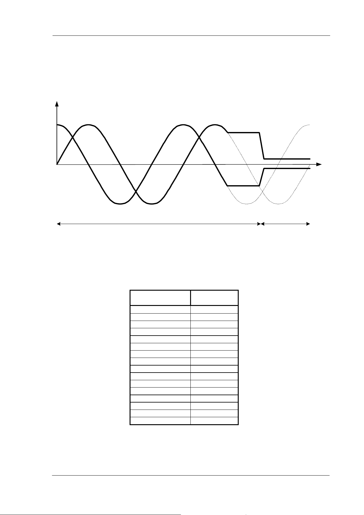
5.3.2 Transition Irun to Ihold
At the end of a motor motion the actual coil currents Irun are maintained in the coils at their actual DC
level for a quarter of an electrical period (two half steps) at minimum velocity. Afterwards the currents
are then set to their hold values Ihold. The figure below illustrates the mechanism:
i
t
I = I
run
I = I
hold
Figure 12: Transition Irun to Ihold
Both currents Irun and Ihold are parameterizeable using the command SetMotorParam. 16 values are
available for Irun current and 16 values for Ihold current. The table below shows the corresponding
current values.
Irun / Ihold setting
(hexadecimal)
Peak Current
[mA]
0x0 59
0x1 71
0x2 84
0x3 100
0x4 119
0x5 141
0x6 168
0x7 200
0x8 238
0x9 283
0xA 336
0xB 400
0xC 476
0xD 566
0xE 673
0xF 800
Table 12: Irun / Ihold Settings
Copyright © 2004-2005 TRINAMIC Motion Control GmbH & Co. KG
Page 24

24 TMC211 DATASHEET (V. 1.04 / January 7, 2005)
5.3.3 Chopper Mechanism
The chopper frequency is fixed as specified in chapter 10.4 AC Parameters on page 55. The TMC211
uses an intelligent chopper algorithm to provide a smooth operation with low resonance. The TMC211
uses internal measurements to derive current flowing through coils. If the current is less than the
desired current, the TMC211 switches a H-bridge in a way that the current will increase. Otherwise if
the current is too high, the H-bridge will be switched to decrease the current. For decreasing two
modes are available, slow decay and fast decay, whereas fast decay decreases the current faster than
slow decay. The figure below shows the chopper behavior.
Figure 13: Different Chopper Cycles with Fast and Slow Decay
Copyright © 2004-2005 TRINAMIC Motion Control GmbH & Co. KG
Page 25

TMC211 DATASHEET (V. 1.04 / January 7, 2005) 25
6 LIN Interface
6.1 General Description
The LIN (Local Interconnect Network) is a serial communication protocol that is used mainly for
distributed mechatronic systems in automotive applications. The LIN implementation in the TMC211
corresponds to one slave node which follows to LIN specification rev. 1.2.
Features:
• Single master / multiple-slave communication
• Self synchronizing slave nodes / no quartz or ceramics resonator necessary
• Deterministic latency times for signal transmission
• Single-wire communication
• Transmission speed 19.2 kbit/s
• Selectable length of Message Frame: 2, 4, and 8 bytes
• Configuration flexibility
• Data checksum security and error detection
• Detection of defective nodes in the network
For more information about the LIN protocol please refer to the official website and the LIN Protocol
Specification. Both can be found at http://www.lin-subbus.org/.
6.2 Physical Layer
The physical layer is a single wire with pull-up resistor in every node. The bus is directly powered from
the vehicle power net V
.
bb
V
bb
LIN
HW0
HW1
HW2
R=30K
R
R
Ω
Wake-Up
INH Ctrl
INH
to 5V
regulator
Receiver
EN
RxD
Driver +
Slope Control
LIN Protocol
Handler
TxD
to control
block
Figure 14: LIN Physical Layer
Copyright © 2004-2005 TRINAMIC Motion Control GmbH & Co. KG
Page 26

26 TMC211 DATASHEET (V. 1.04 / January 7, 2005)
6.3 Analog Part
The transmitter is a low-side driver with a pull-up resistor and slope control. The figure below shows
the characteristics of the transmitted signal, including the delay between internal TxD Signal and LIN
Signal. See Table 32: AC Parameters LIN Transmitter on page 55 and Table 33: AC Parameters LIN
Receiver on page 55 for timing values.
TxD
50%
50%
T_tr_F
LIN
95%
t_slope_F t_slope_R
LIN
50%
RxD
50%
T_rec_F
T_tr_R
60%
40%
5%
50%
T_rec_R
50%
t
100%
0%
t
t
t
Figure 15: LIN Signal Characteristics
6.4 Slave operational range for proper self synchronization
The internal oscillator having a ± 10% accuracy over the voltage and temperature range, will
synchronize properly in the following conditions:
• Vbb ≥ 8 V
• Ground shift between Master node and Slave node < ± 1 Volt
It is highly recommended to use the same type of reverse battery voltage protection diode for the
Master and the Slave nodes.
Copyright © 2004-2005 TRINAMIC Motion Control GmbH & Co. KG
Page 27

TMC211 DATASHEET (V. 1.04 / January 7, 2005) 27
6.5 Physical Address of the circuit
The circuit must be provided with a physical address in order to discriminate this circuit from other
ones on the LIN bus. This address is coded on seven bits, yielding the theoretical possibility of 128
different circuits on the same bus. It is a combination of four OTP memory bits (see 5.2.3 OTP Memory
Structure) and three hardwired address bits (pins HW0, HW1 and HW2). Pins HW0 and HW1 are 5V
digital inputs, whereas pin HW2 is compliant with a 12V level. HW2 must either be connected to Vbat
or ground. Pin HW2 uses the same principle to check whether it is connected to ground or Vbat like
the SWI input (see 5.1.9 External Switch).
The TCM211 supports broadcasting. When the <Broad> bit is set to zero, broadcasting is active and
each slave on the LIN bus will be addressed.
AD5AD6 AD1AD2AD3AD4 AD0
OTP_AD3 OTP_AD1OTP_AD2 OTP_AD0
HW 2HW 1HW0
Figure 16: Physical Slave Address
The amount of physical addresses can be expanded by using bit ADM. This bit allows for the following
expansion:
ADM AD6 AD5 AD4 AD3 AD2 AD1 AD0
0 HW0 HW1 HW2 PA3 PA2 PA1 PA0
1 PA0 HW0 HW1 HW2 PA3 PA2 PA1
Physical address
OTP Memory
Hardwired Bits
Table 13: Physical Address Expansion
6.6 Electro Magnetic Compability
EMC behavior fulfills requirements defined by LIN specification rev. 1.3.
6.7 Error Status Register
The LIN interface implements a register containing an error status of the LIN communication. This
register is specified as follows:
Bit7 Bit6 Bit5 Bit4 Bit3 Bit2 Bit1 Bit0
Not used Not used Not used Not used Timeout
Error Flag
Table 14: LIN Error Status Register
Note:
Data Error Flag = Checksum error OR StopBit error OR Length error
Header Error Flag = Parity error OR Synch Field error
A GetFullStatus command will reset the error status register
Data Error
Flag
Header
Error Flag
Bit Error
Flag
Copyright © 2004-2005 TRINAMIC Motion Control GmbH & Co. KG
Page 28

28 TMC211 DATASHEET (V. 1.04 / January 7, 2005)
6.8 Dynamic Assignment of LIN Identifiers
The identifier field in the LIN message frame denotes the content of the message. Six identifier bits
and two parity bits are used to represent the content. The identifiers 0x3C to 0x3F are reserved for
command frames and extended frames. Slave nodes need to be very flexible to adapt itself to a given
LIN network in order to avoid conflicts with slave nodes from different manufacturers. Dynamic
assignment of identifiers fulfills this requirement by writing identifiers into the circuits RAM. ROM
pointers are linking commands and dynamic identifiers together.
A writing frame with identifier 0x3C issued by the LIN master writes dynamic identifiers into the RAM.
One writing frame is able to assign 4 identifiers, therefore 3 frames are needed to assign all identifiers.
Each ROM pointer ROMp_x [3:0] places the corresponding dynamic identifier Dyn_ID_x [5:0] at the
correct place in the RAM, see table below. When setting <BROAD> to zero broadcasting is active and
each slave on the LIN bus will store the same dynamic identifiers, otherwise only the slave with the
corresponding slave address is programmed.
Dynamic Identifiers Writing Frame
Byte Content Structure
Bit7 Bit6 Bit5 Bit4 Bit3 Bit2 Bit1 Bit0
0 Identifier 0x3C
1 AppCMD 0x80
2 CMD 1 0x11
3 Address Broad AD6 AD5 AD4 AD3 AD2 AD1 AD0
4 Data DynID_1 [3:0] ROMp_1 [3:0]
5 Data DynID_2 [1:0] ROMp_2 [3:0] DynID_1 [5:4]
6 Data ROMp_3 [3:0] DynID_2 [5:2]
7 Data ROMp_4 [1:0] DynID_3 [5:0]
8 Data DynID_4 [5:0] ROMp_4 [3:2]
Dynamic ID
user defined
user defined
user defined
user defined
user defined
user defined
user defined
user defined
user defined
ROM pointer
(binary)
0000
0001
0010
0011
0100
0101
0110
0111
1000
Application command
General purpose 2 data bytes
General purpose 4 data bytes
GetActualPosition
GetStatus
SetPosition (2 data bytes)
SetPositionShort (1 Motor)
SetPositionShort (2 Motors)
SetPositionShort (4 Motors)
Preparation frame
Dynamic assignment done at start-up
Command assignment via Dynamic ID during operation
Figure 17: Principle of dynamic command assignment
Copyright © 2004-2005 TRINAMIC Motion Control GmbH & Co. KG
Page 29

TMC211 DATASHEET (V. 1.04 / January 7, 2005) 29
Command Byte (CMD) Command Mnemonic
binary hex
Dynamic ID
(binary; example)
ROM pointer
(binary)
GetActualPos 000000 0x00 100xxx 0010
GetFullStatus 000001 0x01 Not used
GetOTPParam 000010 0x02 Not used
GetStatus 000011 0x03 000xxx 0011
GotoSecurePosition 000100 0x04 Not used
HardStop 000101 0x05 Not used
ResetPosition 000110 0x06 Not used
ResetToDefault 000111 0x07 Not used
RunInit 001000 0x08 Not used
SetMotorParam 001001 0x09 Not used
SetPosition 001011 0x0B 010xxx 0100
SetPositionShort (1 Motor) 001100 0x0C 001001 0101
SetPositionShort (2 Motors) 001101 0x0D 101001 0110
SetPositionShort (4 Motors) 001110 0x0E 111001 0111
Sleep Not used Not used
SoftStop 001111 0x0F Not used
SetOTPParam 010000 0x10 Not used
Dynamic ID assignment 010001 0x11 Not used
General Purpose 2 Data Bytes 011000 0000
General Purpose 4 Data Bytes 101000 0001
Preparing Frame 011010 1000
Table 15: Commands and Corresponding Dynamic IDs
Note: xxx allows to address physically a slave node. Therefore, these dynamic IDs cannot be used for more than 8 stepper
motors.
6.9 LIN Message Frames
As specified in LIN specification rev. 1.3 a LIN frame consists of an 8-bit identifier field, followed by 2, 4
or 8 data fields and a checksum field. A LIN frame can either be a writing frame, with one of the
following tasks:
• Program the OTP memory
• Provide motion parameters, e.g. velocity, position, torque to the TMC211
Or a LIN frame can be a reading frame which is used to:
• Read actual position or status information of the stepper motor
• Verify correct programming and configuration
6.9.1 Writing Frames
According to the LIN specification there is only a fixed amount of identifiers available. In order to
expand the amount of identifiers resp. the amount of commands different types of writing frames are
introduced. The TMC211 supports four different writing frames. The following figures illustrate the
differences.
Copyright © 2004-2005 TRINAMIC Motion Control GmbH & Co. KG
Page 30

30 TMC211 DATASHEET (V. 1.04 / January 7, 2005)
6.9.2 Writing Frame Type#1 (2 or 4 bytes)
General purpose 2 or 4 data bytes writing frame with a dynamically assigned identifier. This type is
used to provide 2 or 4 bytes of data to the slave nodes. When <Broad> is set to zero, broadcasting is
active and the command is valid for all slave nodes. When <Broad> is one the command is only valid
for one slave node whose physical address corresponds to the one provided by the writing frame.
A writing frame of 2 bytes issues only a defined command to the slave node(s), e.g. HardStop
command. Whereas a writing frame of 4 bytes issues a command and 2 bytes of data to the slave
node(s), e.g. SetPosition command.
ID Data1 Data2
ID [7:0]
Identifier Parameters
Command
Physical
Address
Data3 Data4
BCMD [6:0] 1
6.9.3 Writing Frame Type#2 (2, 4 or 8 bytes)
2, 4 or 8 data bytes writing frame with an identifier dynamically assigned to a particular application
command, regardless of the physical address of the circuit. e.g. SetPositionShort command.
ID Data1 Data2
ID [5:0] B
Dynamic
Identifier
pp
AD [3:0]
physi cal
address
Parameter [10:0]
6.9.4 Writing Frame Type#3 (2 bytes)
2 data bytes writing frame with an identifier dynamically assigned to a particular slave node and
application command. This type of frame requires that there are as many dynamically assigned
identifiers as there are TMC211 circuits connected to the LIN bus using this command.
ID Data1 Data2
ID [5:0] pp
Dynamic
Identifier
Parameter [15:0]
6.9.5 Writing Frame Type#4 (8 bytes)
8 data bytes writing frame with fixed identifier 0x3C. The structure is similar to type#1 but uses the
reserved identifier 0x3C. Using a reserved identifier followed by a particular application command will
expand the amount of possible LIN commands.
ID Data1 Data2 Data4Data3 Data5 Data6 Data7 Data8
0x3C 00 0x80 CMD [6:0] 1 B
physical
address
Parameters send from LIN master to LIN slave nodefixed identifier AppCMD Command
Copyright © 2004-2005 TRINAMIC Motion Control GmbH & Co. KG
Page 31

TMC211 DATASHEET (V. 1.04 / January 7, 2005) 31
6.9.6 Reading Frames
When using reading frames the master initiates the communication by sending a header field, which
contains the synchronization and identifier field. The TMC211 supports two types of identifiers:
• Direct ID: The identifier points to a particular slave node. As described in the LIN specification the
slave sends the data as in-frame response. Direct ID gives the fastest access to the required data.
• Indirect ID: Indirect ID contains of two datagrams. The first datagram, called preparing frame,
issues the slave’s physical address to the particular slave node. The second datagram specifies
only a reading command by using the reserved identifier 0x3D. Indirect ID has the advantage to
use a reserved identifier and therefore provides more flexibility.
6.9.7 Reading Frame Type#5 (2, 4 or 8 bytes)
Type#5 is a reading frame, which uses a direct ID, therefore the master initiates the communication
and the slave responds after receiving the identifier. Dependent on the identifier the slave transmits 2,
4 or 8 bytes of data. GetActualPos command uses Type#5 reading frame.
Master
Task
In-Frame
Slave
Sy nch B reak
Sy nch Fie ld
ID
ID [5:0]
Dynamic
Identifier
pp
Data1 Data2
Data8Datax
Response
(2, 4 or 8 bytes)
Parameters back to master
6.9.8 Reading Frame Type#6 (8 bytes)
Reading frame Type#6 uses indirect ID and therefore a preparing frame of Type#7 or #8 is needed.
The preparing frame dumps the reading command into a particular slave node. Data from the slave is
then transmitted after the next reading frame. The reading frame must always be consecutive to a
preparing frame, otherwise it is not valid and not taken into account.
Master Task 1.
Master Task 2.
(Reading Frame)
Slave
Response
(8 bytes)
Preparing Frame Type#7 or Type#8
ID
ID [7:0]
Sy nch Br eak
Sy nch Fi el d
Identifier
0x3D
Data1 Data2
Parameters back to master
Data8Datax
Copyright © 2004-2005 TRINAMIC Motion Control GmbH & Co. KG
Page 32

32 TMC211 DATASHEET (V. 1.04 / January 7, 2005)
6.9.9 Reading Frame Type#7 (Preparing frame)
A preparing frame prepares a particular slave node, that it has to answer after the next reading frame.
Preparing frames are needed when using indirect ID. Type#7 preparing frame consists of a
dynamically assigned identifier, the command indicating which kind of information is to provide to the
master and the physical address of the slave.
ID Data1 Data2
ID [7:0]
Identifier
CMD [6:0]
Command
AD [6:0]
Physical
Address
6.9.10 Reading Frame Type#8 (Preparing frame)
Type#8 preparing frame uses the reserved identifier 0x3C, followed by the application command 0x80,
then the particular reading command and the physical address is provided to the slave.
ID
ID [7:0]
Identifier
0x3C
Data1 Data2 Data3 Data4 Data8
AppCMD [7:0]
AppCMD
0x80
CMD [6:0]
Command
AD [6:0] 0xFF 0xFF
Slave
Address
0xFF
Data 4...8 = 0xFF
Copyright © 2004-2005 TRINAMIC Motion Control GmbH & Co. KG
Page 33

TMC211 DATASHEET (V. 1.04 / January 7, 2005) 33
6.10 Application Commands Overview
Communications between the TMC211 and a LIN Master takes place via a set of commands.
Reading commands are used to:
• Get actual status information, e.g. error flags
• Get actual position of the Stepper Motor
• Verify the right programming and configuration of the TMC211
Writing commands are used to:
• Program the OTP Memory
• Configure the TMC211 with motion parameters (e.g. max/min speed, acceleration, stepping mode,
etc.)
• Provide target positions to the Stepper motor
Command Mnemonic Function
GetActualPos Returns actual position of the motor
GetFullStatus Returns actual, target and secure position and also the complete
status of the circuit
GetOTPParam Returns OTP memory content
GetStatus Returns quick status of the circuit
GotoSecurePosition Drives motor to secure position
HardStop Immediate full stop
ResetPosition Actual and target position becomes zero
ResetToDefault Overwrites the chip RAM with OTP contents
RunInit Reference Search
SetMotorParam Sets motor parameter
SetPosition Drives the motor to the target position
SetPositionShort (1 Motor) Drives the motor to the target position (Half stepping mode only)
SetPositionShort (2 Motors) Drives 2 motors to the target position (Half stepping mode only)
SetPositionShort (4 Motors) Drives 4 motors to the target position (Half stepping mode only)
SoftStop Stops the motor with deceleration phase
SetOTPParam Programs the selected byte of OTP memory
Sleep Causes circuit to go into sleep mode
Table 16: Command Overview
Copyright © 2004-2005 TRINAMIC Motion Control GmbH & Co. KG
Page 34

34 TMC211 DATASHEET (V. 1.04 / January 7, 2005)
6.11 Command Description
6.11.1 GetActualPos
This command is provided to the circuit by the LIN master to get the actual position of the stepper
motor. GetActualPos provides also a quick status of the circuit and of the stepper motor, identical to
that obtained by command GetFullStatus. The GetActualPos will not attempt to reset any flags. This
command can be sent using direct or indirect ID:
1. Direct ID (immediate in-frame slave response):
GetActualPos direct ID reading frame(type#5)
Structure Source Byte Content
bit 7 bit 6 bit 5 bit 4 bit 3 bit 2 bit 1 bit 0
Master 0 Identifier * * 1 0 ID3 ID2 ID1 ID0
1 Slave Address ESW AD [6:0]
Slave
Note: * according to parity calculation
Or:
2. Indirect ID (preparing frame followed by indirect ID reading frame):
Master
Note: * according to parity calculation
Master
2 Actual Position ActPos [15:8]
3 ActPos [7:0]
4 Status
ID [3:0]: Dynamically allocated identifier to GetActualPos command.
VddReset StepLoss
ElDef UV2 TSD TW Tinfo [1:0]
The master sends either type#7 or type#8 preparing frame:
GetActualPos preparing frame (type#7)
Structure Source Byte Content
bit 7 bit 6 bit 5 bit 4 bit 3 bit 2 bit 1 bit 0
0 Identifier * * 0 ID4 ID3 ID2 ID1 ID0
1 Command 1 CMD [6:0] = 0x00
2 Slave Address 1 AD [6:0]
ID [4:0]: Dynamically allocated identifier to type#7 preparing frame.
GetActualPos preparing frame (type#8)
Structure Source Byte Content
bit 7 bit 6 bit 5 bit 4 bit 3 bit 2 bit 1 bit 0
0 Identifier 0 0 1 1 1 1 0 0
1 AppCMD AppCMD = 0x80
2 Command 1 CMD [6:0] = 0x00
3 Slave Address 1 AD [6:0]
4 Data4 0xFF
5 Data5 0xFF
6 Data6 0xFF
7 Data7 0xFF
8 Data8 0xFF
Copyright © 2004-2005 TRINAMIC Motion Control GmbH & Co. KG
Page 35

TMC211 DATASHEET (V. 1.04 / January 7, 2005) 35
After type#7 or type#8 preparing frame the master sends reading frame type#6 to retrieve the
circuit’s in-frame response:
GetActualPos indirect ID reading frame (type#6)
Structure Source Byte Content
bit 7 Bit 6 bit 5 bit 4 bit 3 bit 2 bit 1 bit 0
Master 0 Identifier 0 1 1 1 1 1 0 1
1 Slave Address 1 AD [6:0]
2 ActualPosition ActPos [15:8]
3 ActPos [7:0]
Slave
4 Status
5 Do not care 0xFF
VddReset StepLoss
ElDef UV2 TSD TW Tinfo [1:0]
6 Do not care 0xFF
7 Do not care 0xFF
8 Do not care 0xFF
Copyright © 2004-2005 TRINAMIC Motion Control GmbH & Co. KG
Page 36

36 TMC211 DATASHEET (V. 1.04 / January 7, 2005)
6.11.2 GetFullStatus
This command is provided to the circuit by the Master to get a complete status of the circuit and of the
Stepper-motor. The parameters sent via LIN interface to the master are:
• coil peak and hold currents value (Irun and Ihold)
• maximum and minimum velocities for the Stepper-motor (Vmax and Vmin)
• direction of motion clockwise / counterclockwise (Shaft)
• stepping mode (StepMode) (Table 11: StepMode on page 21)
• acceleration (deceleration) for the Stepper motor (Acc)
• acceleration shape (AccShape)
• status information (see further)
• motion status <Motion [2:0]>
• over current flags for coil #1 <OVC1> and coil #2 <OVC2>
• digital supply reset <VddReset>
• charge pump status <CPFail>
• external switch status <ESW>
• step loss <StepLoss>
• electrical defect <ElDef>
• under voltage <UV2>
• temperature information <Tinfo>
• temperature warning <TW>
• temperature shutdown <TSD>
The following flags are attempt to reset:
<TW>, <TSD>, <UV2>, <ElDef>, <StepLoss>, <CPFail>, <OVC1>, <OVC2> and <VddReset>
The master sends either type#7 or type#8 preparing frame:
GetFullStatus preparing frame (type#7)
Structure Source Byte Content
bit 7 bit 6 bit 5 bit 4 bit 3 bit 2 bit 1 bit 0
0 Identifier * * 0 ID4 ID3 ID2 ID1 ID0
Master
1 Command 1 CMD [6:0] = 0x01
2 Slave Address 1 AD [6:0]
Note: * according to parity calculation
ID [4:0]: Dynamically allocated identifier to type#7 preparing frame.
GetFullStatus preparing frame (type#8)
Structure Source Byte Content
bit 7 bit 6 bit 5 bit 4 bit 3 bit 2 bit 1 bit 0
0 Identifier 0 0 1 1 1 1 0 0
1 AppCMD AppCMD = 0x80
2 Command 1 CMD [6:0] = 0x01
3 Slave Address 1 AD [6:0]
Master
4 Data4 0xFF
5 Data5 0xFF
6 Data6 0xFF
7 Data7 0xFF
8 Data8 0xFF
Copyright © 2004-2005 TRINAMIC Motion Control GmbH & Co. KG
Page 37

TMC211 DATASHEET (V. 1.04 / January 7, 2005) 37
After type#7 or type#8 preparing frame the master sends two successive LIN type#6 reading frames to
retrieve the circuit’s in-frame responses. It is not mandatory to send the second reading frame if
position information are not needed by the application.
GetFullStatus indirect ID reading frame 1 (type#6)
Structure Source Byte Content
bit 7 bit 6 Bit 5 bit 4 bit 3 bit 2 bit 1 bit 0
Master 0 Identifier 0 1 1 1 1 1 0 1
1 Slave Address 1 AD [6:0]
2 Irun + Ihold Irun [3:0] Ihold [3:0]
3 Vmax + Vmin Vmax [3:0] Vmin [3:0]
Acc Shape StepMode [1:0]
VddReset StepLoss
ElDef UV2 TSD TW Tinfo [1:0]
See Table 14: LIN Error Status Register on page 27
Shaft Acc [3:0]
CPFail
Slave
4 Status + Acc
5 Status
6 Status Motion [2:0] ESW OVC1 OVC2 1
7 LIN error
status register
8 Do not care 0xFF
GetFullStatus indirect ID reading frame 2 (type#6)
Structure Source Byte Content
bit 7 bit 6 Bit 5 bit 4 bit 3 bit 2 bit 1 bit 0
Master 0 Identifier 0 1 1 1 1 1 0 1
1 Slave Address 1 AD [6:0]
2 ActualPosition ActPos [15:8]
3 ActPos [7:0]
Slave
4 TargetPosition TagPos [15:8]
5 TagPos [7:0]
6 SecurePosition SecPos [7:0]
7 1 1 1 1 1 SecPos [10:8]
8 Do not care 0xFF
Copyright © 2004-2005 TRINAMIC Motion Control GmbH & Co. KG
Page 38

38 TMC211 DATASHEET (V. 1.04 / January 7, 2005)
6.11.3 GetOTPParam
This command is provided to the circuit by the master to read the content of the OTP Memory. For
more information refer to Table 9: OTP Memory Structure on page 21.
The master sends either type#7 or type#8 preparing frame:
GetOTPParam preparing frame (type#7)
Structure Source Byte Content
bit 7 bit 6 Bit 5 bit 4 bit 3 bit 2 bit 1 bit 0
0 Identifier * * 0 ID4 ID3 ID2 ID1 ID0
Master
1 Command 1 CMD [6:0] = 0x02
2 Slave Address 1 AD [6:0]
Note: * according to parity calculation
ID [4:0]: Dynamically allocated identifier to type#7 preparing frame.
GetOTPParam preparing frame (type#8)
Structure Source Byte Content
bit 7 bit 6 bit 5 bit 4 bit 3 bit 2 bit 1 bit 0
0 Identifier 0 0 1 1 1 1 0 0
1 AppCMD AppCMD = 0x80
2 Command 1 CMD [6:0] = 0x02
3 Slave Address 1 AD [6:0]
Master
4 Data4 0xFF
5 Data5 0xFF
6 Data6 0xFF
7 Data7 0xFF
8 Data8 0xFF
After type#7 or type#8 preparing frame the master sends a type#6 reading frame to retrieve the
circuit’s in-frame response:
GetOTPParam indirect ID reading frame (type#6)
Structure Source Byte Content
Bit 7 bit 6 bit 5 bit 4 bit 3 bit 2 bit 1 bit 0
Master 0 Identifier 0 1 1 1 1 1 0 1
1 OTP Memory OTP byte @0x00
2 OTP Memory OTP byte @0x01
3 OTP Memory ADM HW2 HW1 HW0 PA3 PA2 PA1 PA0
Slave
4 OTP Memory OTP byte @0x03
5 OTP Memory OTP byte @0x04
6 OTP Memory OTP byte @0x05
7 OTP Memory OTP byte @0x06
8 OTP Memory OTP byte @0x07
HW[2:0]: Not stored in OTP memory, the hardwired address is returned by GetOTPParam as if stored
at address 0x02 of the OTP memory.
Copyright © 2004-2005 TRINAMIC Motion Control GmbH & Co. KG
Page 39

TMC211 DATASHEET (V. 1.04 / January 7, 2005) 39
6.11.4 GetStatus
This command is provided to the circuit by the LIN master to get a quick status (compared to that of
GetFullStatus command) of the circuit and the stepper motor.
The following flags are attempt to reset:
<TW>, <TSD>, <UV2>, <ElDef>, <StepLoss>, <CPFail>, <OVC1>, <OVC2> and <VddReset>
GetStatus direct ID reading frame (type#5)
Structure Source Byte Content
Bit 7 bit 6 bit 5 Bit 4 bit 3 bit 2 bit 1 bit 0
Master 0 Identifier * * 0 ID4 ID3 ID2 ID1 ID0
Slave
Note: * according to parity calculation
ID [4:0]: Dynamically allocated identifier to GetStatus command.
1 Slave Address ESW AD [6:0]
2 Status
VddReset StepLoss
ElDef UV2 TSD TW Tinfo[1:0]
6.11.5 GotoSecurePosition
This command is provided by the LIN master to one or all stepper motors to move to the secure
position SecPos[10:0]. It can also be triggered if the LIN communication is lost or at the end of a
RunInit initialization phase. If <Broad> is set to zero all stepper motors connected to the LIN bus will
reach their secure position. If SecPos[10:0] equals 0x400 (the most negative decimal value of –1024)
the secure position is disabled and the GotoSecurePosition command is ignored.
GotoSecurePosition general purpose writing frame (type#1)
Structure Source Byte Content
bit 7 bit 6 bit 5 Bit 4 bit 3 bit 2 bit 1 bit 0
0 Identifier * * 0 ID4 ID3 ID2 ID1 ID0
Master
Note: * according to parity calculation
1 Command 1 CMD [6:0] = 0x04
2 Slave Address
ID [4:0]: Dynamically allocated identifier to general purpose 2 data bytes writing frame.
Broad
AD [6:0]
6.11.6 HardStop
This command is internally triggered when an electrical problem is detected in one or both coils,
leading to switching off of the H-bridges. If this problem is detected while the motor is moving, the
<StepLoss> flag is raised allowing to warn the Master with the next GetStatus command that steps
may have been lost. A HardStop command can also be issued by the Master for some safety reasons.
If <Broad> is set to zero all the stepper motors connected to the LIN bus will stop.
HardStop general purpose writing frame (type#1)
Structure Source Byte Content
bit 7 bit 6 bit 5 Bit 4 bit 3 bit 2 bit 1 bit 0
0 Identifier * * 0 ID4 ID3 ID2 ID1 ID0
Master
1 Command 1 CMD [6:0] = 0x05
2 Slave Address Broad AD [6:0]
Note: * according to parity calculation
ID [4:0]: Dynamically allocated identifier to general purpose 2 data bytes writing frame.
Copyright © 2004-2005 TRINAMIC Motion Control GmbH & Co. KG
Page 40

40 TMC211 DATASHEET (V. 1.04 / January 7, 2005)
6.11.7 ResetPosition
This command is provided to the circuit by the Master to reset ActPos and TagPos registers, in order
to allow for an initialization of the Stepper-motor position. If <Broad> is set to zero all circuits connected
to the LIN bus will reset their ActPos and TagPos registers.
: This command is ignored during motion. It has no effect during motion. The Status Flags (section
Hint
5.2.2, page 20) named 'Motion Status' indicate if the motor is at rest (velocity=0).
ResetPosition general purpose writing frame (type#1)
Structure Source Byte Content
bit 7 bit 6 bit 5 Bit 4 bit 3 bit 2 bit 1 bit 0
0 Identifier * * 0 ID4 ID3 ID2 ID1 ID0
Master
1 Command 1 CMD [6:0] = 0x06
2 Slave Address Broad AD [6:0]
Note: * according to parity calculation
ID [4:0]: Dynamically allocated identifier to general purpose 2 data bytes writing frame.
6.11.8 ResetToDefault
This command is provided to the circuit by the Master in order to reset the whole Slave node into the
initial state. ResetToDefault for instance overloads the RAM contents with the reset state of the
parameters. This is another way for the Master to initialize a slave node in case of emergency, or
simply to refresh the RAM content.
Note: ActPos is not modified by a ResetToDefault command, and it’s value is copied into TagPos
register in order to avoid an attempt to position the motor to ‘0’. If <Broad> is set to zero all circuits
connected to the LIN bus will reset to default.
ResetToDefault general purpose writing frame (type#1)
Structure Source Byte Content
bit 7 bit 6 Bit 5 Bit 4 bit 3 bit 2 bit 1 bit 0
0 Identifier * * 0 ID4 ID3 ID2 ID1 ID0
Master
1 Command 1 CMD [6:0] = 0x07
2 Slave Address Broad AD [6:0]
Note: * according to parity calculation
ID [4:0]: Dynamically allocated identifier to general purpose 2 data bytes writing frame.
Copyright © 2004-2005 TRINAMIC Motion Control GmbH & Co. KG
Page 41

TMC211 DATASHEET (V. 1.04 / January 7, 2005) 41
6.11.9 RunInit
This command is provided to the circuit by the Master in order to initialize positioning of the motor by
seeking the zero (or reference) position. Refer to 5.1.11 Reference Search / Position initialization on
page 14. It leads to a sequence of the following commands:
• SetMotorParam(Vmax, Vmin);
• SetPosition(Pos1);
• SetMotorParam(Vmin, Vmin);
• SetPosition(Pos2);
• ResetPosition
• GotoSecurePosition
Once the RunInit command is started it can not be interrupted by any other command. Except a
condition occurs which leads to a motor shutdown (See 5.1.10 Motor Shutdown Management) or a
HardStop command is received. If SecPos[10:0] equals 0x400 (the most negative decimal value of
-1024) the final travel to the secure position is omitted.
The master has to ensure that the target position of the first motion is not equal to the actual position
of the stepper motor and that the target positions of the first and second motion are different, too. This
is very important, otherwise the circuit goes into a deadlock state. Once the circuit is in deadlock state
only a HardStop command followed by a GetFullStatus command will cause the circuit to leave the
deadlock state. If <Broad> is set to zero all circuits connected to the LIN bus will run the init sequence.
RunInit reserved ID writing frame (type#4)
Structure Source Byte Content
bit 7 bit 6 Bit 5 Bit 4 bit 3 bit 2 bit 1 bit 0
0 Identifier 0 0 1 1 1 1 0 0
1 AppCMD AppCMD = 0x80
2 Command 1 CMD [6:0] = 0x08
3 Slave Address Broad AD [6:0]
Master
4 Vmax + Vmin Vmax [3:0] Vmin [3:0]
5 Target Position 1 Pos1 [15:8]
6 Pos1 [7:0]
7 Target Position 2 Pos2 [15:8]
8 Pos2 [7:0]
Note: Vmax [3:0]: Maximum Velocity for first motion of the run
Vmin [3:0]: Minimum Velocity for first motion and maximum velocity for the second motion of the run
Pos1 [15:0]: First target position to be reached during the init run.
Pos2 [15:0]: Second target position to be reached during the init run.
Copyright © 2004-2005 TRINAMIC Motion Control GmbH & Co. KG
Page 42

42 TMC211 DATASHEET (V. 1.04 / January 7, 2005)
6.11.10 SetMotorParam
This command is provided to the circuit by the Master to set the values for the Stepper motor
parameters in RAM. Note: it is not recommended to change Vmax, Vmin or Acc while a motion is
ongoing, otherwise correct positioning is not guaranteed. The following parameter values are set in
RAM:
• coil peak current value (Irun)
• coil hold current value (Ihold)
• maximum velocity for the Stepper-motor (Vmax)
• minimum velocity for the Stepper-motor (Vmin)
• acceleration shape (AccShape)
• stepping mode (StepMode)
• indicator of the Stepper-motor moving direction (Shaft)
• acceleration (deceleration) for the Stepper-motor (Acc)
• secure position for the Stepper-motor (SecPos)
If <Broad> is set to zero all stepper motors connected to the LIN bus will set the parameters in their
RAMs. If SecPos[10:0] is set to 0x400 (the most negative decimal value of –1024) the secure position
is disabled and the GotoSecurePosition command is ignored.
SetMotorParam reserved ID writing frame (type#4)
Structure Source Byte Content
bit 7 bit 6 bit 5 Bit 4 bit 3 bit 2 bit 1 bit 0
0 Identifier 0 0 1 1 1 1 0 0
1 AppCMD AppCMD = 0x80
2 Command 1 CMD [6:0] = 0x09
3 Slave Address Broad AD [6:0]
Master
4 Irun + Ihold Irun [3:0] Ihold [3:0]
5 Vmax + Vmin Vmax [3:0] Vmin [3:0]
6 SecPos + Acc SecPos [10:8] Shaft Acc [3:0]
7 Secure Position2 SecPos [7:0]
8 Status 1 1 1
Acc
Shape
StepMode [1:0]
1 1
6.11.11 SetOTPParam
This command is provided to the circuit by the Master in order to zap the OTP memory. If <Broad> is
set to zero all circuits connected to the LIN bus will zap their OTP memories. Please refer to Table 25:
DC Parameters Supply and Voltage regulator on page 54 to ensure that the correct supply voltage is
applied to the chip, otherwise the circuit will be damaged.
SetOTPParam with reserved ID (type#4)
Structure Source Byte Content
bit 7 bit 6 bit 5 Bit 4 bit 3 bit 2 bit 1 bit 0
0 Identifier 0 0 1 1 1 1 0 0
1 AppCMD AppCMD = 0x80
2 Command 1 CMD [6:0] = 0x10
3 Slave Address Broad AD [6:0]
Master
4 OTP Address 1 1 1 1 1 OTPA [2:0]
5 OTP Data Data [7 :0]
6 Do not care 0xFF
7 Do not care 0xFF
8 Do not care 0xFF
Copyright © 2004-2005 TRINAMIC Motion Control GmbH & Co. KG
Page 43

TMC211 DATASHEET (V. 1.04 / January 7, 2005) 43
6.11.12 SetPosition
This command is provided to the circuit by the Master to drive a motor to a given position relative to the
zero position, defined in number of half or micro steps, according to StepMode[1:0] value.
SetPosition will not be performed if one of the following flags is set to one:
• temperature shutdown <TSD>
• under voltage <UV2>
• step loss <StepLoss>
• electrical defect <ElDef>
This command can be sent using dynamic ID, general purpose ID or reserved ID:
1. Dynamic ID:
SetPosition dynamic ID writing frame (type#3)
Structure Source Byte Content
bit 7 bit 6 bit 5 Bit 4 bit 3 bit 2 bit 1 bit 0
0 Identifier * * 0 ID4 ID3 ID2 ID1 ID0
Master
1 TargetPosition TagPos [15:8]
2 TagPos [7:0]
Note: * according to parity calculation
ID [4:0]: Dynamically allocated identifier to SetPosition command for a specific slave.
2. General purpose ID:
SetPositon general purpose writing frame (type#1)
Structure Source Byte Content
bit 7 bit 6 bit 5 Bit 4 bit 3 bit 2 bit 1 bit 0
0 Identifier * * 1 0 ID3 ID2 ID1 ID0
1 Command 1 CMD [6:0] = 0x0B
Master
2 Slave Address Broad AD [6:0]
3 Target Position TagPos [15:8]
4 TagPos [7:0]
Note: * according to parity calculation.
ID [3:0]: Dynamically allocated identifier to general purpose 4 data bytes writing frame
If <Broad> is set to zero all stepper motors connected to the LIN bus are going to TagPos.
3. Reserved ID (SetPosition for two motors):
SetPosition for 2 motors with reserved ID (type#4)
Structure Source Byte Content
bit 7 bit 6 bit 5 Bit 4 bit 3 bit 2 bit 1 bit 0
0 Identifier 0 0 1 1 1 1 0 0
1 AppCMD AppCMD = 0x80
2 Command 1 CMD [6:0] = 0x0B
3 Slave Address 1 1 AD1 [6:0]
Master
4 Target Position 1 TagPos1 [15:8]
5 TagPos1 [7:0]
6 Slave Address 2 1 AD2 [6:0]
7 Target Position 2 TagPos2 [15:8]
8 TagPos2 [7:0]
Note: ADn [6:0]: Motor #n physical address
TagPosn [15:0]: Signed 16-bit position set-point for motor #n.
Copyright © 2004-2005 TRINAMIC Motion Control GmbH & Co. KG
Page 44

44 TMC211 DATASHEET (V. 1.04 / January 7, 2005)
6.11.13 SetPositionShort
This command is provided to the circuit by the LIN master to drive one, two or four motors to a given
absolute position. This command is valid for half stepping mode (<StepMode> = “00”) and is ignored
for other stepping modes. If <Broad> is set to zero all circuits connected to the LIN bus will go to the
desired position (only valid for SetPositionShort (1 Motor)).
The physical address is coded on 4 bits, hence SetPositionShort can only be used within a network
implementing a maximum of 16 slave nodes. These 4 bits are normally corresponding to the bits
PA [3:0] in OTP memory (Address 0x00), while bits AD [6:4] must be at ‘1’. Two different cases must in
fact be considered, depending on the programmed value of bit ADM in the OTP memory. See 5.2.3
OTP Memory Structure on page 21.
ADM AD[3] Pin HW0 Pin HW1 Pin HW2 Bit PA0 in
OTP memory
0 X Tied to Vbat AD[0]
1 0 Tied to Gnd 1
1 1
Tied to Vdd
Tied to Vbat 1
Table 17: ADM bit in SetPositionShort Command
SetPositionShort (1 Motor) with dynamic ID (type#2)
Structure Source Byte Content
bit 7 bit 6 bit 5 Bit 4 bit 3 Bit 2 bit 1 bit 0
0 Identifier * * 0 ID4 ID3 ID2 ID1 ID0
Master
1 Slave Address Pos [10:8] Broad AD [3:0]
2 Target Position Pos [7:0]
Note: * according to parity calculation
ID [4:0]: Dynamically allocated identifier to SetPositionShort command with 2 data bytes.
SetPositionShort (2 Motors) with dynamic ID (type#2)
Structure Source Byte Content
bit 7 Bit 6 bit 5 Bit 4 bit 3 bit 2 bit 1 bit 0
0 Identifier * * 1 0 ID3 ID2 ID1 ID0
1 Slave Address 1 Pos1 [10:8] 1 AD1 [3:0]
Master
2 Target Position 1 Pos1 [7:0]
3 Slave Address 2 Pos2 [10:8] 1 AD2 [3:0]
4 Target Position 2 Pos2 [7:0]
SetPositionShort (4 Motors) with dynamic ID (type#2)
Structure Source Byte Content
bit 7 Bit 6 bit 5 Bit 4 bit 3 bit 2 bit 1 bit 0
0 Identifier * * 1 1 ID3 ID2 ID1 ID0
1 Slave Address 1 Pos1 [10:8] 1 AD1 [3:0]
2 Target Position 1 Pos1 [7:0]
3 Slave Address 2 Pos2 [10:8] 1 AD2 [3:0]
Master
4 Target Position 2 Pos2 [7:0]
5 Slave Address 3 Pos3[10:8] 1 AD3 [3:0]
6 Target Position 3 Pos3 [7:0]
7 Slave Address 4 Pos4[10:8] 1 AD4 [3:0]
8 Target Position 4 Pos4 [7:0]
Note: * according to parity calculation
ID [3:0]: Dynamically allocated identifier to SetPositionShort command with 8 data bytes.
ADn [3:0]: Motor #n physical address least significant bits
Posn [10:0]: Unsigned 11-bit position set point for Motor #n
Copyright © 2004-2005 TRINAMIC Motion Control GmbH & Co. KG
Page 45

TMC211 DATASHEET (V. 1.04 / January 7, 2005) 45
6.11.14 SoftStop
If a SoftStop command occurs during a motion of the Stepper motor, it provokes an immediate
deceleration to Vmin followed by a stop, regardless of the position reached. Once the motor is stopped
TagPos register is overwritten with the value in ActPos register to ensure keeping the stop position.
This command is executed if:
• the chip temperature rises the Thermal shutdown threshold or
• the Master sends a SoftStop command
If <Broad> is set to zero all the stepper motors connected to the LIN bus will stop with deceleration.
SoftStop general purpose writing frame (type#1)
Structure Source Byte Content
bit 7 Bit 6 bit 5 Bit 4 bit 3 bit 2 bit 1 bit 0
0 Identifier * * 0 ID4 ID3 ID2 ID1 ID0
Master
1 Command 1 CMD [6:0] = 0x0F
2 Slave Address Broad AD [6:0]
Note: * according to parity calculation
ID [4:0]: Dynamically allocated identifier to general purpose 2 data bytes writing frame.
6.11.15 Sleep Mode
According to LIN specification rev. 1.3, sleep mode and stand-by mode (wake-up) are implemented.
The interface can work in one of the following modes (refer to Figure 14: LIN Physical Layer):
• Normal mode: EN = ‘1’, Vdd = high, INH = ‘1’
• Sleep mode: in the normal mode EN is set to ‘0’ to go to sleep mode after reception of a LIN Sleep
command or more than 25,000 bit times (1.30 seconds) of LIN bus inactivity. The interface current
consumption is limited to Isleep. Only the receiver is working.
• Stand-by mode (wake-up): when a LIN message frame is received in sleep mode or when Vbb
goes high (power-on), INH is immediately activated. The initial state of INH signal is ensured by an
internal power-on-reset circuitry inside the wake-up control.
The TMC211 can be immediately forced to sleep mode to reduce current consumption down to Isleep
by sending the sleep mode command depicted below:
Sleep Mode Command with reserved ID (type#4)
Structure Source Byte Content
bit 7 bit 6 bit 5 Bit 4 bit 3 bit 2 bit 1 bit 0
0 Identifier 0 0 1 1 1 1 0 0
1 Sleep 0x00
2 0xFF
3 0xFF
Master
4 0xFF
5 0xFF
6 0xFF
7 0xFF
8 0xFF
Copyright © 2004-2005 TRINAMIC Motion Control GmbH & Co. KG
Page 46

46 TMC211 DATASHEET (V. 1.04 / January 7, 2005)
6.12 Positioning Task Example
The TMC211 has to perform a positioning task, where the actual position of the stepper motor is
unknown. The desired target position is 3000 µsteps away from position 0. See Figure 18: Positioning
Example: Initial situation.
Stop
?
Actual
Position
=
unknown
?
Target
Position
= 3000
?
X [µsteps]
Position 0
Figure 18: Positioning Example: Initial situation
The following sequence of commands has to be sent to the slave in order to complete the scenario
described above (assumed after power on):
GetFullStatus
The command is used to read the current status of the TMC211. Electrical or environmental problems
will be reported, furthermore the circuit leaves the shutdown state and is ready for action.
Furthermore the circuit provides the actual and target position. This information is very important,
because if the actual position corresponds to the first target position of the RunInit command the circuit
will enter a deadlock state. The master must take care that both positions are containing different
values.
See 6.11.2 GetFullStatus command on page 36 and for deadlock problems see 5.1.11 Reference
Search / Position initialization on page 14.
SetMotorParam
In order to drive the stepper motor with desired motion parameters like torque, velocity, a.s.o.. the
SetMotorParam command must issued. See 6.11.10 SetMotorParam on page 42.
RunInit
Hence the actual position is unknown, a position initialization has to be performed. The first motion
must drive the stepper motor into the stop for sure. The second motion is a very short motion to bring
the motor out of the stop. The actual position is then set to zero automatically after the second motion
is finished. See 6.11.9 RunInit command on page 41.
After reference search the actual situation looks like as described in Figure 19: Positioning Example:
Situation after reference search. Actual position of the stepper motor corresponds to zero, the target
position is 3000 µsteps away from the actual position.
Stop
Actual
Position
= 0
Target
Position
= 3000
X [µsteps]
Figure 19: Positioning Example: Situation after reference search
Now the positioning command SetPosition can be issued in order to drive the stepper motor to the
desired position.
Copyright © 2004-2005 TRINAMIC Motion Control GmbH & Co. KG
Page 47

TMC211 DATASHEET (V. 1.04 / January 7, 2005) 47
SetPosition
This command will cause the stepper motor to move to the desired target position. See 6.11.12
SetPosition on page 42. After the motion has been finished the situation looks like as described in
Figure 20: Positioning Example: Motion finished.
Stop
Actual Position
= Target Position
= 3000
X [µsteps]
Figure 20: Positioning Example: Motion finished
Afterwards the actual status and position can be verified by using GetFullStatus commands. The
master can check if a problem, caused by electrical or temperature problems, occurred. Furthermore
the actual position is read.
Copyright © 2004-2005 TRINAMIC Motion Control GmbH & Co. KG
Page 48

48 TMC211 DATASHEET (V. 1.04 / January 7, 2005)
7 Frequently Asked Questions
7.1 Using the bus interface
Q: How many devices can be operated on the same bus?
A: 128 devices can be discriminated by means of the physical address. However, it depends on some
factors if this high number really makes sense. First of all it has to be checked if each device can be
serviced under any circumstances in the maximum allowed time taking the bus speed and the
individual real-time requirements of each device into account. Second, the idea of reserving address 0
for OTP physical address programming during system installation and defective parts replacement
reduces the number to 120. Third, the TMC211 has faster and slower types of the GetActualPos,
GetStatus and SetPosition commands. The faster types of course can satisfy harder real-time
requirements but can only be addressed to 8 different physical devices. If the faster types shall be
used only 8 TMC211 devices can be connected to the same LIN bus.
Q: How to program the OTP physical address bits of a device if there are more devices
connected to the same bus?
A: The problem here is that all new devices are shipped with the OTP physical address bits set to zero
making it difficult to address just one device with the SetOTPParam command. Use HW0, HW1 or
HW2 input as chip select line to address just one device by SetOTPParam. If this is impractible since
the HW0/HW1/HW2 inputs are hardwired or not controllable for any other reason the only alternative is
to assemble and program one device after the other. I.e., assemble only first device and program the
desired non-zero address, then assemble the second device and program the desired non-zero
address, and so on until all devices are assembled and programmed. This is also a good service
concept when replacing defective devices in the field: The idea is that all devices are programmed to
different non-zero physical addresses at production/installation time. Once a defective device is being
replaced the replacement part can easily be addressed by SetOTPParam since it is the only part with
physical address zero.
7.2 General problems when getting started
Q: What is the meaning of ElDef?
A: The ElDef flag (‘Electrical Defect’) is the logical ORing of the OVC1 and OVC2 flags. OVC1 is set to
one in case of an overcurrent (coil short) or open load condition (selected coil current is not reached)
for coil A. OVC2 is the equivalent for coil B.
Q: What could be the reason for ElDef / OVC1 / OVC2 being set to one?
A: There are a number of possible causes:
• Motor not connected (Æ open load)
• Connected motor has shorted coils (Æ overcurrent) or broken coils (Æ open load)
• Motor coils connected to the wrong device pins
• Selected coil current can not be reached (Æ open load) due to high coil impedance or low
supply voltage. Solution: Select a lower coil run/hold current or rise the supply voltage.
Generally: the calculated voltage required to reach a desired coil current at a given coil
resistance (V = I • R) must be significantly lower than actual supply voltage due to the coil
inductivity.
Q: Should the external switch be normally closed or open when the reference position is hit?
A: The SWI input resp. the ESW flag have neither effect on any internal state machine nor on
command processing, even not on the RunInit command. ESW must be polled by software using
GetActualPos or GetFullStatus commands. The software can simply be adapted to whatever state the
switch is in when the reference position is hit, i.e. closed or open.
Copyright © 2004-2005 TRINAMIC Motion Control GmbH & Co. KG
Page 49

TMC211 DATASHEET (V. 1.04 / January 7, 2005) 49
7.3 Using the device
Q: What is the meaning of the ‘Shaft’ bit?
A: The Shaft bit determines the rotating direction of the motor, i.e. clockwise or counter-clockwise
rotation.
Q: How to generate an interrupt when the target position is reached?
A: This is not possible. The device hasn’t any interrupt output at all. Just poll ActPos or Motion[2:0]
using an appropriate command.
Q: How can I ensure that I always get consistent data for ActPos and ESW?
A: This is ensured by design. ActPos and ESW are latched synchronously by the same internal signal
edge. The update period is about one millisecond (typ. 1024 µs). Each time ActPos and ESW are read
by the GetActualPos command the result will be a snapshot of both values taken at the same point in
time.
Q: How to specify a second target position to go to immediately after a first target position has
been reached?
A: This is possible using the RunInit command. Note, that after the second target position has been
reached the internal position counter ActPos is reset to zero.
Q: Is it possible to change Vmax on-the-fly?
A: Yes, it is, if the new velocity is in the same group as the old one (see Vmax Parameters). Otherwise
correct positioning is not ensured anymore. Vmax values are divided into four groups:
• group A: Vmax index = 0
• group B: Vmax index = 1, 2, 3, 4 ,5 or 6
• group C: Vmax index = 7, 8, 9, 10 ,11 or 12
• group D: Vmax index = 13, 14 or 15
Q: Is it possible to change the stepping mode on-the-fly?
A: Yes, it is possible and it has immediate effect on the current motion.
Q: How to operate in continuous velocity mode rather than positioning (ramp) mode?
A: There is no velocity mode. The device was designed primarily for positioning tasks so for each
motion there has to be specified a target position by the respective command. However, velocity mode
can be emulated by repeating the following two commands again and again:
• Read ActPos using GetActualPos command
• Set lower 16 bits of [ActPos+32767] as the next target position using SetPosition command
For real continuous motion this sequence has to be repeated before the current target position has
been reached.
Q: Which units, formats and ranges does position information have?
A: All 16-bit position data fields in commands and responses are coded in two’s complement format
with bit 0 representing 1/16 micro-steps. Hence a position range of –32768…+32767 in units of 1/16
micro-steps is covered regardless of the selected stepping mode (1/2, 1/4, 1/8 or 1/16 micro-stepping).
The difference between the stepping modes is the resolution resp. the position of the LSB in the 16-bit
position data field: it’s bit 0 for 1/16, bit 1 for 1/8, bit 2 for 1/4 and bit 3 for 1/2 micro-stepping. The
position range can be regarded as a circle since position –32768 is just 1/16 micro-step away from
position +32767. The device will always take the shortest way from the current to the target position,
i.e., if the current position is +32767 and the target position is –32768 just 1/16 micro-step will be
executed. 65535 1/16 micro-steps in the opposite direction can be achieved for example by two
consecutive SetPosition commands with target positions 0 and –32768.
The 11-bit secure position data field can be treated as the upper 11 MSBs of the 16-bit position data
fields described above with the 5 LSBs hardwired to zero. Hence it covers the same position range with
a reduced resolution: The position range is –1024…+1023 in units of two full-steps.
Copyright © 2004-2005 TRINAMIC Motion Control GmbH & Co. KG
Page 50

50 TMC211 DATASHEET (V. 1.04 / January 7, 2005)
The 11-bit position data fields of the TMC211 SetPositionShort commands are coded in two’s
complement format with bit 0 representing half-steps resulting in a position range of –1024…+1023
half-steps. Hence only a quarter of the range of the other position data fields described above is
covered. Note, that SetPositionShort command is valid for half-stepping mode only and is ignored for
other stepping modes. Furthermore, SetPositionShort can only be used with a maximum of 16
TMC211 devices connected to the LIN bus.
7.4 Finding the reference position
Q: How do I find a reference position?
A: The recommended way is to use the RunInit command. Two motions are specified through RunInit.
The first motion is to reach the mechanical stop. Its target position should be specified far away
enough so that the mechanical stop will be reached from any possible starting position. There is no
internal stall detection so that at the end of the first motion the step motor will bounce against the
mechanical stop loosing steps until the internal target position is reached. The second motion then can
be used either to drive in the opposite direction out of the mechanical stop right into the reference
position which is a known number of steps away from the mechanical stop. Or the second motion can
slowly drive a few steps in the same direction against the mechanical stop to compensate for the
bouncing of the faster first motion and stop as close to the mechanical stop as possible.
Q: Can the SWI input help in finding a reference position?
Not directly. The current state of the SWI input is reflected by the ESW flag which can only be polled
using the commands GetActualPos or GetFullStatus. The SWI input resp. the ESW flag have neither
influence on any internal state machine nor on command processing. The recommended way to find a
reference position is to use the RunInit command. Alternatively one could initiate a long distance
motion at very low speed using SetPosition and then poll ESW as frequently as possible to be able to
stop the motion using HardStop right in the moment the switch position is reached. Then one would
reset the internal position counters ActPos and TagPos using the ResetPosition command.
Q: What is the logic of the ESW flag?
A: The ESW flag reflects the state of the SWI input. ESW is set to one if SW I is high or low, i.e. pulled
to VBAT or to GND. ESW is set to zero if SWI is left open, i.e. floating. ESW is updated synchronously
with ActPos every 1024 µs.
Q: Is it possible to swap the logic of the ESW flag?
A: No, it’s not. Actually this is not necessary since the ESW flag must be polled and evaluated by
software anyway. The state of ESW has neither effect on any internal state machine nor on command
processing.
Q: What else is important for the RunInit command?
A: The first target position of RunInit must be different from the current position before sending RunInit
and the second target position must be different from the first one. Otherwise a deadlock situation can
occur. During execution of RunInit only Get… commands should be sent to the device.
Q: Does the second motion of RunInit stop when the ESW flag changes, or does it continue
into the mechanical stop?
A: Neither nor. The SWI input resp. the ESW flag have neither effect on any internal state machine nor
on command processing, i.e. the RunInit command is not influenced by SWI / ESW. The same is true
for the mechanical stop: as there isn’t any internal stall detection the RunInit command can not detect a
mechanical stop. W hen the mechanical stop is hit the first or second motion of RunInit (or the motion
of any other motion command) will be continued until the internal position counter ActPos has reached
the target position of this motion. This results in the motor bouncing against the mechanical stop and
loosing steps. The intention of the second motion of RunInit is to drive out of the mechanical stop
(reached by the first motion) to the desired reference position at a known distance from the mechanical
stop or to drive slowly against the mechanical stop again to compensate for the bouncing of the first
motion and to come to a standstill as close to the mechanical stop as possible.
Q: Does RunInit reset the position?
A: Yes, it does. After the second motion of RunInit has been finished the internal position counter
ActPos is reset to zero.
Copyright © 2004-2005 TRINAMIC Motion Control GmbH & Co. KG
Page 51

TMC211 DATASHEET (V. 1.04 / January 7, 2005) 51
8 Package Outline
8.1 SOIC-20
Figure 21: Package Outline SOIC-20
(1)
13.0
12.6
0.51
0.49
(1)
E
e HE L Lp Q v w y Z
7.6
1.27 10.65
7.4
0.30
0.050 0.419
0.29
UNIT A max. A1 A2 A3 bp c D
mm 2.65 0.30
inches 0.10 0.012
0.10
0.004
2.45
2.25
0.096
0.089
0.25 0.49
0.36
0.01 0.019
0.014
0.32
0.23
0.013
0.009
Table 18: SOIC-20 Mechanical Data
Note: inch dimensions are derived from the original mm dimensions
10.00
0.394
1.4 1.1
0.4
0.055 0.043
0.016
1.1
0.25 0.25 0.1 0.9
1.0
0.043
0.01 0.01 0.004 0.035
0.039
(1)
0.4
0.016
Θ
8°
0°
Copyright © 2004-2005 TRINAMIC Motion Control GmbH & Co. KG
Page 52

52 TMC211 DATASHEET (V. 1.04 / January 7, 2005)
9 Package Thermal Resistance and Layout Considerations
9.1 SOIC-20 Package
The junction case thermal resistance is 28°C/W, leading to a junction ambient thermal resistance of
63°C/W, with the PCB ground plane layout condition given in the figure below and with
• PCB thickness = 1.6mm
• 1 layer
• Copper thickness = 35µm
2× (10mm× 23mm)
Figure 22: Layout consideration
Copyright © 2004-2005 TRINAMIC Motion Control GmbH & Co. KG
Page 53

TMC211 DATASHEET (V. 1.04 / January 7, 2005) 53
10 Electrical Characteristics
10.1 Absolute Maximum Ratings
Parameter Min Max Unit
Vbat Supply Voltage -0.3 +35 V
Vlin Bus input voltage -80 +80 V
Tamb Ambient temperature under bias
Tst Storage temperature -55 +160 °C
(**)
Vesd
Electrostatic discharge voltage on LIN pin -4 +4 kV
Electrostatic discharge voltage on other pins -2 +2 kV
Table 19: Absolute Maximum Ratings
(*) The circuit functionality is not guaranteed
(**) Human body model (100pF via 1.5 KΩ)
10.2 Operating Ranges
Parameter Min Max Unit
Vbat Supply Voltage +8 +29 V
Top
Operating temperature range
(*)
-50 +150 °C
Vbat <= 18V -40 +125 °C
Vbat <= 29V -40 +85 °C
Table 20: Operating Ranges
10.3 DC Parameters
Motor Driver
Symbol Pin(s) Parameter Test condition Min Typ Max Unit
IMSmax
Peak
IMSmax
RMS
RDSon On resistance for each pin
IMSL
OA1
OA2
OB1
OB2
LIN Transmitter
Symbol Pin(s) Parameter Test condition Min Typ Max Unit
Ibus_on Dominant state, driver on Vbus = 1.4V 40 mA
Ibus_off Dominant state, driver off Vbus = 0V -1 mA
Ibus_off Recessive state, driver off Vbus = Vbat 20 µA
Ibus_lim Current limitation 50 200 mA
Rslave
LIN
Max current through motor coil in
normal operation
Max RMS current through coil in
normal operation
(including bond wire)
Leakage current HZ Mode, 0V < V(pin) < Vbb -50 +50 µA
800 mA
570 mA
To be confirmed by
characterization
1
Ω
Table 21: DC Parameters Motor Driver
Pull-up resistance 20 30 47
kΩ
Table 22: DC Parameters LIN Transmitter
LIN Receiver
Symbol Pin(s) Parameter Test condition Min Typ Max Unit
Vbus_dom Receiver dominant state 0 0.4 Vbb
Vbus_rec Receiver recessive state 0.6 1 Vbb
Vbus_hys
LIN
Receiver hysteresis 0.05 0.2 Vbb
Table 23: DC Parameters LIN Receiver
Copyright © 2004-2005 TRINAMIC Motion Control GmbH & Co. KG
Page 54

54 TMC211 DATASHEET (V. 1.04 / January 7, 2005)
Thermal Warning and shutdown
Symbol Pin(s) Parameter Test condition Min Typ Max Unit
Ttw Thermal Warning 138 145 152 °C
Ttsd
Tlow
(*)
Thermal Shutdown Ttw + 10 °C
Low Temperature Warning Ttw - 155 °C
Table 24: DC Parameters Thermal Warning and shutdown
(*) NO more than 100 cumulated hours in life time above Ttsd
Supply and Voltage regulator
Symbol Pin(s) Parameter Test condition Min Typ Max Unit
Vbb Nominal operating supply range
VbbOTP Supply Voltage for OTP zapping 8.5 9.5 V
UV1 Low voltage high threshold 8.8 9.4 9.8 V
UV2 Stop voltage low threshold 8.1 8.5 8.9 V
Ibat Total current consumption Unloaded Outputs 10 mA
Isleep
Vdd Internal regulated output
IddStop Digital current consumption Vbb < UV2 2 mA
VddReset Digital supply reset level
IddLim
VBB
Sleep mode current consumption
VDD
Current limitation Pin shorted to ground 40 mA
(*)
6.5 18 V
(**)
50 µA
(***)
(****)
4.4 V
8V < Vbb < 18V
Cload = 1µF (+100nF cer.)
4.75 5 5.25 V
Table 25: DC Parameters Supply and Voltage regulator
(*) Communication over serial bus is operating. Motordriver is disabled when Vbb < UV2.
(**) To be confirmed by measurements.
(***) Pin VDD must not be used for any external supply.
(****) The RAM content will not be altered above this voltage
Switch Input and hardwired address input HW2
Symbol Pin(s) Parameter Test condition Min Typ Max Unit
Rt_OFF Switch OFF resistance
Rt_ON Switch ON resistance
Vbb_sw Vbb range for guaranteed
Vmax_sw Maximum Voltage T < 1s 40 V
Ilim_sw
SWI
HW2
operation of SWI and HW2
Current limitation Short to GND or Vbat 30 mA
(*)
10
(*)
Switch to GND or Vbat
2
6 18 V
kΩ
kΩ
Table 26: DC Parameters Switch Input and hardwired address input
(*) External resistance value seen from pin SWI or HW2, including 1kΩ series resistor
Hardwired address inputs and Test pin
Symbol Pin(s) Parameter Test condition Min Typ Max Unit
Vhigh
Vlow
HWhyst
HW0
HW1
TST
Input level high
Input level low
Hysteresis 0.075 Vdd
0.7
0.3
Vdd
Vdd
Table 27: DC Parameters and Hardwired address inputs and Test pin
Charge Pump
Symbol Pin(s) Parameter Test condition Min Typ Max Unit
Cbuffer
Cpump CPP
VCP
CPN
Output Voltage
External Buffer Capacitor
External pump Capacitor 220 470 nF
Vbb > 15V Vbb+10 Vbb+12.5 Vbb+15 V Vcp
Vbb > 8V Vbb+5.8
220
470
nF
V
Table 28: DC Parameters Charge Pump
Copyright © 2004-2005 TRINAMIC Motion Control GmbH & Co. KG
Page 55

TMC211 DATASHEET (V. 1.04 / January 7, 2005) 55
10.4 AC Parameters
Power-Up
Symbol Pin(s) Parameter Test condition Min Typ Max Unit
Tpu Power-Up time 10 ms
Table 29: AC Parameters Power-Up
Switch Input and hardwired address input HW2
Symbol Pin(s) Parameter Test condition Min Typ Max Unit
Tsw Scan Pulse Period 921 1024 1127 µs
Tsw_on
Motor Driver
Symbol Pin(s) Parameter Test condition Min Typ Max Unit
Fpwm PWM frequency 18 20 22 kHz
Tbrise Turn-On transient time 350 ns
Tbfall
SWI
HW2
Scan Pulse Duration 1/16 Tsw
Table 30: AC Parameters Switch Input and hardwired address input
OA1
OA2
OB1
OB2
Turn-Off transient time
Between 10% and 90%
250 ns
Table 31: AC Parameters Motor Driver
LIN Transmitter
Symbol Pin(s) Parameter Test condition Min Typ Max Unit
Slope_F/R Slope falling (or rising) edge Between 40% and 60% 0.1 3 V/µs
t_slope_F/R Slope time falling (or rising) edge 2.6 22.5 µs
T_tr_F Propagation delay TxD low to bus
T_tr_R Propagation delay TxD high to bus 0.1 1 4 µs
t_slope_Sym Slope time symmetry t_slope_F – t_slope_R -4 4 µs
Tsym_tr
LIN
Transmitter delay symmetry T_tr_F – T_tr_R -2 2 µs
extrapolated
0.1 1 4 µs
Table 32: AC Parameters LIN Transmitter
LIN Receiver
Symbol Pin(s) Parameter Test condition Min Typ Max Unit
T_rec_F
T_rec_R
Tsym,Rec Receiver delay symmetry
Twake
Propagation delay bus dominant to
TxD low
Propagation delay bus recessive to
LIN
TxD high
Wake-up delay time 50 100 200 µs
0.1 4 6 µs
0.1 4 6 µs
-2 2 µs
Table 33: AC Parameters LIN Receiver
Copyright © 2004-2005 TRINAMIC Motion Control GmbH & Co. KG
Page 56

56 TMC211 DATASHEET (V. 1.04 / January 7, 2005)
11 Revision History
Version Date Comments
up to 0.90p July 9, 2003 before v. 0.90 changes on unpublished internal versions only
0.91p September 18, 2003 pins renamed according to TRINAMIC conventions; corrections
concerning cross references, drawings in PDF
0.92p January 28, 2004 Order Code Update (Table 2: Ordering Information, page 7)
0.93p March 25, 2004 new logo; table Acc Parameters: combined cells with same value;
ESW is zero when switch is open; table Priority Encoder: made
shaded cells more distinguishable; added table Status Flags; table
OTP Memory Structure: exchanged locations of SecPos10:8 and
StepMode1:0; corrected Command Descriptions
1.01 August 24, 2004 added LIN rev. 1.3 compliance; velocity groups integrated into
Vmax table; corrected and enhanced Vmin table; clarified
description of commands using frame types #7 and #8; corrected
meaning of Shaft bit; FAQ included
1.02 September 15, 2004 Updated ordering information; improved description of 2nd motion
of RunInit command; combined tables for Irun and Ihold settings;
some corrections to DC characteristics; added final travel to
secure position during RunInit command; corrected figures
Temperature Management and Battery Voltage Management;
reworked and clarified Sleep Mode
1.03 October 1, 2004 New company address
1.04 January 7, 2005 Order code updated (Table 2: Ordering Information, page 7); hint
concerning ResetPosition added (section 6.11.7, page 40)
Please refer to www.trinamic.com
product and on other products.
The TMCtechLIB CD-ROM including data sheets, application notes, schematics of evaluation
boards, software of evaluation boards, source code examples, parameter calculation
spreadsheets, tools, and more is available from TRINAMIC Motion Control GmbH & Co. KG by
request to info@trinamic.com
for updated data sheets and application notes on this
Copyright © 2004-2005 TRINAMIC Motion Control GmbH & Co. KG
 Loading...