

Page 1

IDX (IDX 4803 and IDX 7505)
Manual
STEPPER motor controller/driver modules
IDX / IDX 4803: 3.5A RMS (5A peak) / 48V
IDX 7505: 5.0A RMS (7A peak) / 75V
with RS485 and step-/ direction interface
Trinamic Motion Control GmbH & Co. KG
D – 20357 Hamburg, Germany
Phone +49-40-51 48 06 – 0
FAX: +49-40-51 48 06 – 60
http://www.trinamic.com
INFO@TRINAMIC.COM
Sternstraße 67
Page 2

IDX Manual (V1.08 / August 30th, 2006) 2
Table of Contents
1
Features ........................................................................................................................................... 4
2 Life support policy ............................................................................................................................ 5
3 Electrical and Mechanical Interfacing............................................................................................... 6
3.1 Pinning ...................................................................................................................................... 6
3.2 Dimensions ............................................................................................................................... 7
3.3 Connectors................................................................................................................................ 7
4 Operational Ratings ......................................................................................................................... 8
4.1 Practical maximum motor current ratings ................................................................................. 9
4.2 Step, Direction and Disable Inputs.......................................................................................... 10
5 Getting Started ............................................................................................................................... 11
5.1 Motor ....................................................................................................................................... 11
5.1.1 Motor Choice...................................................................................................................... 11
5.1.1.1 Motor velocity.............................................................................................................. 11
5.1.1.2 Chopper Modes 0 (SPI / Default Mode) and 1 (PWM) ............................................... 11
5.1.1.3 Chopper Mode 2 (PHASE) ......................................................................................... 12
5.2 Connecting Motor and Power Supply ..................................................................................... 14
5.3 Power Supply Requirements .................................................................................................. 14
5.4 Connections for Step / Direction- Mode.................................................................................. 15
5.5 Connections for RS485 Interface............................................................................................ 16
5.5.1 Interface installation ........................................................................................................... 16
5.5.2 Control with terminal program............................................................................................ 16
6 Functional Description.................................................................................................................... 17
6.1 Disable Function ..................................................................................................................... 17
6.2 RS485 Control Interface .........................................................................................................17
6.2.1 RS485 Commands............................................................................................................. 18
6.2.1.1 Examples for test move .............................................................................................. 19
6.2.1.2 Motor Current (C)........................................................................................................ 19
6.2.1.3 Failure Readout (E)..................................................................................................... 19
6.2.1.4 StallGuard (G)............................................................................................................. 20
6.2.1.5 Limit Switch (L) ........................................................................................................... 20
6.2.1.6 Output setting (O) ....................................................................................................... 20
6.2.1.7 I/Os Readout (Q)......................................................................................................... 21
6.2.1.8 Baud Rate (U) ............................................................................................................. 21
6.2.1.9 Velocity Mode (V)........................................................................................................ 21
6.2.1.10 Store Parameters to EEPROM (W) ............................................................................ 22
6.2.1.11 Microstep Resolution (Z)............................................................................................. 22
6.2.2 Chopper Modes ................................................................................................................. 22
6.2.2.1 Chopper Mode 0 (SPI) / Default Mode ....................................................................... 22
6.2.2.2 Chopper Mode 1 (PWM)............................................................................................. 23
6.2.2.3 Chopper Mode 2 (PHASE) ......................................................................................... 23
6.2.2.4 Chopper mode 3 (Phase and SPI).............................................................................. 24
6.2.2.5 Chopper mode 4 (PWM and SPI) ............................................................................... 24
6.3 Step / Direction........................................................................................................................ 25
6.3.1 Direction ............................................................................................................................. 25
6.3.2 Step.................................................................................................................................... 26
6.4 Reset to factory default ........................................................................................................... 26
6.5 Firmware Update..................................................................................................................... 27
6.6 Option: Pseudo DC-Motor mode (not supported by software yet).......................................... 28
6.6.1 Setting up the module ........................................................................................................ 28
6.6.2 Parameterizing with RS485 ............................................................................................... 28
6.6.3 Motion Control.................................................................................................................... 28
7 Revision History ............................................................................................................................. 29
7.1 Documentation Revision ......................................................................................................... 29
7.2 Firmware Revision .................................................................................................................. 29
Copyright © 2005, TRINAMIC Motion Control GmbH & Co. KG
Page 3

IDX Manual (V1.08 / August 30th, 2006) 3
List of Figures
Figure 3.1: Pinning of IDX ....................................................................................................................... 6
Figure 3.2: Dimensions............................................................................................................................ 7
Figure 3.3: Base Plate Dimensions ......................................................................................................... 7
Figure 4.1: Step, Direction and Disable Inputs...................................................................................... 10
Figure 5.1: Maximum voltage regarding motor current and inductivity ................................................. 13
Figure 5.2: Connecting Motor and Power Supply ................................................................................. 14
Figure 5.3: Contacts for Step-Direction ................................................................................................. 15
Figure 5.4: Contacts for RS485 with an adapter ................................................................................... 16
Figure 5.5 : Connection settings for RS485 .......................................................................................... 16
Figure 6.1: GPO wiring scheme ............................................................................................................ 20
Figure 6.2: Step-Direction signals and motor reactions ........................................................................ 25
Figure 6.3: Step and Direction Signal.................................................................................................... 26
Figure 6.4: Reset to factory default ....................................................................................................... 26
Figure 6.5: Firmware update tool .......................................................................................................... 27
Figure 6.6: GPI wiring scheme .............................................................................................................. 28
Figure 6.7: Layout Changes for DC-Motor option ................................................................................. 28
List of Tables
Table 1.1: Order codes............................................................................................................................ 4
Table 3.1: Power and Motor Pinning ....................................................................................................... 6
Table 3.2: Controls Pinning ..................................................................................................................... 6
Table 4.1: Operational Ratings (Orange: Different values for IDX 7505)................................................ 8
Table 4.2.1: Practical motor current limitations for IDX 7505.................................................................. 9
Table 5.1: Maximum voltage regarding motor current and inductivity .................................................. 12
Table 6.1: RS485 Commands ............................................................................................................... 18
Table 6.2: Motor Current Examples for IDX / IDX 4803 ........................................................................ 19
Table 6.3: Failure readout in SPI mode................................................................................................. 19
Table 6.4: StallGuard............................................................................................................................. 20
Table 6.5: Limit switch ........................................................................................................................... 20
Table 6.6: Output adjustment ................................................................................................................ 20
Table 6.7: I/Os Readout ........................................................................................................................ 21
Table 6.8: Baud rate .............................................................................................................................. 21
Table 6.9: Adjustment of Microstep Resolution..................................................................................... 22
Table 6.10: Chopper mode 3 switching velocities.................................................................................24
Table 6.11: External signals and motor reactions ................................................................................. 25
Table 7.1: Documentation Revisions..................................................................................................... 29
Table 7.2: Firmware Revisions.............................................................................................................. 29
Copyright © 2005, TRINAMIC Motion Control GmbH & Co. KG
Page 4

IDX Manual (V1.08 / August 30th, 2006) 4
1 Features
The TRINAMIC IDX is a small and rugged step / direction stepper motor driver system with a supply
voltage of up to 50V and up to 3.5A RMS motor coil current (up to 75V and up to 5A RMS for
IDX 7505). It can be controlled via an RS-485 interface. Up to 256 micro steps are supported for either
high accuracy or high speed. An update of the firmware is possible via the serial interface. The system
features sensorless stall detection (StallGuard
comes with a stand-alone reference search feature.
The motor, switches and power supply can be connected easily with screw terminal connectors.
The housing is based on a thick aluminum plate which is used as a heatsink.
Applications
• Step-/ Direction stepper driver for industrial applications
• Robotics
• Remote diagnostics / feedback allows for high-reliability drives
• Centralized motor driver mounted in switchboard
• Decentralized motor driver mounted near motor
Motor type
• Coil current from 500mA to 3.5A RMS (5A peak) (IDX / IDX 4803)
Coil current from 500mA to 5.0A RMS (7A peak) (IDX 7505)
• 12V to 50V nominal supply voltage (or any value in between) (IDX / IDX 4803)
12V to 75V nominal supply voltage (or any value in between) (IDX 7505)
Highlights
• Remote controlled diagnostics and parameterization (RS485)
• Reference move and turn CW / CCW via RS485
• Stand-alone operation, adjusted via RS485
• Fully protected drive
• Digital selection of motor current and standby current
• Local reference move using sensorless StallGuard feature or reference switch
• All setup parameters are stored in internal EEPROM, no bus system required in end application
• Micro step resolution can be changed to get high accuracy or high speed with the possibility to
combine both
• Different chopper modes allow best adaptation to application / motor
• Many adjustment possibilities make this module the solution for a great field of demands
Order code Description
IDX or IDX 4805 48V, 3.5A IDX module
IDX 7505 75V, 5A IDX module
TM
) and full protection. The module is fully protected and
(available anticipated Sept. 2006)
Table 1.1: Order codes
Copyright © 2005, TRINAMIC Motion Control GmbH & Co. KG
Page 5

IDX Manual (V1.08 / August 30th, 2006) 5
2 Life support policy
TRINAMIC Motion Control GmbH & Co. KG does not
authorize or warrant any of its products for use in life
support systems, without the specific written consent
of TRINAMIC Motion Control GmbH & Co. KG.
Life support systems are equipment intended to
support or sustain life, and whose failure to perform,
when properly used in accordance with instructions
provided, can be reasonably expected to result in
personal injury or death.
© TRINAMIC Motion Control GmbH & Co. KG 2005
Information given in this data sheet is believed to be
accurate and reliable. However no responsibility is
assumed for the consequences of its use nor for any
infringement of patents or other rights of third parties,
which may result form its use.
Specifications subject to change without notice.
Copyright © 2005, TRINAMIC Motion Control GmbH & Co. KG
Page 6

IDX Manual (V1.08 / August 30th, 2006) 6
3 Electrical and Mechanical Interfacing
3.1 Pinning
RS485B
RS485A
RS485B
Controls
RS485A
GPO
GPI
GND
RefB
RefA
+5V
Step
Dir
Disable
Common
IDX
Figure 3.1: Pinning of IDX
OB2
OB1
OA2
OA1
GND
+VS
Power
&
Motor
Pin Number Function
OB1, OB2 1, 2 Connections for motor coil B
OA1, OA2 3, 4 Connections for motor coil A
GND 5 GND, power
+VS 6 Positive power supply voltage
Table 3.1: Power and Motor Pinning
Pin Number Function
RS485 - 1, 3 RS485 remote control access -, TTL input
RS485 + 2, 4 RS485 remote control access +, TTL input
GPO 5 General Purpose Output, for wiring scheme see Figure 6.1
GPI 6 General Purpose Input, for wiring scheme see Figure 6.6
GND 7 GND reference
REF B 8 Reference signal B (integrated 3.9 K pull up resistor to +5V)
REF A 9 Reference signal A (integrated 3.9 K pull up resistor to +5V)
+5V 10 Constant +5V output, reference
Step 11 Opto-decoupled input (negative terminal):
Each impulse causes one motor microstep
Direction 12 Opto-decoupled input (negative terminal):
Polarity determines motor direction
Disable 13 Opto-decoupled input (negative terminal):
Tie to opto-coupler negative supply voltage to disable motor driver
Common 14 5…24V, Opto-coupler positive supply voltage
Table 3.2: Controls Pinning
Copyright © 2005, TRINAMIC Motion Control GmbH & Co. KG
Page 7

IDX Manual (V1.08 / August 30th, 2006) 7
3.2 Dimensions
63.5mm
3mm
19mm
29.5mm
34mm
63.5mm
Figure 3.2: Dimensions
63.0mm
3mm
12mm
4mm
7mm
6.5mm
4.5mm
63.5mm
Figure 3.3: Base Plate Dimensions
29.5mm
3.3 Connectors
Both connectors are RIA connectors.
Power and motor: 6 pin connector RM 5.0 (07_06_RM5)
Control: Two 4 pin and one 6 pin connectors RM 3.5, (2x 166_04_RM3.5, 1x 166_06_RM35)
Copyright © 2005, TRINAMIC Motion Control GmbH & Co. KG
Page 8

IDX Manual (V1.08 / August 30th, 2006) 8
4 Operational Ratings
The operational ratings show the intended / the characteristic range for the values and should be used
as design values. In no case shall the maximum values be exceeded.
Symbol Parameter Min Typ Max Unit
VS Power supply voltage (IDX 4803) 12 ... 48 58.5 V
VS Power supply voltage (IDX 7505) 12 ... 75 78.5 V
I
Motor coil current for sine wave peak
COIL
(chopper regulated, adjustable via
software) (IDX 4803)
I
Motor peak coil current (IDX 7505) 0.7 … 6.4 7.1 A
COIL
IMC Nominal RMS motor current (IDX 4803) 0.5 ... 3 3.5 A
IMC Nominal motor current (IDX 7505) 0.5 ... 4.5 5 A
f
Motor chopper frequency (actual
CHOP
frequency depends on operation mode)
0.7 … 4.3 5 A
20 or 36 kHz
t
Coil output slope 300 Ns
SLP
IS Power supply current << I
V
Isolation voltage of optocoupler ± 42 ±100 V
ISO
V
Supply voltage for step, direction and
COM
5 ... 24 27 V
1.4 * I
COIL
COIL
disable; (inputs have negative logic)
V
Signal active voltage at disable, step and
OPTON
3.5 4.5 .. 24 27 V
direction input (optocoupler on,
V
OPTOFF
measured from U
Signal inactive voltage at disable, step
to input)
COM
-3 0 2 V
and direction input (optocoupler off,
measured from U
I
Optocoupler current (internally
OPT
to input))
COM
4 8 mA
regulated)
f
Step frequency via step input 350 kHz
Step
t
delay
Direction hold time after step impulse
0.7 µs
active (falling) edge
t
setup
V
REF
V
REF
V
Input voltage on GPI -2 0 ... 5 30 V
GPI
V
GPO
I
Output current on GPO (open collector) -150 mA
GPO
T
ENV
TC Temperature of case back (cooling
setup time before step impulse 2.0 µs
Input low voltage on REFA / REFB -2 0 0.8 V
Input high voltage on REFA / REFB 2.4 5 30 V
Output voltage on GPO (open collector) -1 100 V
Environment temperature -25 70 °C
-25 85 °C
plate), operating
A
Table 4.1: Operational Ratings (Orange: Different values for IDX 7505)
Copyright © 2005, TRINAMIC Motion Control GmbH & Co. KG
Page 9

IDX Manual (V1.08 / August 30th, 2006) 9
4.1 Practical maximum motor current ratings
The IDX 7505 (IDX 4803) uses eight high power 80V (60V) transistors with low internal on resistance
of only 15mOhm (24mOhm) to drive the motor. Due to this, power loss is just a few watts at maximum
current. In order to avoid EMV problems and to keep electromagnetic emission low, the transistors are
switched smoothly on and off with 300ns transitions. On the other hand, this produces dynamic losses
and thus additional power dissipation. The resulting power dissipation has to be cooled away by air
convection and via the metal base plate, in order to keep transistor and board temperature well below
125°C (Integrated thermal limit). This especially becomes a limiting point for the IDX7505, because of
its high voltage capability. The following table gives some examples for the current capability in a
typical mounting situation, where the module is mounted to a metal base plate (heat sink with fins,
overall dimensions 100*50*15mm³). In this situation the base plate was always kept at maximum
60°C. However, the actual motor type and velocity setting also influences power dissipation of the
module.
Chopper
mode
0, 1 75V 3.5A 50%
0, 1 70V 4A 60%
0, 1 60V 4.5A 80%
0, 1 ≤50V 5A 100%
2 15V … 75V 4A *) n/a
Supply
voltage
for continuous operation
Maximum
I
RMS
COIL
Maximum
duty cycle for
full current
Table 4.2.1: Practical motor current limitations for IDX 7505
*) This limit is due to the higher current ripple in chopper mode 2, which allows a maximum of 75% to
90% of the maximum current setting. It is not a thermal limit.
Copyright © 2005, TRINAMIC Motion Control GmbH & Co. KG
Page 10

IDX Manual (V1.08 / August 30th, 2006) 10
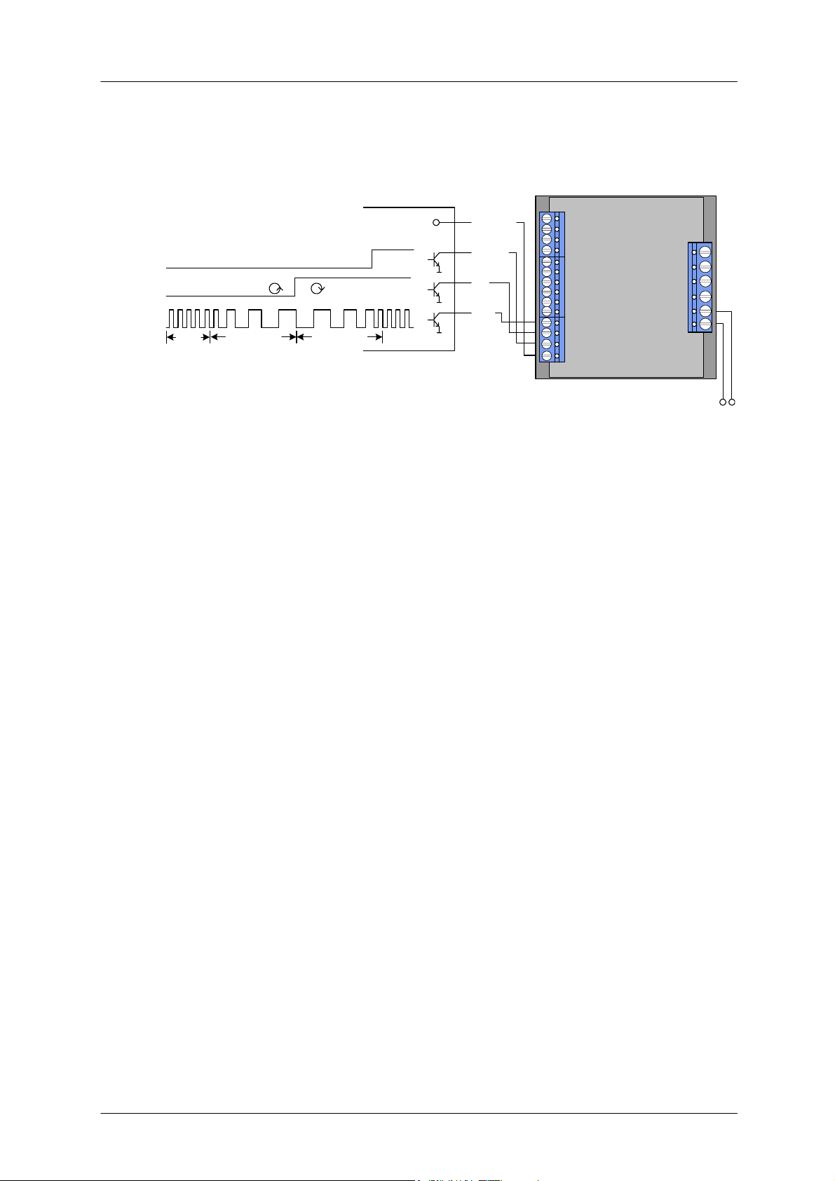
4.2 Step, Direction and Disable Inputs
The inputs disable, dir and step are electrically isolated from the module. The inputs are related to
V
. In a typical application, U
COM
inputs are driven by open collector or push / pull outputs. V
avoid reverse polarity for the opto couplers.
OFF: V
ON: V
- VIN < 1.0V
COM
- VIN >= 3.5V
COM
shall be tied to the positive supply voltage of the master and the
COM
OPTOFF
and V
must not exceed V
OPTON
COM
to
Examples:
U
COM
5..24V
Disable
Dir
Step
+5V
A
C
A
C
A
C
E
C
E
C
µC
A: Anode
C: Cathode
C: Collector
C
E
E: Emitter
GND
Figure 4.1: Step, Direction and Disable Inputs
V
= 5V
COM
V
OPTOFF
V
OPTOFF
20V19.0V16.5V
V
V
V
STEP
V
OPTON
= 0V 1.5V 4.0V 5V
STEP
= 20V
COM
V
OPTON
undefined
undefined
= 0V
Copyright © 2005, TRINAMIC Motion Control GmbH & Co. KG
Page 11

IDX Manual (V1.08 / August 30th, 2006) 11
5 Getting Started
5.1 Motor
Attention: Do not connect or disconnect the motor while power on. Damage to the module may occur.
Attention: A too high motor current setting can damage you motor! If in doubt, start with a low current
setting and check motor temperature. If the motor heats up very quickly, check all settings. The motor
shall never reach a temperature above 100°C under any circumstances. Some stepper motors need
contact to metallic parts to allow continuous operation. Mind the default settings, when you operate in
step / direction mode the first time! You can store your own settings in the module permanently.
5.1.1 Motor Choice
Care has to be taken concerning the selection of motor and supply voltage. In the different chopper
modes different criteria apply. Modes 0 and 1 are quite insensitive to the motor choice, while Mode 2
is very sensitive, because it uses a different motor current regulation scheme. This chapter gives
some mathematical information on the motor choice, but you can skip it if you want to experiment with
a given motor. Normally, best results will be achieved when operating the given motor in a range of 50
to 100% of nominal motor current (see motor data sheet). Mode 2 and mode 1 are mainly intended for
slow, smooth and very exact movements, due to the high microstepping resolution. For most dynamic
operation choose mode 0, or the combined modes 3 and 4 which use mode 1 or 2 for slow
movements and switch to mode 0 at a defined velocity.
5.1.1.1 Motor velocity
Whenever it is desired to maximize the motor velocity in a given application, it is important to
understand limitations due to supply voltage and motor inductivity. Please consult your motor data
sheet for this, as well as the choice of the chopper mode. Chopper mode 0 allows maximum motor
velocity.
5.1.1.2 Chopper Modes 0 (SPI / Default Mode) and 1 (PWM)
In these two modes the maximum supply voltage (VS) of the motor must not exceed 22-25 times the
nominal motor voltage (V
lead to an excess of motor rating.
The minimum supply voltage has to be above two times the nominal motor voltage.
), regarding the multiplication of I
N
V25...22VV2
⋅≤≤⋅
NSN
RIV
⋅=
MOTORMAX,COILN
COIL, MAX
and R
. A higher value would
MOTOR
Copyright © 2005, TRINAMIC Motion Control GmbH & Co. KG
Page 12

IDX Manual (V1.08 / August 30th, 2006) 12
5.1.1.3 Chopper Mode 2 (PHASE)
In Table 5.1 and Figure 5.1 examples of maximum power supply voltages regarding current I
inductivity of your motor are specified.
For further information, including a formula and description how to calculate the maximum voltage for
your setup, refer to 6.2.2.3
I
(RMS) L (min.) VS (max.)
COIL
456 mH 48 V
3.5 A
342 mH 36 V
228 mH 24 V
114 mH 12 V
533 mH 48 V
3.0 A
400 mH 36 V
266 mH 24 V
133 mH 12 V
800 mH 48 V
2.0 A
600 mH 36 V
400 mH 24 V
200 mH 12 V
1600 mH 48 V
1.0 A
1200 mH 36 V
800 mH 24 V
400 mH 12 V
3200 mH 48 V
0.5 A
2400 mH 36 V
1600 mH 24 V
800 mH 12 V
5333 mH 48 V
0.3 A
4000 mH 36 V
2666 mH 24 V
1333 mH 12 V
COIL
and
Table 5.1: Maximum voltage regarding motor current and inductivity
Copyright © 2005, TRINAMIC Motion Control GmbH & Co. KG
Page 13

IDX Manual (V1.08 / August 30th, 2006) 13
5000.0
4000.0
3000.0
L /mH
2000.0
1000.0
0.0
0.3 0.8 1.3 1.8 2.3 2.8 3.3
ICOIL /A
VS = 48V VS = 36V VS = 24V VS = 12V
Figure 5.1: Maximum voltage regarding motor current and inductivity
Any combination of motor coil current and inductivity which is above the curve for
maximum supply voltage (V
) is possible to drive the motor in this mode.
S
Check your motor data sheet, please.
1600.0
1400.0
1200.0
1000.0
800.0
L /mH
600.0
400.0
200.0
0.0
11.522.533.5
ICOIL /A
If in doubt, please start with a lower supply voltage and check motor heating when raising the voltage.
Copyright © 2005, TRINAMIC Motion Control GmbH & Co. KG
Page 14

IDX Manual (V1.08 / August 30th, 2006) 14
5.2 Connecting Motor and Power Supply
IDX
keep distance
short
Figure 5.2: Connecting Motor and Power Supply
C
Power supply
5.3 Power Supply Requirements
The power supply voltage shall be in the limits as given in the chapter 4 under operational ratings.
Please note that there is no protection against reverse polarity or too high voltage. The power supply
typically should be within a range which fits the motor requirements, as described in chapter 5.1.1.
When using supply voltages near the upper limit, a regulated power supply becomes a must. Please
ensure, that enough power filtering capacitors are provided in the system (1000µF for each ampere of
RMS motor current or more recommended), in order to absorb mechanical energy fed back by the
motor in stalling conditions. In larger systems a zener diode circuitry might be required, when motors
are operated at high velocities.
The power supply should be designed in a way, that it supplies the nominal motor voltage at the
desired maximum motor power. In no case shall the supply value exceed the upper / lower voltage
limit. To ensure reliable operation of the unit, the power supply has to have a sufficient output
capacitor and the supply cables should have a low resistance, so that the chopper operation does not
lead to an increased power supply ripple directly at the unit. Power supply ripple due to the chopper
operation should be kept at a maximum of a few 100mV.
Therefore we recommend to
a) keep power supply cables as short as possible
b) use large diameter for power supply cables
c) if the distance to the power supply is large (i.e. more than 2-3m), use a robust 4700µF (IDX
7505) or 2200µF (IDX 4803) or similar additional filtering capacitor located near to the motor
driver unit. Choose the capacitor voltage rating fitting to the maximum operating voltage.
The overall power rating mainly depends on the motor used and on the mechanical output power, i.e.
the motor velocity and desired torque. As a thumb rule, a 42mm class motor will require a 10W (short
motor) to 20W (long motor) power supply, while a 57mm motor will require 15W to 30W, when
operated at maximum rated current and low velocities. Operation at very high velocities will increase
the power demand up to the double value.
Copyright © 2005, TRINAMIC Motion Control GmbH & Co. KG
Page 15
IDX Manual (V1.08 / August 30th, 2006) 15
5.4 Connections for Step / Direction- Mode
The step-direction-mode is enabled if the acceleration is set to 0 (default) using the RS485 interface.
Common
Disable
Dir
Step
Disable
Dir
Step
Common
0 V
Common
0 V
Common
0 V
Velocity Deceleration Accel eration
rotating direction
const.
5 ... 24 V
rotation off on
GND
GND
GND
Figure 5.3: Contacts for Step-Direction
The maximum step frequency is 350 kHz (limited by the opto couplers).
TMCM-IDX
PWR 12...50 V
Copyright © 2005, TRINAMIC Motion Control GmbH & Co. KG
Page 16

IDX Manual (V1.08 / August 30th, 2006) 16
5.5 Connections for RS485 Interface
The RS485-mode allows for configuration of motor parameters as well as remote control of the motor.
5.5.1 Interface installation
To connect the module to a PC a RS485 interface is required, for example TRINAMIC’s new USB-2485 or any other RS485 adapter, like the standard RS232 to RS485-converters. Input A has to be
connected to RS485A of the IDX and Input B with RS485B.
Either use a RS232 to
Terminal
RS-232-port
USB-port
RS485 or alternatively
a USB to RS485 adapter
RS232toRS485
4 3 2 1
to
+ -
USB
RS485
alternative
-
+
-
+
TMCM-IDX
Figure 5.4: Contacts for RS485 with an adapter
5.5.2 Control with terminal program
Having installed the hardware, the IDX can be controlled with any terminal program, like
HyperTerminal that comes with MS-Windows. Following steps are described for HyperTerminal but
are similar for the other terminal programs:
1. Start HyperTerminal
2. A window for a new connection opens. Fill in a name and press OK.
3. Select the appropriate COM-port and press OK.
4. Fill in the values like in Figure 5.5 and confirm with OK.
Bit rate:
Data bits:
Parity:
Stop bits:
Flow control:
none
none
Figure 5.5 : Connection settings for RS485
Type into the terminal window commands like “AV 50000”, “AA 300” or “Ac” and execute each with
ENTER. Pay attention to the spaces between command and value. With standard RS485 adapters the
typed value may be echoed and lines like AAVV 5500000000 for the typed AV 50000 appear. If this
happens best is to pay no attention to the screen and just type in the commands and press ENTER.
The value sent to the module is only the typed and not the displayed. First command to the module
should be an acceleration differing from 0 to enable RS485 mode. If this value is stored to the
EEPROM step/direction control is not possible until acceleration is set to zero again (and eventually
stored) or the board is reset to factory default.
Copyright © 2005, TRINAMIC Motion Control GmbH & Co. KG
Page 17

IDX Manual (V1.08 / August 30th, 2006) 17
6 Functional Description
The IDX module has three different modes to control a stepper motor: step-direction, RS485 and
stand alone. With the RS485 it is possible to change parameters and save them to the EEPROM of
the module to have all options in any mode. Therefore there are different settings like microstep
resolution possible in step-direction mode also.
6.1 Disable Function
Description: The disable works as an emergency shutdown. Connected to ground all power to the
motor will shut down independent of the current settings.
It is in the users responsibility to stop the step impulses or set the velocity to zero before enabling the
motor again, because it would start abrupt otherwise.
Function Table:
V
open wire V
OPTON
motor disabled motor enabled
OPTOFF
6.2 RS485 Control Interface
The RS485 interface can control all functions of the IDX. It is possible to change parameters, with this
interface which are also valid in the other modes like max. velocity or acceleration. The parameters
can be written to the EEPROM to obtain the changes after a restart.
A Reset to factory default is possible. Default address byte is “A” and default baud rate is 9600 baud.
This mode can only be used with an appropriate RS485 interface. Commands are sent with a terminal
program, refer 5.5.
Copyright © 2005, TRINAMIC Motion Control GmbH & Co. KG
Page 18

IDX Manual (V1.08 / August 30th, 2006) 18
6.2.1 RS485 Commands
For RS485 commands write the address byte (default is A) first, followed by an command from the
following list. A small command letter provides the actual setting. All values are ASCII.
Command Function Description Range
A, a Acceleration Acceleration: v = 28.96 * a 0..2500000 0
C, c
E
G, g StallGuard
L, l Limit switch
M, m
O, o Set Output Output adjustments, Refer 6.2.1.6 2 bit 0
P Set Position Set position without moving the motor 32 bit
Q Read I/Os
R
S
T, t
U, u
V, v
W
X
Y, y
Z, z
Set Motor
Current
Failure
readout
Select
Mode
Read
Current
Position
Changes
address
byte
RS485Timeout
Set baud
rate
Velocity for
Rotation
Store
parameters
to EEPROM
Version
number
Standby
current
Microstep
Resolution
Motor current in percentage of maximum
current
(0..100% * IDX max. current). Refer 6.2.1.2
Provides failure readout. Refer 6.2.1.3
In mode 0 (SPI) the StallGuard feature is
functional. ‘g’ provides the actual StallGuard
value, not the setting. Refer 6.2.1.4
Used to switch on and off reference run
values. Refer 6.2.1.5
Select chopper mode: 0:SPI (default), 1:PWM,
2:PHASE, 3 & 4: Combinations, Refer 6.2.2
Provides out of the I/O the values of the ports
GPI, REF_A, REF_B, GPO and ALARM. Refer
6.2.1.7
Provides the current position of the motor 32 bit
Capital letter followed by the command ‘S’
makes this letter the new address byte
Sets the RS485-Timeout
Sets baud rate for RS485 communication.
Refer to 6.2.1.8
Velocity for rotation / reference run
v = n * 0.149157 usteps/s
Additional Parameter is 0 or missing: Carriage
Return (CR) comes after acceleration phase
Additional Parameter is 1: no delay of CR
Stores different parameters to the EEPROM to
restart with the same performance. Refer
6.2.1.9
Provides version number of implemented
Software
Sets 0..100% of maximum current after 1
second motor inactivity. For no standby current
use the same value as for “Set motor current”.
Sets the maximum microstep resolution (0:
max; 4: min), Refer 6.2.1.11
0..100 50
8 Bit (SPI)
1 Bit (others)
-7..0..+7 0
byte -
0, 1, 2, 3, 4 0
A
0…7 0
+/- 2500000,
0 or 1
0..100 20
0..4 0
Factory
Default
0
Table 6.1: RS485 Commands
Examples:
1. Set chopper mode to SPI Mode:
AM 0
⇒ ENTER
2. Read out the actual mode
Am
Copyright © 2005, TRINAMIC Motion Control GmbH & Co. KG
⇒ ENTER
Page 19

IDX Manual (V1.08 / August 30th, 2006) 19
6.2.1.1 Examples for test move
• Different accelerations and velocities
AA 500, AV 50000, AV –50000
⇒ try other AA 100…8000, AV 0…400000
• Max. current – test of torque
AA 500, AV 50000, AC 255
⇒ test torque manually ⇒ AC 50 ⇒ test torque
• Coil current change
AV 0, AA 500, AV 50000, AC 200, AI 0 (100%), AI 18 (50%), AI 45 (33%), AI 63 (25%)
AC 100, AI 0, AI 18, AI 45, AI 63
• Read and set position
AR, AP 0, AR, AA 500, AV 50000, AR
6.2.1.2 Motor Current (C)
The motor current can be set by the user. To do this use the RS485 command “AC” in addition with a
percent value. To calculate the actual setting, please use the 100% values as shown in the table.
Internally the current is regulated by two independent parameters for the best module/motor
performance possible.
For chopper mode 2, the maximum setting is about 75% to 90% - at higher settings, motor microstep
behaviour may become harsh. The actual maximum depends upon the actual motor. This is to avoid
the motor coil current raising above the 100% setting at any time. Not all currents can be continuously
driven at all supply voltages / cooling circumstances. Please refer to motor current limitations.
AC
100
75
66
50
33
25
10
I
COIL,PP
IDX 7505
7.1A 5.0A
5.3A 3.8A
4.7A 3.3A
3.5A 2.5A
2.4A 1.7A
1.8A 1.26A
0.71A 0.50A
I
COIL,RMS
IDX 7505
I
COIL,PP
IDX 4803
I
COIL,RMS
IDX 4803
% to max.
I
4.8A 3.4A 100% *)
3.6A 2.6A 75%
3.2A 2.2A 66%
2.4A 1.7A 50%
1.6A 1.1A 33%
1.2A 0.85A 25%
0.5A 0.35A 10%
COIL
Table 6.2: Motor Current Examples for IDX / IDX 4803
*) Not possible for chopper mode 2.
6.2.1.3 Failure Readout (E)
The IDX provides a full driver failure analysis in SPI mode (8 Bit). The returned bit assignments are as
follows:
Bit Name Function Remark
7 OT Overtemperature “1” = driver chip off due to overtemperature
6 OTPW temperature prewarning “1” = driver chip prewarning temperature exceeded
5 UV driver undervoltage “1” = undervoltage on VS – does not cover all cases
4 OCHS overcurrent high side (not available in current hardware implementation)
3 OLB open load bridge B Open load detection can occur at fast motion also.
2 OLA open load bridge B Open load detection can occur at fast motion also.
1 OCB overcurrent bridge B low side Short circuit detected. Please check motor wiring.
0 OCA overcurrent bridge A low side Short circuit detected. Please check motor wiring.
Table 6.3: Failure readout in SPI mode
In the other two modes the failure analysis consists of only one bit:
1: short circuit or overtemperature
0: no failure
Copyright © 2005, TRINAMIC Motion Control GmbH & Co. KG
Page 20

IDX Manual (V1.08 / August 30th, 2006) 20
6.2.1.4 StallGuard (G)
The StallGuard feature is available in the default mode 0 (SPI) only. It is a sensorless load
measurement and stall-detection. Overload is indicated before steps are lost. The command letter ‘g’
provides the actual StallGuard value of the motor so easy calibration is possible. To use StallGuard in
an actual application, some manual tests should be done first, because the StallGuard level depends
upon the motor velocities and on the occurrence of resonances. When switching on StallGuard, the
motor operation mode is changed and microstep resolution may be worse. Thus, StallGuard should be
switched off when not in use.
Value Description
-7..-1
0 StallGuard function is deactivated (default)
1..7 Motor stops when StallGuard value is reached and position is not set zero.
Motor stops when StallGuard value is reached and position is set zero
(useful for reference run).
Table 6.4: StallGuard
6.2.1.5 Limit Switch (L)
The parameter ‘L’ defines the different reference entrances of the module. The motor stops when the
defined position is reached.
Bit Motor stops at
0 REF_B = 0
1 REF_A = 0
2 GPI = 0
3 REF_B = 1
4 REF_A = 1
5 GPI = 1
6 0: soft stop, 1: hard stop
0: sets position zero
7
1: sets position not to zero
Table 6.5: Limit switch
To activate a reference switch set the appropriate bit to 1. When motor stops the position counter is
set to zero.
Example:
AL 8
⇒ ENTER : Activates REF_B = 1. When destination reached motor stops and position counter is
set to zero.
6.2.1.6 Output setting (O)
The bit settings are as follows:
Bit Description
0: GPO is inactive (LED off)
0
1: GPO is active (LED on)
1 1: Output is changed at end of reference run
Table 6.6: Output adjustment
Figure 6.1: GPO wiring scheme
Copyright © 2005, TRINAMIC Motion Control GmbH & Co. KG
Page 21

IDX Manual (V1.08 / August 30th, 2006) 21
=
6.2.1.7 I/Os Readout (Q)
Command:
⇒ ENTER
AQ
Bit
Port
7 6 5 4 3 2 1 0
0 0 0 GPI REF_B REF_A GPO ALARM
Table 6.7: I/Os Readout
6.2.1.8 Baud Rate (U)
The parameter ‘U’ changes the baud rate of the module for RS485 communication.
Parameter U Baud rate
0 9600 baud
1 14400 baud
2 19200 baud
3 28800 baud
4 38400 baud
5 57600 baud
6 76800 baud
7 115200 baud
Table 6.8: Baud rate
6.2.1.9 Velocity Mode (V)
The velocity mode allows rotation of the motor without external signals. In order to rotate the motor,
please set an acceleration value different from zero. The velocity is given by the following equation,
when parameter “AV n” is used:
⋅
⋅
]s/steps[v
For a 200 step motor at 64 microsteps, this gives
A practical limit with most stepper motor types is about 20 rotations / second in chopper mode 0 and 5
rotations / second in chopper mode 2.
As a second parameter, value “0” or “1” is optional. Standard is 0 and sends back the Carriage Return
character at once. If it is set to “1” sending back of the Carriage Return character is delayed until the
target velocity is reached.
Example:
AV –50000
AV 0 1
return until target velocity has been reached
⇒ ENTER: Accelerates motor to given velocity
⇒ ENTER: Accelerates motor to velocity zero (standstill) and delays echoing of carriage
=
]s/rotations[v
=
]s/rotations[v =
85815
149157.0n
resolutionMicrostep
149157.0n
⋅
n
]s/rotations[
]s/microsteps[149157.0n]s/microsteps[v
]s/steps[
⋅
motorofFullstepsresolutionMicrostep
]s/rotations[
Copyright © 2005, TRINAMIC Motion Control GmbH & Co. KG
Page 22
IDX Manual (V1.08 / August 30th, 2006) 22
6.2.1.10 Store Parameters to EEPROM (W)
This command stores the actual parameters to the EEPROM to restart with the same performance
after power down.
Stored parameters are:
• Current setting (C)
• Selected Mode (M)
• Output adjustment (O)
• RS485 parameters (U)
• Microstep resolution (Z)
6.2.1.11 Microstep Resolution (Z)
The microstep resolution can be set by the user. It depends on the maximum resolution witch differs in
the three different chopper modes (see 6.2.2).
The maximum resolution is set by the parameter ‘Z’.
Parameter Z
SPI PWM Phase (default)
0 max resolution 64 *) 64 256
1 1/2 max 32 *) 32 128
2 1/4 max 16 16 64
3 1/8 max 8 8 32
4 1/16 max 4 4 16
Microstep resolution
Table 6.9: Adjustment of Microstep Resolution
*) Simulated microsteps, the actual microsteps of the motor are not improved.
Example:
AZ 2
⇒ ENTER : Sets the microstep resolution to a quarter of the maximum resolution.
6.2.2 Chopper Modes
6.2.2.1 Chopper Mode 0 (SPI) / Default Mode
In this mode, the motor coil current is regulated on a chopper-cycle-by chopper-cycle bias. This is the
standard operation mode for most motor drivers. It brings a medium microstep resolution of 16
microsteps and typically works good with most motors and a high range of supply voltage and motor
current settings. A resolution of up to 64 microsteps can be simulated but the motor precision is not
improved compared to 16 microsteps.
The maximum supply voltage (V
voltage (V
), regarding the multiplication of I
N
excess of motor rating.
The minimum supply voltage has to be above two times the nominal motor voltage.
RIV
⋅=
It uses a chopper frequency of about 36kHz.
) of the motor must not exceed 22-25 times the nominal motor
S
COIL, MAX
V25...22VV2
⋅≤≤⋅
NSN
MOTORMAX,COILN
and R
. A higher value would lead to an
MOTOR
Copyright © 2005, TRINAMIC Motion Control GmbH & Co. KG
Page 23

IDX Manual (V1.08 / August 30th, 2006) 23
⋅
6.2.2.2 Chopper Mode 1 (PWM)
This mode is identical to the chopper mode 0 (SPI) mode, but it increases the microstep resolution at
low velocities / stand still.
V25...22VV2
⋅≤≤⋅
NSN
RIV
⋅=
MOTORMAX,COILN
6.2.2.3 Chopper Mode 2 (PHASE)
This mode uses a different chopper scheme, which provides a very high microstep resolution and
smooth motor operation. However motor dynamics and maximum velocity are quite limited. Care has
to be taken concerning the selection of motor and supply voltage:
The motor is chopped with 20kHz, and the coil sees a 50% duty cycle at full supply voltage when the
coil current is meant to be zero. This is only true for the average, but the motor still sees an alternating
current and thus an alternating magnetic field. Now, care has to be taken in order to keep this current
to a value which is significantly lower than the motor maximum coil current. If it is too high, the motor
has significant magnetization losses and coil power dissipation, and would get much too hot, even with
zero average current. The only possibility to limit this effect, is to operate with a comparatively low
supply voltage. The following calculation is based on the assumption that full motor current is set.
Check list:
Please take the motor inductivity L [mH] and motor rated full step coil current I
data sheet:
Now choose a supply voltage for the module to fulfil the following comparison:
s25V
µ⋅
S
L
COIL
5.0I
⋅≤
Ù
COILS
[]
mHL20IV
⋅≤
If your parameters do not fulfil the equation, i.e. you calculate a supply voltage which is below the
modules’ operation specs or which does not fit your system requirements, try the following:
Calculate x:
V
x
I
COIL
S
⋅=
025.0
[]
mHL
If x is below 0.5, everything is OK.
If x is in the range 0.5 to 1.0, try operating your motor and check if motor or driver gets too hot.
If x is above 1.0, choose one of the other chopper modes.
See also 5.1.1.3 for graphical demonstration.
[A] from the motor’s
COIL
Copyright © 2005, TRINAMIC Motion Control GmbH & Co. KG
Page 24

IDX Manual (V1.08 / August 30th, 2006) 24
6.2.2.4 Chopper mode 3 (Phase and SPI)
This mode combines the modes 2 (Phase) and 0 (SPI) in order to provide highest accuracy at lower
velocities and also the possibility for faster movements. Through the switching between modes some
microsteps may be lost. Microstep resolution must not be higher than 64. It is set according to Phase
mode, so possible values for Z (microstep resolution) are 2, 3 or 4.
µ-steps
V-value Rounds/s V-value Rounds/s
Phase to SPI SPI to Phase
64 192000 2.24 25000 0.29
32 96000 2.24 12500 0.29
16 48000 2.24 6250 0.29
Table 6.10: Chopper mode 3 switching velocities
Conversion of values above to motors with different fullstep resolutions:
motor
table
)s/rounds(v
200
)s/rounds(v
⋅=
revolutionperfullstepsmotors
6.2.2.5 Chopper mode 4 (PWM and SPI)
This mode combines the modes 1 (PWM) and 0 (SPI) in order to provide higher accuracy (up to 64
microsteps) at lower velocities and also the possibility for faster movements. For higher velocities in
SPI mode the microstep resolution is always 16, but set resolution is simulated. Through the switching
between modes some microsteps may be lost. Microstep resolution must not be higher than 64. It is
set according to Phase mode, so possible values for Z (microstep resolution) are 2, 3 or 4. This mode
should only be used in very special occasions and mode 3 should be preferred if a combination of high
accuracy at slow movements and high speed is needed.
Copyright © 2005, TRINAMIC Motion Control GmbH & Co. KG
Page 25

IDX Manual (V1.08 / August 30th, 2006) 25
6.3 Step / Direction
Additional Parameters can be set by RS485 i.e. to set a maximum velocity or microsteps per round.
The Step-Direction controls are as follows:
Motor Velocity Acceleration Rotate right Rotate left
Control
Disable
Direction
Step
Direction open
wired or connected
Step frequency
Increase of Step
frequency
Table 6.11: External signals and motor reactions
V
com
0 V
V
com
rotating direction
0 V
V
com
0 V
Velocity Deceleration Acceleration
const.
to V
COM
Direction
connected to
Ground
rotating on off
Speed
Motor
0
rotate right
rotate left
Figure 6.2: Step-Direction signals and motor reactions
6.3.1 Direction
Description: The Direction signal changes the motors rotation from clockwise (CW) to
counterclockwise (CCW) and
Function Table:
GND open wire V
motor CW motor CCW
vice versa.
= 5…24V
COM
Copyright © 2005, TRINAMIC Motion Control GmbH & Co. KG
Page 26
IDX Manual (V1.08 / August 30th, 2006) 26
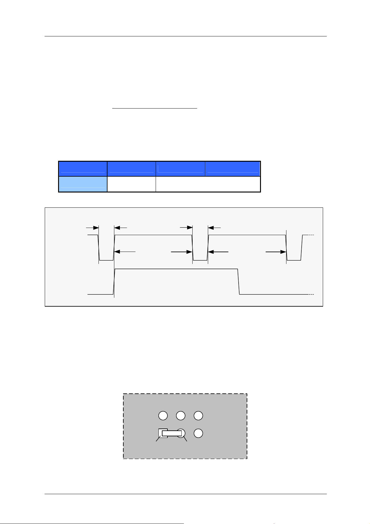
6.3.2 Step
Description: The Step signal adjusts the velocity and acceleration of the motor. The velocity is
depending on the frequency, the acceleration on the change of it. One step impulse represents one
microstep.
Calculation of rotations per second (refer to 6.2.1.11):
]s/rotations[v
=
Frequency: The maximum Step input frequency is 350 kHz, aligned to the Direction signal. The
minimum logic ”0” time is 0.7 µs and the minimum logic “1” time is 2.0 µs.
Maximum frequency at a duty cycle of 1 (“0” time is 2.0 µs and “1” time is 2.0 µs) is 250 kHz.
Function Table:
frequencyinputStep
⋅
resolutionMicrostepFullsteps
]s/rotations[
direction
Extern GND open wire V
Intern
0.7µs min
step pulse
HIGH LOW
2.0µs min
same minimum times as above
Figure 6.3: Step and Direction Signal
0.7µs min
= 5…24V
COM
2.0µs min
6.4 Reset to factory default
If the module seems to function weird this could usually is caused by unintended settings. In this case
a reset to factory default might be useful. To do this switch off the module and short-circuit pin 1 and
pin 3 of the free contacts for a 6-pin connector on the backside of the module. See Figure 6.4. Turn on
the module and switch it off again to remove the short-circuit. All settings are now at factory default.
pin 1
(quadratic)
Figure 6.4: Reset to factory default
Copyright © 2005, TRINAMIC Motion Control GmbH & Co. KG
pin 3
Page 27
IDX Manual (V1.08 / August 30th, 2006) 27
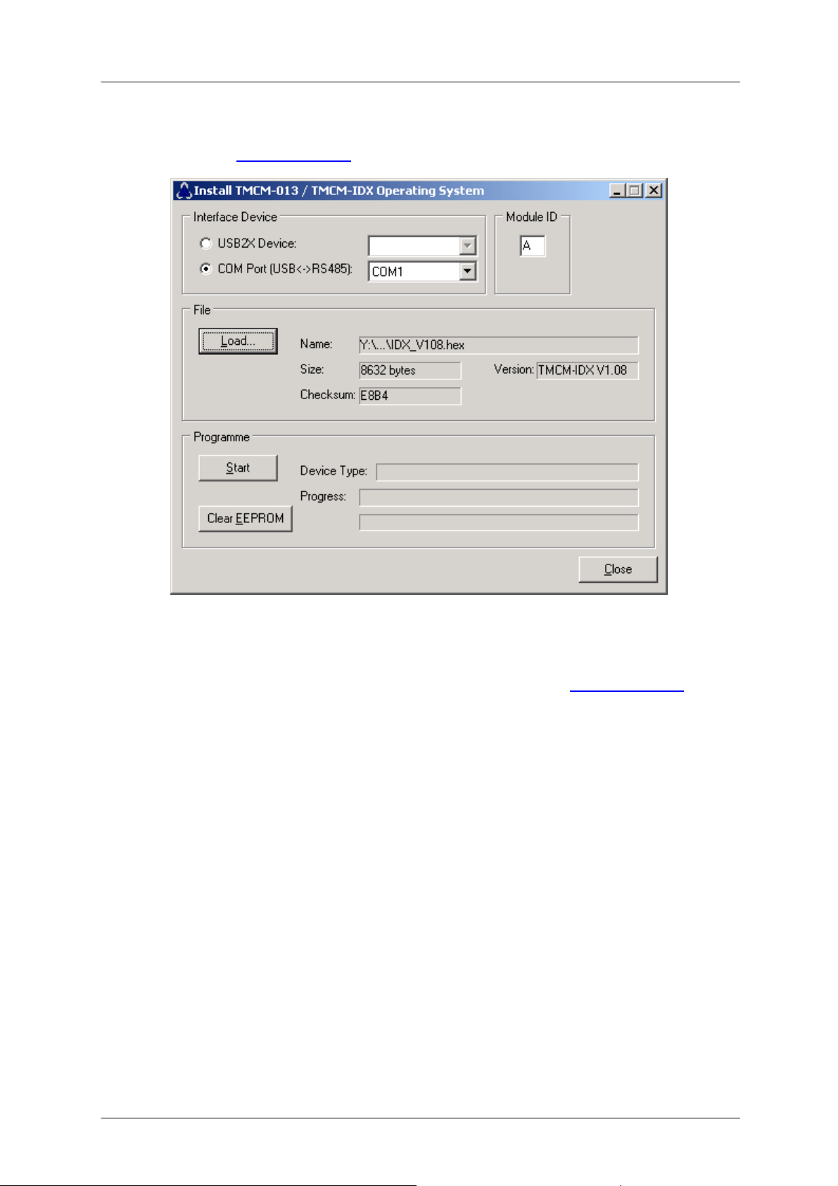
6.5 Firmware Update
For Firmware update start the program TMCM013boot.exe contained in the IDX-Folder of your
TMCTechLibCD or at www.trinamic.com:
Figure 6.5: Firmware update tool
1. Choose your RS485 connection.
2. Select your Module ID (default is A).
3. Load the new firmware file (e.g. IDX_V1.08.hex), to download from www.trinamic.com
4. Start the update process.
At the end of the update process check your firmware version with command “AX”.
.
Copyright © 2005, TRINAMIC Motion Control GmbH & Co. KG
Page 28

IDX Manual (V1.08 / August 30th, 2006) 28
6.6 Option: Pseudo DC-Motor mode (not supported by
software yet)
The velocity of the motor in this mode is
changed through a constant voltage at the
General Purpose input. The operational
voltage is 7...48V. This option may be
available in a future firmware version.
6.6.1 Setting up the module
It is advised to connect an external voltage
divider to the GPI pin, as depicted.
Figure 6.6: GPI wiring scheme
However, there are two free places for 0805 SMD resistors to be equipped directly on the module IDX.
To enable this mode solder use resistors as follows:
Attention: Do not try to make changes on the board until you are absolutely sure.
be absolutely sure before
making changes on board:
mounting hole
+V
S
7V...V
R = 120k
S
GPI
R = 2.2k
GND
T
IC
free Pads for 2.2k and 120k
Figure 6.7: Layout Changes for DC-Motor option
connector RM 3.5
T
IC
T
IC
DDD
ATM
168
6.6.2 Parameterizing with RS485
First set Parameters for minimum voltage, maximum voltage and a zero point in between. Other
values can be changed also like max. acceleration, max. velocity, microsteps,…
Before enabling this mode with the RS485 command … connect a voltage of 7…48V to General
Purpose Input (GPI). The voltage has to exceed zero point voltage before the regulation works.
6.6.3 Motion Control
Change the voltage at GPI between 7…48V. The motor will accelerate and decelerate relative to the
specified zero point. Additional parameters like resolutions of microsteps can be stored in the
EEPROM.
Copyright © 2005, TRINAMIC Motion Control GmbH & Co. KG
Page 29

IDX Manual (V1.08 / August 30th, 2006) 29
7 Revision History
7.1 Documentation Revision
Version Comment Description
1.00 First Release Full functionality for Firmware V1.05
1.01 Limit switch Added limit switch to documentation
1.02 Additions StallGuard added with RS485 command ‘G’, formerly used for output
setting (LED) now command ‘O’. Switched default mode to SPI.
1.04 Updates Added / modified some details
1.05 Updates RS485 connection documentation revised
1.06 Updates Corrected current default value, included IDX 7505 information
1.07 Updates Modes 3, 4 and GPO, GPI wiring scheme included
1.08 Updates Firmware update included
Table 7.1: Documentation Revisions
7.2 Firmware Revision
Version Comment Description
Pre 1.07 Please update
1.07 First Release Full functionality (except DC-Motor) with some possibilities to expand
1.08 Bug fix, new
options
Added chopper modes 3 and 4, modified V command, corrected RS485
bug (always echoing of CR at earlier versions)
Table 7.2: Firmware Revisions
Copyright © 2005, TRINAMIC Motion Control GmbH & Co. KG
 Loading...