

Page 1

MOPS/586
Technical Manual
Rev. 1.4
JUMPtec
Industrielle Computertechnik AG
Brunnwiesenstraße 16
94469 Deggendorf/ Germany
Tri-M Systems Inc., 6-1301 Ketch Court, Coquitlam, B.C., V3K 6X7, Canada
Phone: (604) 527-1100, (800) 665-5600 Fax: (604) 527-1110
Email: info@Tri-M.com Web: www.Tri-M.com
Page 2

MOPS/586 Table of Contents
Table of Contents
TABLE OF CONTENTS..........................................................................................................................................2
USER INFORMATION............................................................................................................................................4
T
RADEMARKS ............................................................................................................................................................4
G
ENERAL ..................................................................................................................................................................4
W
ARRANTY................................................................................................................................................................5
I
NTRODUCTION ..........................................................................................................................................................5
FEATURES .............................................................................................................................................................6
I/O MAP...................................................................................................................................................................7
MEMORY MAP FOR BIOS, SSD AND JRC SUPPORT........................................................................................8
ONBOARD SSD (DOS-COMPATIBLE) .................................................................................................................9
BLOCK DIAGRAM................................................................................................................................................10
CONNECTOR ARRANGEMENT..........................................................................................................................11
BIOS-DESCRIPTION............................................................................................................................................12
RTC-CMOS
AIN MENU.............................................................................................................................................................12
M
S
TANDARD CMOS SETUP........................................................................................................................................12
A
DVANCED CMOS SETUP .......................................................................................................................................14
P
OWER MANAGEMENT SETUP..................................................................................................................................16
P
ERIPHERAL SETUP.................................................................................................................................................17
UTO-DETECT HARD DISKS .....................................................................................................................................18
A
C
HANGE USER PASSWORD ......................................................................................................................................18
C
HANGE SUPERVISOR PASSWORD ...........................................................................................................................18
A
UTO CONFIGURATION WITH OPTIMAL SETTINGS.......................................................................................................18
A
UTO CONFIGURATION WITH FAIL SAFE SETTINGS ....................................................................................................18
S
AVE SETTINGS AND EXIT ........................................................................................................................................18
XIT WITHOUT SAVING.............................................................................................................................................18
E
AMIBIOS C
SETUP MENU .......................................................................................................................................12
ONFIGURATION SCREEN ........................................................................................................................19
HARDWARE DESCRIPTION................................................................................................................................20
HIPSET FEATURES ..........................................................................................................................................20
ALI-C
M
EMORY CONFIGURATION........................................................................................................................................20
I
NTERRUPTS............................................................................................................................................................21
DMA.......................................................................................................................................................................21
HE JIDA STANDARD ..............................................................................................................................................22
T
W
ATCHDOG EXTENSION...........................................................................................................................................25
NETWORK OPERATION......................................................................................................................................26
VERVIEW...............................................................................................................................................................26
O
SPECIFICATIONS ................................................................................................................................................27
M
ECHANICAL SPECIFICATIONS..................................................................................................................................27
E
LECTRICAL SPECIFICATIONS...................................................................................................................................27
E
NVIRONMENTAL SPECIFICATIONS............................................................................................................................27
PERIPHERAL INTERFACE..................................................................................................................................28
EYBOARD, RESET, BATTERY, SPEAKER..................................................................................................................28
K
ERIAL PORT COM 1, 2 (RS232C) .........................................................................................................................29
S
P
ARALLEL PORT LPT 1............................................................................................................................................30
Tri-M Systems Inc., 6-1301 Ketch Court, Coquitlam, B.C., V3K 6X7, Canada
Phone: (604) 527-1100, (800) 665-5600 Fax: (604) 527-1110
Email: info@Tri-M.com Web: www.Tri-M.com
Page 3

MOPS/586 Table of Contents
FLOPPY CONNECTOR...............................................................................................................................................30
IDE C
ONNECTOR FOR 2,5" HARD DISK.....................................................................................................................31
E
THERNET CONNECTOR...........................................................................................................................................31
F
EATURE CONNECTOR.............................................................................................................................................31
P
OWER CONNECTOR ...............................................................................................................................................32
PC/104-C
ONNECTOR ..............................................................................................................................................33
LITERATURE, STANDARDS, LINKS ..................................................................................................................34
PC/104-B
ISA-B
US...........................................................................................................................................................34
US, STANDARD PS/2 - CONNECTORS..............................................................................................................34
RS232C.................................................................................................................................................................34
DOCUMENT REVISION HISTORY ......................................................................................................................35
Tri-M Systems Inc., 6-1301 Ketch Court, Coquitlam, B.C., V3K 6X7, Canada
Phone: (604) 527-1100, (800) 665-5600 Fax: (604) 527-1110
Email: info@Tri-M.com Web: www.Tri-M.com
Page 4

MOPS/586 User Information
User Information
Copyright 1997 JUMPtec® Industrielle Computertechnik AG.
In this document JUMPtec
"JUMPtec
®
".
The information in this document has been carefully checked and is believed to be accurate and reliable.
However, no responsibility is assumed for inaccuracies. Furthermore, JUMPtec
changes to any portion of this manual to improve reliability, function or design. JUMPtec
®
Industrielle Computertechnik AG will also be referred to by the short form
®
reserves the right to make
®
does not assume any
liability for any product or circuit described herein.
Trademarks
AT and IBM are trademarks of International Business Machines
XT, AT, PS/2 and Personal System/2 are trademarks of International Business Machines Corporation.
Microsoft is a registered trademark of Microsoft Corporation.
Intel is a registered trademark of Intel Corporation.
All other products and trademarks mentioned in this manual are trademarks of their respective owners.
The reproduction, transmission or use of this document or its contents is not permitted without expressed written
authority.
Offenders will be liable for damages. All rights created by patent grant or registration of a utility model or
design, are reserved.
(C) JUMPtec
®
AG 1993
General
For the circuits, descriptions and tables indicated no responsibility is assumed as far as patents or other rights of
third parties are concerned.
The information in the Technical Descriptions describes the type of the boards and shall not be considered as
assured characteristics.
The reproduction, transmission or use of this document or its contents is not permitted without express written
authority. Offenders will be liable for damages. All rights, including rights created by patent grant or registration
of a utility model or design, are reserved.
Tri-M Systems Inc., 6-1301 Ketch Court, Coquitlam, B.C., V3K 6X7, Canada
Phone: (604) 527-1100, (800) 665-5600 Fax: (604) 527-1110
Email: info@Tri-M.com Web: www.Tri-M.com
Page 5

MOPS/586 User Information
Warranty
Each board is tested carefully and thoroughly before being shipped. If, however, problems should occur during
the operation, please check your user specific settings of all boards included in your system. This is often the
source of the fault. If a board is defective, it can be sent to your supplier for repair. Please take care of the
following steps:
1. The board returned should have the factory default settings since a test is only possible with these
settings.
2. In order to repair your board as fast as possible we require some additional information from you.
Please fill out the attached Repair Form and include it with the defective board.
3. If possible the board will be upgraded to the latest version without additional cost.
4. Upon receipt of the board please be aware that your user specific settings were changed during the
test.
Within the warranty period the repair is free of charge as long as the warranty conditions are observed. Because
of the high test expenditure you will be charged with the test cost if no fault is found. Repair after the warranty
period will be charged.
This JUMPtec
the date of shipment. During the warranty period JUMPtec
®
product is warranted against defects in material and workmanship for the warranty period from
®
will at its option either repair or replace defective
products.
For warranty service or repair the product must be returned to a service facility designated by JUMPtec
®
.
The foregoing warranty shall not apply to defects resulting from improper or inadequate maintenance or
handling by buyer, unauthorized modification or misuse, operation outside of the product´s environmental
specifications or improper installation or maintenance.
JUMPtec
are caused by a faulty JUMPtec
®
will not be responsible for any defects or damages to other products not supplied by JUMPtec® that
®
product.
Introduction
The MOPS/586 integrates the complete functionality of an 80486 motherboard with CPU, System-BIOS, 8
Mbyte to 32 MByte DRAM, keyboard-controller, real time clock and additional peripheral functions like COM1,
COM2, LPT1, Floppy-interface, EIDE-harddisk-interface, watchdog and optional Ethernet access. The system
runs with CPU clock speed 133MHz.
Tri-M Systems Inc., 6-1301 Ketch Court, Coquitlam, B.C., V3K 6X7, Canada
Phone: (604) 527-1100, (800) 665-5600 Fax: (604) 527-1110
Email: info@Tri-M.com Web: www.Tri-M.com
Page 6

MOPS/586 Features
Features
• Processor
®
AMD Am5x86
• Chipset
ALI 1489/1487 PCI Chipset
• Power Supply
5V only supply
• Memory
4 MB onboard and 4/8/16/32MB 5V-DIMM module DRAM with Fast Page Mode or
EDO DRAM on the lower SO-DIMM-Connector
• Ethernet 10BaseT (Twisted Pair)
with 133 MHz internal Clock and 16 kByte write-back-Cache
• Two serial ports, (COM1 and COM2)
standard RS232C serial ports with FIFO, 16550 compatible
• Parallel port, LPT1
With ECP/EPP-support
• Floppy-interface
• EIDE-PCI-hard disk-interface
PCI Bus Master IDE port (up to 2 IDE Devices)
supports PIO Mode 3,4 IDE & ATAPI CD-ROM
supports JUMPtec CHIPdisk
• Watchdog
• 128 KByte FLASH-BIOS (AMI) and 1,6 Mbyte onboard SSD (DOS-compatible)
• Real Time Clock
With external Battery-support
• Keyboard Controller
Tri-M Systems Inc., 6-1301 Ketch Court, Coquitlam, B.C., V3K 6X7, Canada
Phone: (604) 527-1100, (800) 665-5600 Fax: (604) 527-1110
Email: info@Tri-M.com Web: www.Tri-M.com
Page 7

MOPS/586 I/O Map
I/O Map
The I/O-port addresses of the processor module MOPS/586 are functionally identical with a standard PC/AT.
I/O Addresses MOPS/586 - onboard Function
0000 - 001F X DMA-Controller 1
0020 - 003F X Interrupt-Controller 1
0040 - 0043 X Timer
0050 - 005F Onboard Control Registers
0060 - 0064 X Keyboard-controller
0061 X Port B Register
0070 X NMI Enable Register
0070 - 0071 X Real Time Clock
0080 - 008F X DMA Page Register 74LS612
0092 X Port A Register (Fast A20 Gate)
00A0 - 00BF X Interrupt-Controller 2
00C0 - 00DF X DMA-Controller 2
00F0 - 00FF X Math-Coprocessor
0100 – 10F X Onboard Control Registers
01F0 - 01F8 X Fixed Disk
0200 – 0207 Game I/O
020C-020D Reserved
021F Reserved
0274 Control Register 1 External SSD (Board 0 - 3)
0275 Control Register 1 External SSD (Board 4 - 7)
0278 – 027F Parallel Port 2
02B0 - 02DF Alternate Enhanced Graphics Adapter
02E1 GPIB (adapter 0)
02E2 - 02E3 Data acquisition (Adapter 0)
02E8 - 02EF Serial Port 4
02F8 - 02FF X Serial Port 2
0300 – 030F X Onboard Network (default configuration)
0310 – 031F Prototype Card
0360 – 0363 PC Network (low Address)
0364 – 0367 Reserved
0368 – 036B PC Network (high Address)
036C – 036F Reserved
0370 – 0377 Config. Space for second SMC Controller
0378 – 037F X Parallel Port 1
0380 – 038F SDLC, Bisynchronous 2
0390 – 0393 Cluster
03A0 - 03AF Bisynchronous 1
03B0 - 03BF Monochrom Disp. and Printer Adap.
03C0 - 03CF Enhanced Graphic Adapter
03D0 - 03DF Color/Graphic Monitor Adapter
03E8 - 03EF Serial Port 3
03F0 - 03F7 X Diskette Controller
03F8 - 03FF X Serial Port 1
Tri-M Systems Inc., 6-1301 Ketch Court, Coquitlam, B.C., V3K 6X7, Canada
Phone: (604) 527-1100, (800) 665-5600 Fax: (604) 527-1110
Email: info@Tri-M.com Web: www.Tri-M.com
Page 8

MOPS/586 Memory Map for BIOS, SSD and JRC Support
Memory Map for BIOS, SSD and JRC Support
The BIOS includes two special extensions to support the onboard silicon state disk and Jumptec Remote Control.
If the SSD is enabled in setup or the JRC client finds a host the code of the bios extension will be copied into
shadow ram. The location where the biosextension is placed is automatically determined by the system bios .
The user can not influence this! So care must be taken, when a Extended Memory Manager is used. To avoid
memory conflicts exclude the area E0000h-EFFFFh and do’nt include the area C0000h-DFFFFh !
DOS allows to address 1MByte directly. The memory area above 1MByte (high memory, extended memory) is
accessed under DOS via special drivers like HIMEM.SYS, EMM386.EXE etc. Other operating systems (OS/2,
Windows-NT) allow to address the full memory area directly.
Standard Memory Map
000000h +-------------------+ ¦ Interruptvectors ¦ ¦ 640KByte
¦ BIOS-variables ¦ ¦ of
¦ IO.SYS, MSDOS.SYS ¦ ¦ main memory
¦ COMMAND.COM ¦ ¦
¦ Applications ¦ ¦
0A0000h +-------------------¦ +
¦ EGA/VGA Video- ¦ ¦
¦ Adapter ¦ ¦ upper memory
0B0000h +-------------------¦ ¦ area
¦ MGA/CGA Video- ¦ ¦ (RAM areas not
¦ Adapter ¦ ¦ used by video
0C0000h +-------------------¦ ¦ cards can be ¦ VGA BIOS ¦ ¦ used otherwise) ¦ 48KByte
0CC000h +-------------------¦ ¦ ¦ Shadow RAM
¦ BIOS-extensions ¦ ¦ (all not used ¦ Shadow-RAM ¦ ¦ areas could be
¦ Dual port RAM ¦ ¦ used otherwise)
¦ etc. ¦ ¦
0E0000h +-------------------¦ ¦ ¦ System-Setup ¦ ¦ ¦ 128KByte
¦ System-BIOS ¦ ¦ ¦ Shadow RAM
100000h +-------------------¦ + ¦ ¦ ¦ higher memory area
110000h +-------------------¦ +
¦ ¦ ¦ extended or
¦ ¦ ¦ expanded memory
+-------------------+
Tri-M Systems Inc., 6-1301 Ketch Court, Coquitlam, B.C., V3K 6X7, Canada
Phone: (604) 527-1100, (800) 665-5600 Fax: (604) 527-1110
Email: info@Tri-M.com Web: www.Tri-M.com
Page 9

MOPS/586 Onboard SSD (DOS-compatible)
Expanded Memory Map
The user can convert (up to 20Mbytes) Extended Memory into Expanded Memory (EMS). The selected
Expanded Memory is devided into 16KByte pages, of which four can be mapped into the EMS-frame. The EMSframe is located within the first 1MByte address space and has a length of 64KByte. The start address of the
EMS-page can be selected between CC000h and E0000h in steps of 16KBytes. Most Expanded Memory
Managers are choosing their frame address location by themselves if it is not explicit set..
000000h +-------------------+ ¦ Interruptvectors ¦ ¦ 640KByte
¦ BIOS-variables ¦ ¦ of
¦ IO.SYS, MSDOS.SYS ¦ ¦ main memory
¦ COMMAND.COM ¦ ¦
¦ HIMEM, EMM386 ¦ ¦
¦ Applications ¦ ¦
0A0000h +-------------------¦ +
¦ EGA/VGA Video- ¦ ¦
¦ Adapter ¦ ¦ upper memory
0B0000h +-------------------¦ ¦ area
¦ MGA/CGA Video- ¦ ¦ (RAM areas not
¦ Adapter ¦ ¦ used by video
0C0000h +-------------------¦ ¦ cards can be ¦ VGA BIOS ¦ ¦ used otherwise) ¦ 48KByte
0CC000h +-------------------¦ ¦ ¦ Shadow RAM
¦ BIOS-extensions ¦ ¦ (all not used ¦ Shadow-RAM ¦ ¦ areas could be
¦ Dual port RAM ¦ ¦ used otherwise)
¦ EMS-Pages ¦ ¦
¦ etc. ¦ ¦
0E0000h +-------------------¦ ¦ ¦ System-Setup ¦ ¦ ¦ 128KByte
¦ System-BIOS ¦ ¦ ¦ Shadow RAM
100000h +-------------------¦ + ¦ ¦ ¦ higher memory area
110000h +-------------------¦ +
¦ ¦ ¦ extended or
¦ ¦ ¦ expanded memory
+-------------------+
To be able to work with Expanded Memory under MS-DOS, you have to add the following drivers to your
CONFIG.SYS:
HIMEM.SYS and EMM386.EXE
The MOPS/586 uses a 32KByte extension BIOS (many other boards do this, too) which is mapped to a
configurable memory area. Some other kind of boards have no extension BIOS, but are using drivers which
communicate with their corresponding devices via memory mapped I/O. All these boards have one thing in
common, they have to share the upper memory area with the Expanded Memory Manager. This is often the
reason for several problems in the system. Make sure you excluded all areas in the upper memory, which are
used by extension BIOSes and memory mapped I/O. Your instruction in the CONFIG.SYS concerning the
Expanded Memory Manager should look like this: (questionmarks for location of extension BIOS)
DEVICE=EMM386.EXE X=E000-EFFF
Onboard SSD (DOS-compatible)
The onboard Solid State Disk (SSD) won’t work under any protected mode operating system, like WINDOWS
3.1, WINDOWS FOR WORKGROUPS 3.11, WINDOWS NT, OS/2 etc.
For SSD-Setup look to Fehler! Verweisquelle konnte nicht gefunden werden. on page Fehler! Textmarke
nicht definiert..
Tri-M Systems Inc., 6-1301 Ketch Court, Coquitlam, B.C., V3K 6X7, Canada
Phone: (604) 527-1100, (800) 665-5600 Fax: (604) 527-1110
Email: info@Tri-M.com Web: www.Tri-M.com
Page 10
MOPS/586 Block Diagram
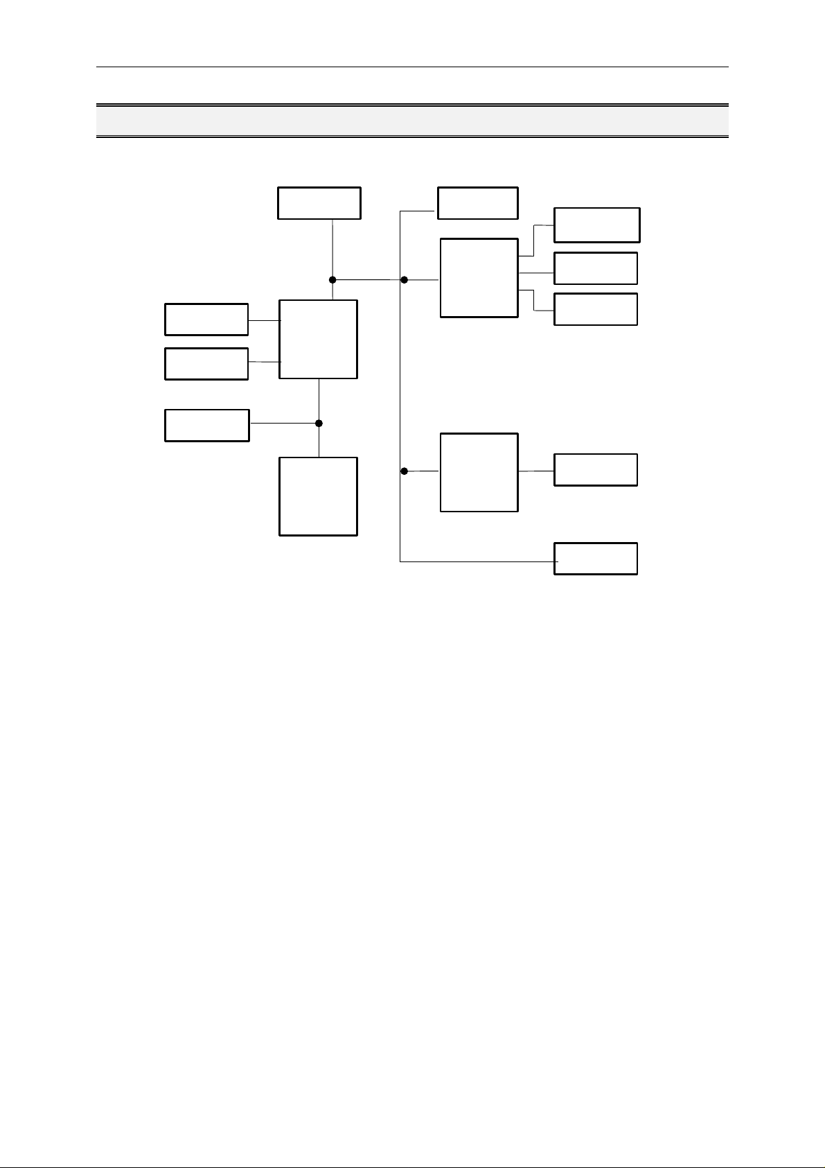
Block Diagram
EIDE
DRAM
Cache
BIOS
ALI
Chipset
CPU
RTC
IO-Con-
troller
Ethernet-
Con-
troller
LPT1
COM1
COM2
10baseT
ISA-Con.
Tri-M Systems Inc., 6-1301 Ketch Court, Coquitlam, B.C., V3K 6X7, Canada
Phone: (604) 527-1100, (800) 665-5600 Fax: (604) 527-1110
Email: info@Tri-M.com Web: www.Tri-M.com
Page 11
MOPS/586 Connector Arrangement
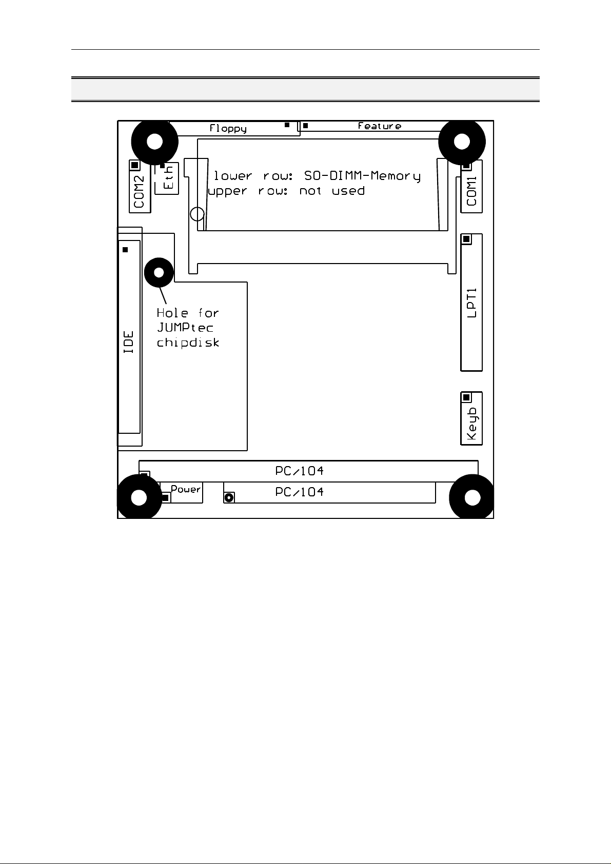
Connector Arrangement
Tri-M Systems Inc., 6-1301 Ketch Court, Coquitlam, B.C., V3K 6X7, Canada
Phone: (604) 527-1100, (800) 665-5600 Fax: (604) 527-1110
Email: info@Tri-M.com Web: www.Tri-M.com
Page 12

MOPS/586 BIOS-Description
BIOS-Description
The Standard AMI-BIOS is located in the Flash EPROM onboard. This device has 8 bit wide access. 16 bit
access is enabled by the shadow RAM feature (Standard).
RTC-CMOS setup menu
During boot sequence the CMOS setup can be entered by pressing the <DEL>-key while the memory test is in
progress.
Main Menu
• Standard CMOS Setup
• Advanced CMOS Setup
• Power Management Setup
• Peripheral Setup
• Auto-Detect Hard Disks
• Change User Password
• Change Supervisor Password
• Auto Configuration with Optimal Settings
• Auto Configuration with Fail Safe Settings
• Save Settings and Exit
• Exit Without Saving
Standard CMOS Setup
Date/Time
Select the Date/Time option to change the date or time. The current date and time are displayed.
Floppy Drive A, B
Choose the Floppy Drive A or B to specify the floppy drive type. The settings are Not Installed, 360 KB
5¼”, 1.2 MB 5¼”, 720 KB 3½”, 1.44 MB 3½”, or 2.88 MB 3½”.
Pri Master, Pri Slave, Sec Master, Sec Slave
Enter the correct settings for the attached mass storage drive. Possible settings are Not Installed, 1-46
(predefined types), User, AUTO, CDROM.
Configuring an MFM Drive: If configuring an old MFM hard disk drive, you must know the drive
parameters (number of heads, number of cylinders, number of sectors, the starting write
precompensation cylinder, and drive capacity). Choose Type and choose the appropriate hard disk
drive type (1 - 46). The old MFM hard drive types are listed on page 13. If the drive parameters of your
MFM drive do not match any drive type listed on page 13, select User in the Type field and enter the
drive parameters on the screen that appears.
User-Defined Drive: If you are configuring a SCSI drive or an MFM, RLL, ARLL, or ESDI drive with
drive parameters that do not match drive types 1-46, you can select the User in the Type field. You
must then enter the drive parameters on the screen that appears. The drive parameters include:
• Size (drive capacity, calculated automatically)
• Cyln (number of cylinders),
• Head (number of heads),
Tri-M Systems Inc., 6-1301 Ketch Court, Coquitlam, B.C., V3K 6X7, Canada
Phone: (604) 527-1100, (800) 665-5600 Fax: (604) 527-1110
Email: info@Tri-M.com Web: www.Tri-M.com
Page 13

MOPS/586 BIOS-Description
• WPcom (starting write precompensation cylinder)
• Sec (number of sectors)
Parameter Description
Type The number for a drive with certain identification parameters.
Cylinders The number of cylinders in the disk drive.
Heads The number of heads.
Write
Precompensation
The size of a sector gets progressively smaller as the track diameter diminishes. Yet each sector must still hold 512
bytes. Write precompensation circuitry on the hard disk compensates for the physical difference in sector size by
boosting the write current for sectors on inner tracks. This parameter is the track number where write
precompensation begins.
Landing Zone This number is the cylinder location where the heads will normally park when the system is shut down.
Sectors The number of sectors per track. MFM drives have 17 sectors per track. RLL drives have 26 sectors per track. ESDI
Size The formatted capacity of the drive is (Number of heads) x (Number of cylinders) x (Number of sectors per track) x
drives have 34 sectors per track. SCSI and IDE drives have more sectors per track.
(512 bytes per sector)
Configuring IDE Drives: If the hard disk drive to be configured is an IDE drive, select the option
AUTO and press <ENTER> to detect all drive parameters automatically.
AMIBIOS automatically detects the IDE drive parameters (including ATAPI CD-ROM drives) and
displays them. You can set the parameters manually if you are absolutely certain that you know the
correct IDE drive parameters.
Set LBA Mode to On to enable support for IDE drives with capacities greater than 528 MB.
Set Blk Mode to On to support IDE drives that use Block Mode.
Choose PIO Mode to select the IDE Programmed I/O mode. PIO programming also works with ATAPI
CD-ROM drives. The settings are Auto, 0, 1, 2, 3, 4, or 5. Use Auto to allow AMIBIOS to automatically
find the PIO mode that the IDE drive being configured uses. If you select 0-5 you must make
absolutely certain that you are selecting the PIO mode supported by the IDE drive being configured.
Set 32Bit Mode to On to support IDE drives that permit 32-bit accesses.
Configuring a CD-ROM Drive: Select the appropriate drive (Pri Master, Pri Slave, Sec Master, or Sec
Slave). Choose the Type parameter and select CDROM. You can boot the computer from a CD-ROM
drive. You can also choose Auto and let AMIBIOS automatically set the correct drive parameters.
Hard Disk Drive Types
Please look for Setup-Screen.
Boot Sector Virus Protection
If enabled, any write access to the hard disks boot sector will be trapped and reported on the screen.
The user himself decides if the access accomplishes. The Optimal and Fail Safe default settings are
Disabled.
Tri-M Systems Inc., 6-1301 Ketch Court, Coquitlam, B.C., V3K 6X7, Canada
Phone: (604) 527-1100, (800) 665-5600 Fax: (604) 527-1110
Email: info@Tri-M.com Web: www.Tri-M.com
Page 14

MOPS/586 BIOS-Description
Advanced CMOS Setup
Quick Boot
Set this option to Enabled to instruct AMIBIOS to boot quickly when the computer is powered on. This
option replaces the former Above 1 MB Memory Test Advanced Setup option. The settings are:
Setting Description
Disabled AMIBIOS tests all system memory. AMIBIOS waits up to 40 seconds for a READY signal from the IDE hard disk drive.
AMIBIOS waits for 0.5 seconds after sending a RESET signal to the IDE drive to allow the IDE drive time to get ready again.
AMIBIOS checks for a <DEL> key press and runs Setup if the key has been pressed.
Enabled AMIBIOS does not test system memory above 1 MB.
AMIBIOS does not wait up to 40 seconds for a READY signal from the IDE hard disk drive. If a READY signal is not
received immediately from the IDE drive, AMIBIOS does not configure that drive. AMIBIOS does not wait for 0.5 seconds
after sending a RESET signal to the IDE drive to allow the IDE drive time to get ready again.
The Optimal default setting is Enabled. The Fail Safe default setting is Disabled.
BootUp Sequence
Choose the type of the boot device and the order to boot from. Possible settings are „C:,A:,CDROM“,
„A:, C:, CDROM“ and „CDROM, A:, C:“.
BootUp Num-Lock
Set this option to Off to turn the Num Lock key off when the computer is booted so you can use the
arrow keys on both the numeric keypad and the keyboard. The settings are On or Off. The Optimal
and Fail Safe default settings are On.
Floppy Drive Swap
Set this option to Enabled to permit drives A: and B: to be swapped. The settings are Enabled or
Disabled. The Optimal and Fail Safe default settings are Disabled.
System Keyboard
This option specifies that a keyboard is attached to the computer. The settings are Present or Absent.
The Optimal and Fail Safe default settings are Absent.
Primary Display
This option specifies the type of display monitor and adapter in the computer. The settings are Mono,
CGA40x25, CGA80x25, VGA/EGA, or Absent. The Optimal and Fail Safe default settings are Absent.
Password Check
This option enables password checking every time the computer is powered on or every time Setup is
executed. If Always is chosen, a user password prompt appears every time the computer is turned on.
If Setup is chosen, the password prompt appears if Setup is executed. The Optimal and Fail Safe
default settings are Setup.
OS/2 Compatible Mode
Set this option to Enabled to permit AMIBIOS to run with IBM OS/2. This in only necessary if more
than 64MB of system dram is present. The settings are Enabled or Disabled. The Optimal and Fail
Safe default settings are Disabled.
Tri-M Systems Inc., 6-1301 Ketch Court, Coquitlam, B.C., V3K 6X7, Canada
Phone: (604) 527-1100, (800) 665-5600 Fax: (604) 527-1110
Email: info@Tri-M.com Web: www.Tri-M.com
Page 15

MOPS/586 BIOS-Description
Wait For 'F1' if Error
If this option is Enabled the system will wait on power up for the user to press the <F1> key on any
occurring error. The Optimal and Fail Safe default settings are Disabled.
Hit ‚Del‘ Message Display
If this option is Enabled the system will display the String „Hit DEL if you want to run Setup“ on the
screen while accepting the DEL key to enter setup. If the option is set to Disabled the string want be
displayed.
Internal Cache
This option specifies the caching algorithm used for L1 internal cache memory. The settings are:
Setting Description
Disabled The L1 internal cache memory on the CPU is disabled
WriteBack
Use the write-back caching algorithm
(Optimal and Fail
Save default)
Shadow Region Cacheability
When this option is set to Enabled, the contents of the shadow region can be read from or written to
cache memory. System BIOS, Video BIOS and Biosextensions are mostly copied from the BIOS ROM
to system RAM for faster execution. The settings are Enabled or Disabled. The Optimal default setting
is Enabled. The Fail Safe default setting is Disabled.
C000,16k Shadow, C400,16k Shadow, C800,16K Shadow, CC00,16K Shadow, D000,16K
Shadow; D400,16K Shadow; D800,16K Shadow; DC00, 16K Shadow
These options control the location of the contents of the 16KB of ROM beginning at the specified
memory location. If no adaptor ROM is using the named ROM area, this area is made available to the
local bus. The settings are:
Setting Description
Disabled The ROM is not copied to RAM. The contents of the
Enabled The ROM contents are written to the same address in
ROM cannot be read from or written to cache memory
system memory (RAM) for faster execution
NOTE: If an onboard video controller is present (MOPSlcd4), the BIOS automatically copies the
video bios into shadow ram blocks C000, C400 and C800. In that case these options are
grayed and not accessible in setup!
Watchdog Mode
With these settings, the type of watchdog is specified. Possible settings are Disabled, Reset, NMI. The
Optimal and Fail Safe default settings are Disabled.
Watchdog Delay (available only if Watchdog Mode is not Disabled)
Time delay before the watchdog timer is set. Used for example, to let the system boot without the
need to trigger the watchdog. Possible time settings are 1 Sec, 5 Sec, 10 Sec, 30 Sec, 1 Min, 5 Min,
10 Min, 30 Min.
Watchdog Timeout (available only if Watchdog Mode is not Disabled)
The watchdog must be triggered (reset) within this span of time. Possible time settings are 0.4 Sec, 1
Sec, 5 Sec, 10 Sec, 30 Sec, 1 Min, 5 Min, 10 Min.
Tri-M Systems Inc., 6-1301 Ketch Court, Coquitlam, B.C., V3K 6X7, Canada
Phone: (604) 527-1100, (800) 665-5600 Fax: (604) 527-1110
Email: info@Tri-M.com Web: www.Tri-M.com
Page 16

MOPS/586 BIOS-Description
Power Management Setup
Power Management/APM
If this option is Disabled, none of the below listed options are available, the system doesn't provide
you with power save features. The Optimal and Fail Safe default settings are Disabled.
Instant On Support
Instant On is a Power Managment Software for Windows 95. Must be Enabled to support this
Software. The Optimal and Fail Safe default settings are Disabled.
Green PC Monitor Power State
This option specifies the power management state that the Green PC-compliant video monitor enters
after the specified period of display inactivity has expired. The settings are Stand By, Suspend, Off.
Video Power Down Mode
This option specifies the power management state that the video subsystem enters after the specified
period of display inactivity has expired. The settings are Disabled, Standby, or Suspend.
Hard Disk Power Down Mode
This option specifies the power management state that the hard disk drive enters after the specified
period of HDD inactivity has expired. The settings are Disabled, Standby, or Suspend.
Hard Disk Time Out (Minute)
After this period, the hard disk drive is entering its power down mode. Possible settings are Disabled,
1, 2, 3, 4, 5....14.
Standby Time Out (Minute)
After this period, the specified devices are entering the standby mode. In Standby mode, some power
use is curtailed. Possible settings are Disabled, 1, 2, 3, 4, 5....14.
Suspend Time Out (Minute)
After this period, the specified devices are entering the suspend mode. In Suspend mode, nearly all
power use is curtailed. Possible settings are Disabled, 1, 2, 3, 4, 5....14.
Display Activity, IRQ3, IRQ4, IRQ5, IRQ7, IRQ9, IRQ10, IRQ11, IRQ12, IRQ13, IRQ14, IRQ15
These options enable event monitoring. When the computer is in a power saving mode, activity on the
named interrupt request line is monitored by AMIBIOS. When any activity occurs, the computer enters
Full On mode. Each of these options can be set to Monitor or Ignore. The Fail Safe default setting is
Ignore.
Tri-M Systems Inc., 6-1301 Ketch Court, Coquitlam, B.C., V3K 6X7, Canada
Phone: (604) 527-1100, (800) 665-5600 Fax: (604) 527-1110
Email: info@Tri-M.com Web: www.Tri-M.com
Page 17

MOPS/586 BIOS-Description
Peripheral Setup
Onboard IDE
This option enables the onboard IDE controller. The settings are Disabled and Enabled. The Optimal
and Fail Safe default settings are Enabled.
Onboard FDC
This option enables the floppy drive controller on the motherboard. The settings are Enabled or
Disabled. The Optimal and Fail Safe default settings are Enabled.
Onboard Serial Port1
This option enables serial port 1 on the motherboard and specifies the base I/O port address for serial
port 1. The settings are Disabled, 3F8, 2F8, 3E8,2F8. The Optimal and Fail Safe default settings are
3F8.
Onboard Serial Port2
This option enables serial port 2 on the motherboard and specifies the base I/O port address for serial
port 2. The settings are Disabled, 3F8, 2F8, 3E8,2F8. The Optimal and Fail Safe default settings are
2F8.
Onboard Parallel Port
This option enables the parallel port on the motherboard and specifies the parallel port base I/O port
address. The settings are Disabled, 378, 278, 3BC. The Optimal and Fail Safe default settings are
378.
Parallel Port Mode
This option specifies the parallel port mode. EPP and ECP are bidirectional data transfer schemes that
adhere to the IEEE P1284 specifications. The settings are:
Setting Description
Normal The normal parallel port mode is used. This is the default
BI-DIR The bidirectional parallel port mode is used.
setting.
EPP 1.7 The parallel port can be used with devices that adhere to the
Enhanced Parallel Port (EPP) specification version 1.7. EPP
uses the existing parallel port signals to provide asymmetric
bidirectional data transfer driven by the host device.
EPP 1.9 The parallel port can be used with devices that adhere to the
ECP The parallel port can be used with devices that adhere to the
Enhanced Parallel Port (EPP) specification version 1.9.
Enhanced Capabilities Port (ECP) specification.
Parallel Port IRQ (available only if Onboard Parallel Port is not set to Auto)
This option specifies the IRQ line for the parallel port. The settings are 5, 7. The Optimal and Fail Safe
default settings are 7.
Note: If Parallel Port Mode is ECP DMA channel 3 is used!
SSD INT13h Drive Mapping
Tri-M Systems Inc., 6-1301 Ketch Court, Coquitlam, B.C., V3K 6X7, Canada
Phone: (604) 527-1100, (800) 665-5600 Fax: (604) 527-1110
Email: info@Tri-M.com Web: www.Tri-M.com
Page 18

MOPS/586 BIOS-Description
This option enables the silicon state disk as either drive 80h, 81h, 82h, or 83h (C, D, E or F). The
settings are Disabled, 80h, 81h,82h, 83h. The Optimal and Fail Safe default settings are Disabled.
SSD Write Protect
This option allows to write protect the silicon state disk. The settings are Disabled and Enabled. The
Optimal and Fail Safe default settings are Disabled.
SSD Erase On Next Boot
If this option is set to Enabled, the silicon state disk will be erased on the next boot. The settings are
Disabled and Enabled. The Optimal and Fail Safe default settings are Disabled.
Auto-Detect Hard Disks
This useful option helps to identify the drive parameters of IDE hard disks. The BIOS shows the
Standard CMOS setup and enters the detected HDD parameters automatically.
Change User Password
Use this option to enter the password for system or setup protection. It is available after the
Supervisor Password is defined. Refer also to option Password Check of the Advanced CMOS
Setup Screen.
Change Supervisor Password
Use this option to enter the password for system or setup protection. After this password is set, the
User Password can be defined. To change the Supervisor Password first erase the User
Password. Refer also to option Password Check of the Advanced CMOS Setup Screen.
Auto Configuration with Optimal Settings
Use this option to configure the system with highspeed settings for increasing the system
performance.
Auto Configuration with Fail Safe Settings
Use this option to configure the system with fail safe settings for increasing the system stability.
Save Settings and Exit
Use this option to save all setup changes to the NV-EEPROM. This option is also available in the
Main Menu by pressing <F10>.
Exit Without Saving
Use this option to discard all setup changes. This option is also available in the Main Menu by
pressing <ESC>.
Tri-M Systems Inc., 6-1301 Ketch Court, Coquitlam, B.C., V3K 6X7, Canada
Phone: (604) 527-1100, (800) 665-5600 Fax: (604) 527-1110
Email: info@Tri-M.com Web: www.Tri-M.com
Page 19

MOPS/586 BIOS-Description
AMIBIOS Configuration Screen
AMIBIOS System Configuration (C) 1985-1996, American Megatrends Inc.,
Main Processor : Am5x86 (X5) Base Memory Size : 640KB
Math Processor : Built-In Ext. Memory Size : 3072KB
Floppy Drive A: : 1.44 MB 3½" Display Type : VGA/EGA
Floppy Drive B: : None Serial Port(s) : 3F8,2F8
AMIBIOS Date : 07/15/95 Parallel Port(s) : 378
Pocessor Clock : 133MHz Power Management : Disabled
Hard Disks(s) Cyl Head Sector Size LBA
Mode
Primary Master
: 1010 6 55 163MB Off Off 8sec 0
32Bit
Mode
Block
Mode
Example screen for board equipped with an AMD5x86 133MHz, 4MB RAM, booting from a 163 MB hard disk.
PIO
Mode
Tri-M Systems Inc., 6-1301 Ketch Court, Coquitlam, B.C., V3K 6X7, Canada
Phone: (604) 527-1100, (800) 665-5600 Fax: (604) 527-1110
Email: info@Tri-M.com Web: www.Tri-M.com
Page 20

MOPS/586 Hardware Description
Hardware Description
ALI-Chipset Features
The MOPS/586 Board operates with the chipset ALI 1489/87, which provides following features:
• 32 bit PCI Interface
• integrated DRAM controller
• integrated PMU controller
• integrated PCI to ISA bridge (fully compliant to PCI 2.0)
• enhanced DMA functions
• build-in two 8259A interrupt controllers
• fast PCI IDE Master Controller for ATA PIO mode 4 harddisks
Memory configuration
One memory bank for DRAM extension is located at the bottom of the MOPS/586 board. The following
memory configurations are available:
total memory technology
64 MB single sided
32 MB double sided
16 MB single sided
8 MB single sided
8 MB double sided
4 MB single sided
1 MB single sided
The chipset support FPM- and EDO-Memory.
For highest memory performance, it is recommended to use EDO-Memory-modules.
Tri-M Systems Inc., 6-1301 Ketch Court, Coquitlam, B.C., V3K 6X7, Canada
Phone: (604) 527-1100, (800) 665-5600 Fax: (604) 527-1110
Email: info@Tri-M.com Web: www.Tri-M.com
Page 21

MOPS/586 Hardware Description
Interrupts
IRQ0 System Timer
IRQ1 Keyboard
IRQ2 Cascade
IRQ3 COM 2 note (1)
IRQ4 COM 1 note (1)
IRQ5 Ethernet (default) note (2)
IRQ6 Floppy
IRQ7 LPT 1
IRQ8 Clock/Calendar
IRQ9 Available
IRQ10 Available notes (2)
IRQ11 Available notes (2)
IRQ12 Available note (2)
IRQ13 Numeric-processor
IRQ14 EIDE Channel 1
IRQ15 Available
Notes:
(1) if serial ports are disabled via system bios, these interrupts are available for other devices.
(2) possible settings for Ethernet controller, IRQ5 is the factory default.
DMA
DMA 0 Available
DMA 1 Available
DMA 2 Floppy
DMA 3 Available
DMA 4 Cascade
DMA 5 Available
DMA 6 Available
DMA 7 Available
Tri-M Systems Inc., 6-1301 Ketch Court, Coquitlam, B.C., V3K 6X7, Canada
Phone: (604) 527-1100, (800) 665-5600 Fax: (604) 527-1110
Email: info@Tri-M.com Web: www.Tri-M.com
Page 22

MOPS/586 Hardware Description
The JIDA Standard
JIDA is the abbreviation for JUMPtec® Intelligent Device Architecture.
Every board with onboard BIOS extension shall support the following function calls, which supply
information about the board. JIDA functions are called via Interrupt 15h with AH=EAh, AL=function
number, DX=4648h (security word), CL=board number (starting with 1).
The interrupt will return with CL#0, if a board with the number specified in CL does not exist. CL will be
equal to 0 if the board number exists. In this case, the content of DX is used to determine, if operation
was successful. DX=6B6Fh indicates successful operation, any other value indicates an error.
To get information about the installed boards following the JIDA standard, the following procedrue is
recommended:
Call ”Get Device ID” with CL=1. The name of the first device installed will be returned. If result was
”Board exists” (CL=0), increment CL and call ”Get Device ID” again. Repeat until result is ”Board not
present” (CL#0). You now know the names of all boards within your systen that follow the JIDA
standard. More information about a specific board may then be obtained by calling the appropriate
inquiry function with the board’s number in CL.
WARNING: Association between board and board number may change due to configuration changes.
Do not rely on any association between board and board number. Instead, always use the
procedure described in the preceding paragraph first, to determine the association between board and
board number.
The source of a Turbo-Pascal unit called JIDA_ACC.PAS showing JIDA access is included on the
support disk.
Get Manufacturer ID
Input:
Int 15h
AX = EA00h DX = 4648h
CL = Board number (1=first board a.s.o.)
ES:BX = Pointer to destination data area
Output:
Description:
CL=0: Board present
CL≠0: Board not present
DX=6B6Fh: Function successful
DX≠6B6Fh: Error
If CL=0 and DX=6B6Fh, then 4 Byte manufacturer ID were copied to the
area pointed to by ES:BX
By default, the result will be ”JUMP”.
Note: There is no ending zero byte.
Function must be implemented on every device supporting the JIDA.
Get Device ID
Input:
Int 15h
AX = EA01h DX = 4648h
CL = Board number
ES:BX = Pointer to destination data area
Output:
Description:
CL=0: Board present
CL≠0: Board not present
DX=6B6Fh: Function successful
DX≠6B6Fh: Error
If CL=0 and DX=6B6Fh, then 7 Byte device ID were copied to area pointed
to by ES:BX
By default, the result will be ” ”
Note: There is no ending zero byte.
Function must be implemented on every device supporting the JIDA.
Tri-M Systems Inc., 6-1301 Ketch Court, Coquitlam, B.C., V3K 6X7, Canada
Phone: (604) 527-1100, (800) 665-5600 Fax: (604) 527-1110
Email: info@Tri-M.com Web: www.Tri-M.com
Page 23

MOPS/586 Hardware Description
Get Manufacturing Date
Input:
Output:
Description
Get Serial Number
Input:
Output:
Description:
Int 15h
AX = EA02h DX = 4648h
CL = Board number
CL=0: Board present
CL≠0: Board not present
DX=6B6Fh: Function successful
DX≠6B6Fh: Fn.not implemented
BX = Manufacturing date
If CL=0 and DX=6B6Fh, then BX=Manufacturing date. Date format is the
same as used for DOS files:
Bit0..4: Day
Bit5..8: Month
Bit9..15: Years since 1980
Int 15h
AX = EA03h DX = 4648h
CL = Board number
ES:BX = Pointer to destination data area
CL=0: Board present
CL≠0: Board not present
DX=6B6Fh: Function successful
DX≠6B6Fh: Fn.not implemented
If CL=0 and DX=6B6Fh, then 10 Byte serial number were copied to area
pointed to by ES:BX
The result is different for each single P488.
Note: There is no ending zero byte.
Get Hardware Revision
Input:
Output:
Get Firmware Revision
Input:
Output:
Get Last Repair Date
Input:
Output:
Int 15h
AX = EA04h DX = 4648h
CL = Board number
CL=0: Board present
CL≠0: Board not present
DX=6B6Fh: Function successful
DX≠6B6Fh: Fn.not implemented
BH=Major revision number
BL=Minor revision number
Int 15h
AX = EA05h DX = 4648h
CL = Board number
CL=0: Board present
CL≠0: Board not present
DX=6B6Fh: Function successful
DX≠6B6Fh: Fn.not implemented
BH=Major revision number
BL=Minor revision number
Int 15h
AX = EA06h DX = 4648h
CL = Board number
CL=0: Board present
CL≠0: Board not present
DX=6B6Fh: Function successful
DX≠6B6Fh: Fn.not implemented
BX = Last repair date.
Description:
If CL=0 and DX=6B6Fh, then BX=Last repair date. For date format see
function ”Get Manufacturing Date”.
If board was never repaired, result will be equal to manufacturing date.
Tri-M Systems Inc., 6-1301 Ketch Court, Coquitlam, B.C., V3K 6X7, Canada
Phone: (604) 527-1100, (800) 665-5600 Fax: (604) 527-1110
Email: info@Tri-M.com Web: www.Tri-M.com
Page 24

MOPS/586 Hardware Description
Read Running Time Meter
Input:
Output:
ReadBoot Counter
Input:
Output:
Get JIDA Revision Level
Input:
Output:
Int 15h
AX = EA07h DX = 4648h
CL = Board number
CL=0: Board present
CL≠0: Board not present
DX=6B6Fh: Function successful
DX≠6B6Fh: Fn.not implemented
BX=Running time (hours)
CH=Overflow counter
Int 15h
AX = EA08h DX = 4648h
CL = Board number
CL=0: Board present
CL≠0: Board not present
DX=6B6Fh: Function successful
DX≠6B6Fh: Fn.not implemented
BX = Boot counter
Int 15h
AX = EA09h DX = 4648h
CL = Board number
CL=0: Board present
CL≠0: Board not present
DX=6B6Fh: Function successful
DX≠6B6Fh: Fn. not implemented
BH = Major revision number (currently 2)
BL = Minor revision number (currently 4)
Read User Byte from
EEPROM
Input:
Output:
Write User Byte to EEPROM
Input:
Output:
Get Number of User Bytes
available in EEPROM
Input:
Output:
Int 15h
AX = EA40h DX = 4648h
CL = Board number
BH = Number of byte to read (0..15 allowed)
CL=0: Board present
CL≠0: Board not present
DX=6B6Fh: Function successful
DX≠6B6Fh: Fn.not implemented
BL = Value read
Int 15h
AX = EA41h DX = 4648h
CL = Board number
BH = Number of byte to write (0..15 allowed)
BL = Value to write
CL=0: Board present
CL≠0: Board not present
DX=6B6Fh: Function successful
DX≠6B6Fh: Fn.not implemented
Int 15h
AX = EA42h DX = 4648h
CL = Board number
CL=0: Board present
CL≠0: Board not present
DX=6B6Fh: Function successful
DX≠6B6Fh: Fn.not implemented
BL=Number of Bytes available
Note: BL=0 means 256 Bytes
Tri-M Systems Inc., 6-1301 Ketch Court, Coquitlam, B.C., V3K 6X7, Canada
Phone: (604) 527-1100, (800) 665-5600 Fax: (604) 527-1110
Email: info@Tri-M.com Web: www.Tri-M.com
Page 25

MOPS/586 Hardware Description
Watchdog Extension
With the aid of a special Interrupt 15h function, the watchdog on a JUMPtec board can be controlled
very easily.
The respective functions have the following calling conventions:
Watchdog init
Input:
Int 15h 00h
AH = E0h
AL = 00h
BX = timeout in 0.2sec increments
CX = delay in 0.2sec increments
DX = watchdog action (0 = reset, 1 = NMI)
Output:
Description:
None
This funcion is a public JUMPtec INT15h extension used to init the
watchdog on JUMPtec boards.
Watchdog trigger
Input:
Int 15h 01h
AH = E0h
AL = 01h
Output:
Description:
None
This funcion is a public JUMPtec INT15h extension used to trigger the
watchdog on JUMPtec boards.
Detailed description of the watchdog function:
Programming:
The function Init watchdog must be called only once. The three parameters delay time, timeout time
an trigger event must be set. After initialisation the watchdog will be active only after the delay time
has expired. The watchdog must be reset during the timeout time with the trigger watchdog function.
Otherwise a RESET or NMI will occur depending on trigger event.
The trigger- and the delay time can be set in steps of 0.2 sec.
The maximum values are:
Ÿ timeout time 65535*0.2sec. = 13107s ≅ 3h 38min
Ÿ delay time 32767*0.2sec. = 6553s ≅ 1h 49min
The system BIOS makes it very easy to use the watchdog via software interrupt 15h. Two ways are
possible to access the watchdog: The simplest way is to use AH=0E0h to init or trigger the watchdog.
The second way is to use the functions ”Write I
bus protocol.
A) Simple with AH = E0h
Init Watchdog (Int 15h, AH=E0h)
Called with AX E000h
BX timeout time
BX = 0 ð watchdog off. BX
CX delay time
CX = 0 ð no delay. CX
DX trigger event
DX = 0 ð RESET, DX = 1 ð IOCHCHK
Tri-M Systems Inc., 6-1301 Ketch Court, Coquitlam, B.C., V3K 6X7, Canada
Phone: (604) 527-1100, (800) 665-5600 Fax: (604) 527-1110
Email: info@Tri-M.com Web: www.Tri-M.com
2
C” and ”Read I2C” with AH=0E1h and handling the I2C
= 0FFFFh
max
= 07FFFh
max
Page 26

MOPS/586 Network Operation
Returns no
Example
mov ax,0E000h ; Watchdog set
mov bx,5 ; 5*0,2s = 1s Timeout
mov cx,5 ; 5*0,2s = 1s Delay
mov dx,0 ; after Timeout and Delay generate RESET
int 15h
Network Operation
Overview
The Crystal LAN™ CS8900 ISA Ethernet Adapter from Crystal Semiconductor follows IEEE 802.3
standards and supports half- or full-duplex operation in ISA bus computers on 10 Mbps Ethernet
networks.
The driver can be download from the webpage:
http://www.jump.de/jumpdata/software/ETHERNET.EXE
For further information read the readme-File or contact the technical support.
Tri-M Systems Inc., 6-1301 Ketch Court, Coquitlam, B.C., V3K 6X7, Canada
Phone: (604) 527-1100, (800) 665-5600 Fax: (604) 527-1110
Email: info@Tri-M.com Web: www.Tri-M.com
Page 27

MOPS/586 Specifications
Specifications
Mechanical Specifications
PC/104 Bus connector: 2 pieces of 2*32 pin male and 2*20 pin male connector
Module-dimensions: length * width 95 mm * 90 mm (3,7" * 3,5 ")
Electrical Specifications
Supply voltage: 5V DC +/- 5%
Supply voltage ripple: 100 mV peak to peak 0 - 20 MHz
Supply current (maximal): 1,6 A + current DRAM + current Prozessor = 3,5 A
( Σ max. current all Parts)
Prozessor maximal current (AMD-data-sheet): 931 mA
DRAM maximal current (MICRON data sheet): 4 Meg x 32 0,80 A
4 Meg x 32 0,82 A
Supply current (typical, DOS-Prompt):
with 4 MB DRAM 1,29 A
external RTC battery voltage 2,4 – 4,0 V
external RTC battery quiescent current max. 4,5 uA
Environmental Specifications
Temperature: operating 0 to +60 C ((*)with appropriate airflow))
non operating: -10 to +85 °C
Humidity: operating: 10% to 90% (non-condensing)
non operating: 5% to 95% (non-condensing)
(*) The maximum operating temperature is the maximum measurable temperature on any spot on the
modules´s surface. It is the user´s responsibility to maintain this temperature within the above
specification.
Tri-M Systems Inc., 6-1301 Ketch Court, Coquitlam, B.C., V3K 6X7, Canada
Phone: (604) 527-1100, (800) 665-5600 Fax: (604) 527-1110
Email: info@Tri-M.com Web: www.Tri-M.com
Page 28

MOPS/586 Peripheral Interface
Peripheral Interface
Keyboard, Reset, Battery, Speaker
Pin Signal
name
1 SPKR speaker output
2 GND ground
3 POWERGOOD reset input
4 /KLOCK keyboard lock
5 KDATA keyboard data 2 1
6 KCLK keyboard clock 1 5
7 GND ground 4 3
8 VCC +5V 5 4
9 VBAT VBAT input (3,6V)
10 POWERGOOD reset input
Function 5-pin diode
keyboard
adapter
6-pin minidin
keyboard
adapter (PS2)
/KLOCK (keyboard lock)
input on CPU modules
output on any other module
input to the keyboard controller input port 1 bit 7 .
POWERGOOD (reset input)
input on CPU modules
open collector output on all other module
When power good goes high, it starts the reset generator on the CPU module to pull the
onboard reset line high after a valid reset period. This pin can also be used as a low active
hardware reset for modules.
SPKR (speaker output)
open collector output on modules which can drive a loudspeaker.
input on modules which connect a 8 Ohm loudspeaker to this pin
An 8 Ohm loudspeaker is connected between SPEAKER and GND. Only one loudspeaker
should be connected to this pin. Usually only the CPU drives this pin, however other modules
can also use this signal to drive the system loudspeaker.
KDATA (keyboard data)
bi-directional I/O pin on CPU modules
Keyboard data signal.
KCLK (keyboard clock)
bi-directional I/O pin on CPU modules
Keyboard clock signal.
VBAT (system battery connection)
This pin connects a system battery to all modules.
The battery voltage has to be higher than 3.0V and lower than 4.0V. Either a 3V or 3.6V
battery is recommended.
Note, that there is no battery needed to hold the CMOS-setup data. Your configuration
concerning hard disks, floppy drives etc. is automatically saved in an onboard FRAM.
Nevertheless the battery is necessary to serve the CMOS date and time while power
consumption is turned off.
Tri-M Systems Inc., 6-1301 Ketch Court, Coquitlam, B.C., V3K 6X7, Canada
Phone: (604) 527-1100, (800) 665-5600 Fax: (604) 527-1110
Email: info@Tri-M.com Web: www.Tri-M.com
Page 29

MOPS/586 Peripheral Interface
1 (Speaker)
2 (GND)
3,10 (PowerGood)
4 (/KLOCK)
5 (KDATA)
6 (KCLK)
5
7 (GND)
2
4
3
1
8 (+ 5V)
9 (VBAT)
Serial Port COM 1, 2 (RS232C)
Pin Signalname In / Out DSUB-25
(need Adapter)
1 DCD In 8 1
2 DSR In 6 6
3 RxD In 3 2
4 RTS Out 4 7
5 TxD Out 2 3
6 CTS In 5 8
7 DTR Out 20 4
8 RI In 22 9
9 GND -- 7 5
10 +5V -- -- -For signal description please refer additional literatur.
The four serial input/output interfaces can be set to any I/O-address on the periphal setup. The serial
ports are completely compatible with the serial port implementation used on the IBM Serial Adapter.
Their interrupts are mapped to IRQ4, IRQ3, IRQ10, IRQ11.
DSUB-9
(need Adapter)
Tri-M Systems Inc., 6-1301 Ketch Court, Coquitlam, B.C., V3K 6X7, Canada
Phone: (604) 527-1100, (800) 665-5600 Fax: (604) 527-1110
Email: info@Tri-M.com Web: www.Tri-M.com
Page 30

MOPS/586 Peripheral Interface
Parallel Port LPT 1
Pin Signalname Function In / Out DSUB-25
(need Adapter)
1 /Strobe Out 1
3 Data 0 I/O 2
5 Data 1 I/O 3
7 Data 2 I/O 4
9 Data 3 I/O 5
11 Data 4 I/O 6
13 Data 5 I/O 7
15 Data 6 I/O 8
17 Data 7 I/O 9
19 /ACK in 10
21 BUSY in 11
23 PAPER out in 12
25 SEL out in 13
2 /AUTOFD out 14
4 /ERROR in 15
6 /INIT out 16
8 SEL in out 17
26 Vcc + 5 V -- NC
10,12 GND Signal Ground -- 18 - 25
14,16 GND Signal Ground -- 18 - 25
18,20 GND Signal Ground -- 18 - 25
22,24 GND Signal Ground -- 18 - 25
For signal description please refer additional literatur.
The Centronics printer interface can be programmed via the system setup menu.Refer the periphal
setup for more informations. The parallel port is completely compatible with the parallel port
implementation used in the IBM PS-II-Parallel Adapter.
Floppy Connector
Pin Signal Function Pin Signal Function
1 VCC + 5V 2 IDX index
3 VCC + 5V 4 DS0 drive select 0
5 VCC + 5V 6 /DCHNG disk change
7 NC - 8 NC 9 NC - 10 Mo0 motor on
11 NC - 12 DIR direction select
13 NC - 14 STEP step
15 GND ground 16 WD write data
17 GND ground 18 WG write gate
19 GND ground 20 TR00 track 00
21 GND ground 22 WP write protect
23 GND ground 24 RD read data
25 GND ground 26 SIDE side one select
For signal description please refer additional literatur.
Tri-M Systems Inc., 6-1301 Ketch Court, Coquitlam, B.C., V3K 6X7, Canada
Phone: (604) 527-1100, (800) 665-5600 Fax: (604) 527-1110
Email: info@Tri-M.com Web: www.Tri-M.com
Page 31

IDE Connector for 2,5" Hard Disk
Pin Signal Pin Signal
1 /RESET 2 GND
3 D7 4 D8
5 D6 6 D9
7 D5 8 D10
9 D4 10 D11
11 D3 12 D12
13 D2 14 D13
15 D1 16 D14
17 D0 18 D15
19 GND 20 NC
21 NC 22 GND
23 /IOW 24 GND
25 /IOR 26 GND
27 NC 28 BALE
29 NC 30 GND
31 IRQ14 32 /IOCS16
33 SA1 34 NC
35 SA 0 36 SA2
37 /CS0 38 /CS1
39 /HDLED 40 GND
41 VCC 42 VCC
43 GND 44 NC
For signal description please refer additional literatur.
Ethernet Connector
Pin Signalname Function In/Out
1 TXD+ 10BASE-T Transmit differential Output
2 TXD- 10BASE-T Transmit differential Output
3 RXD+ 10BASE-T Receive differential Input
4 NC unused Pin
5 NC unused Pin
6 RXD- 10BASE-T Receive differential Input
7 LNLED LED Output
8 LKLED LED Output
TXD+, TXD-
Differential output pair drives 10 Mb/s Manchester encoded data to the 10BASE-T transmit
lines.
RXD+, RXD-
Differential input pair receives 10 Mb/s Manchester encoded data from the 10BASE-T receive
lines.
LKLED, LNLED
Connect with Cathode of Ethernet-LED‘s.
Feature Connector
Only for manufacture, not for use by customer
Tri-M Systems Inc., 6-1301 Ketch Court, Coquitlam, B.C., V3K 6X7, Canada
Phone: (604) 527-1100, (800) 665-5600 Fax: (604) 527-1110
Email: info@Tri-M.com Web: www.Tri-M.com
Page 32

MOPS/586 Peripheral Interface
Power Connector
Pin Pin function
1 GND
2 +5V
3 keypin
4 +12V
5 -5V
6 -12V
7 GND
8 +5V
Power Pins
The MOPS/586 is a +5 V only module. Nevertheless the power connector offers the possibility
to supply with the additional voltages +12V, -12V and -5V which may be needed by other
boards in the PC/104 system. The power consumption of all available power pins on the
MOPS/586 is limited to 5A in total (1A per pin, with 2 pins on the power connector, 2 pins on
the XT-bus and 1 pin on the AT-bus) and at GND up to 8A. Systems consuming more then 2A
shouldn’t be served over the power connector only. Systems consuming more then 5A must
provide power supply through an additional connector on another board.
Keypin
The keypin avoids wrong insertion of the 8 pin power connector offered by JUMPTEC.
Tri-M Systems Inc., 6-1301 Ketch Court, Coquitlam, B.C., V3K 6X7, Canada
Phone: (604) 527-1100, (800) 665-5600 Fax: (604) 527-1110
Email: info@Tri-M.com Web: www.Tri-M.com
Page 33

MOPS/586 Peripheral Interface
PC/104-Connector
Specification XT Bus
Pin Signal Name Pin Signal Name
A1 /IOCHCK B1 GND
A2 SD7 B2 RESETDRV
A3 SD6 B3 +5V
A4 SD5 B4 IRQ9
A5 SD4 B5 -5V
A6 SD3 B6 DRQ2
A7 SD2 B7 -12V
A8 SD1 B8 /0WS
A9 SD0 B9 +12V
A10 IOCHRDY B10 GND (*)
A11 AEN B11 /SMEMW
A12 SA19 B12 /SMEMR
A13 SA18 B13 /IOW
A14 SA17 B14 /IOR
A15 SA16 B15 /DACK3
A16 SA15 B16 DRQ3
A17 SA14 B17 /DACK1
A18 SA13 B18 DRQ1
A19 SA12 B19 /REFRESH
A20 SA11 B20 SYSCLK
A21 SA10 B21 IRQ7
A22 SA9 B22 IRQ6
A23 SA8 B23 IRQ5
A24 SA7 B24 IRQ4
A25 SA6 B25 IRQ3
A26 SA5 B26 /DACK2
A27 SA4 B27 TC
A28 SA3 B28 BALE
A29 SA2 B29 +5V
A30 SA1 B30 OSC
A31 SA0 B31 GND
A32 GND B32 GND
Specification AT Bus X2, C0 - C19
Pin Signal Name Pin Signal Name
C0 GND D0 GND
C1 /SBHE D1 /MEMCS16
C2 LA23 D2 /IOCS16
C3 LA22 D3 IRQ10
C4 LA21 D4 IRQ11
C5 LA20 D5 IRQ12
C6 LA19 D6 IRQ15
C7 LA18 D7 IRQ14
C8 LA17 D8 /DACK0
C9 /MEMR D9 DRQ0
C10 /MEMW D10 /DACK5
C11 SD8 D11 DRQ5
C12 SD9 D12 /DACK6
C13 SD10 D13 DRQ6
C14 SD11 D14 /DACK7
C15 SD12 D15 DRQ7
C16 SD13 D16 +5V
C17 SD14 D17 /MASTER
C18 SD15 D18 GND
C19 GND (*) D19 GND
(*) Key pin for PC/104; GND for PC/104+ - specification
For signal description and periphal driver current refer the PC/104 Specification.
Any signals are open collector for multiple sources and can not drive by TTL.
Tri-M Systems Inc., 6-1301 Ketch Court, Coquitlam, B.C., V3K 6X7, Canada
Phone: (604) 527-1100, (800) 665-5600 Fax: (604) 527-1110
Email: info@Tri-M.com Web: www.Tri-M.com
Page 34

MOPS/586 Literature, Standards, Links
Literature, Standards, Links
PC/104-Bus
• PC/104 Specification Version 2.3 June 1996
PC/104 Consortium; www.pc104.org
• Embedded PCs Markt&Technik GmbH, ISBN 3-8272-5314-4 (german)
ISA-Bus, Standard PS/2 - Connectors
• ISA System Architecture Addison-Wesley Publishing Company
• Edward Solari, AT BUS Design IEEE P996 Compatible, Annabooks San Diego CA. ISBN 0-929392-08-6
www.annabooks.com
• PC Handbook, Sixth Edition, John P. Choisser and John O. Foster, Annabooks San Diego CA. ISBN 0-
929392-36-1www.annabooks.com
• AT IBM Technical Reference Vol 1&2, 1985
• ISA Bus Specifications and Application Notes, January 30, 1990, Intel
• Technical Reference Guide, Extended Industry Standard Architecture Expansion Bus, Compaq 1989
• Personal Computer Bus Standard P996, Draft D2.00, January 18, 1990, IEEE Inc
• Embedded PCs Markt&Technik GmbH, ISBN 3-8272-5314-4 (german)
RS232C
• EIA-232-E Interface between data terminal equipment and date circuit-terminating equipment employing
serial binary data interchange (ANSI/IEA-232-D)
National Semiconductor's Interface Data Book includes any applications notes. These notes are also available
online at http://www.national.com/. A search engine is provided to search the text of the available application
notes. Entering „232“ as search criteria to get a current list of related application notes.
Tri-M Systems Inc., 6-1301 Ketch Court, Coquitlam, B.C., V3K 6X7, Canada
Phone: (604) 527-1100, (800) 665-5600 Fax: (604) 527-1110
Email: info@Tri-M.com Web: www.Tri-M.com
Page 35

MOPS/586 Document Revision History
Document Revision History
Filename Date Edited by Alteration to preceding revision
P488M210 10.09.98 KW Created
P488M211 16.09.98 KW Add SSD
P488M212 28.09.98 KW Onboard-DRAM, superMOPSpro replaced
P488M213 10.01.99 KW Add L1-Cache
P488M214 22.12.99 Ba changed typ. current in chapter Electrical specifications,
changed IRQ10 and IRQ11 to available in chapter
Interrupts
Tri-M Systems Inc., 6-1301 Ketch Court, Coquitlam, B.C., V3K 6X7, Canada
Phone: (604) 527-1100, (800) 665-5600 Fax: (604) 527-1110
Email: info@Tri-M.com Web: www.Tri-M.com
 Loading...