

Page 1
HE104-75W Manual
High Efficiency
Vehicle Power Supply
DC to DC Conver te r
Manufactured by
TRI-M ENGINEERING
Engineered Solutions for Embedded Applications
Technical Manu al
P/N: HE104-75W MAN
13 March 2013
TRI-M Technologies Inc.
#101 1530 Kingsway
Port Coquitlam, BC V3C 6N6
Canada
http://www.Tri-M.com
Tel 604.945.9565
North America 800.665.5600
Fax 604.945.9566
Page 2
Table of Contents
CHAPTER 1 INTRODUCTION ............................................................................................................ 4
1.1 GENERAL DESCRIPTION ........................................................................................................................................... 4
FEATURES ................................................................................................................................................................... 4
1.2
SPECIFICATIONS ........................................................................................................................................................ 6
1.3
CHAPTER 2 CONFIGURATION AND INSTALLATION ..................................................................... 7
2.1 INTRODUCTION ............................................................................................................................................................... 7
POWER CONSIDERATIONS. .............................................................................................................................................. 8
2.2
2.3 Main (CN2) Input Power Connector.............................................................................................................................. 8
2.4 Output (CN4) Power Connector ................................................................................................................................... 8
2.5 PC/104 Bus Connector ................................................................................................................................................. 9
2.6 LED Enable/Disable ...................................................................................................................................................... 9
2.7 Connector Part Numbers .............................................................................................................................................. 9
Page 3
PREFACE
This manual is for integrators of applications of embedded systems. It contains information on hardware requirements
and interconnection to other embedded electronics.
DISCLAIMER
Tri-M Engineering makes no representations or warranties w ith respect to the contents of this manual, and specifically
disclaims any imp lied warranties of mercha ntab il ity or fi tnes s f or any p ar ticu lar purpose. Tri-M Engineering shall und er no
circumstances be liable for incidental or consequential damages or related expenses resulting from the use of this
product, even if it has been not ified of t he pos sib ility of such da mages . Tri -M E ngine ering r eserv es the r ight t o revis e this
publication from time t o time withou t obligation to notify any per son of such r evisions. If errors are foun d, please cont act
Tri-M Engineering at the address listed on the title page of this document.
COPYRIGHT © 2005-06-30 TRI-M ENGINEERING
No part of this document m ay be reproduced, tra nsmitted, tr anscribed, store d in a retrieva l system, or trans lated into any
language or computer language, in any form or by any means, electronic, mechanical, magnetic, optical, chemical,
manual, or otherwise, without the express written permission of Tri-M Engineering.
Page 4
CHAPTER 1 INTRODUCTION
1.1 GENERAL DESCRIPTION
The HE104-75W is a high eff ic ienc y, high perf ormance DC-to-DC converter that s uppl ies +5 V, +12V & -12V outputs to the
PC/104 bus. The HE104-75W is designed for low noise embedded computer systems, has a wide input range of 640V(>6:1) and is ideal for batter y or unregu lated inp ut app licat ions. T he HE104-7 5W is specif ically design ed f or vehicular
applications and has he avy-dut y transient s uppress ors (9000W on m ain input) that c lamp the input voltage to safe levels ,
while maintaining normal power supply operation.
The HE104-75W is a state-of-the-art Mosfet based design that provides outstanding line and load regulation with
efficiencies up to 90 perc ent. O rganic Sem iconduc tor C apacitor s pro vide fi ltering that re duces ripp le no ises belo w 20m V.
The low noise design m ak es the HE104-75W ideal for use aboar d aircraf t or m ilitary applic ations or wherever EMI or RFI
must be minimized. T he +5VDC and +12VDC outputs are controlled b y a constant frequenc y architecture regulator that
provides excellent line and load transient response.
The HE104-75W has an opto-couple d on/off input ( SD) to contro l the outputs of the HE104-75W. To enable the HE1 0475W outputs, a 6 to 40V signal m ust be connected t o the SD input. If remote c ontrol is not requir ed, the S D input can be
connected to the main pow er input. The common for the remote 6 to 40V signal mus t be connected to the HE104-75W
common. If the SD input is connec ted direc tl y to the m ain input power c onnec tor, the c omm on for the SD input is alre ad y
done.
1.2 FEATURES
• DC to DC converter for embedded applications.
• 9000 watt “Load Dump” transient suppression on input power supply.
• Operates from 6VDC to 40VDC input.
• PC/104 compliant.
• 5V, 12V, -12V outputs.
• Temperature range -40 to 85C.
• Opto-coupled input for remote control of the outputs.
Page 5
Page 6
Power Supply Specifications
Model
HE104-75W
5V output
15A
12V output
3A
-12V output
0.5A
Input Voltage Range
6 to 40V
Load Regulation (5V output)
< 60mV
Line Regulation (5V output)
40mV
Output temp. drift (5V output)
< 40mV
Switching Freq.
300kHz
Max. Input Transient
125V for 250msec
Output Ripple (5V output)
< 20mV
Conducted Susceptibility (5V output)
> 57db
Efficiency (5V output)
Up to 90%
Temp. Range
-40 to 85C *1
Size, PC/104 size & mounting holes
with PC/104 bus
3.55”W. x 3.75”L. x 0.6”H.
1.3 SPECIFICATIONS
*1 As measured on the heat sink/spreader
[email protected] Toll-free (Canada & USA) 1-800-665-5600
2013-03-14 6 Direct: +1-604-945-9565
Page 7
CHAPTER 2 CONFIGURATION AND INST A LLATION
2.1 Introduction
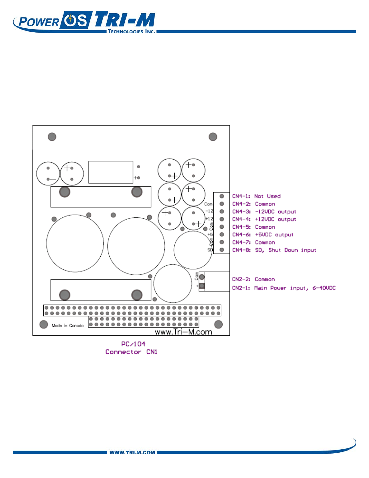
This chapter describes the configuration and installation of the HE104-75W power supply. In
addition, section 2.2 provides a formula to calculate the available +5VDC. Figure 2-1 shows the
HE104-75W connectors .
Page 8
9.0
)4
.2*]12[4.2*]12[(
155
II
AV o u tp
U sable
+−
−=+
2.2 Power Considerations.
The +5V switching regulator is rated at 15A maximum output, however the +5V output supplies power
to the +12, and -12VDC regulators. To obtain the usable range of +5V output, “derate” according to
the use of +12, -5, and -12VDC. Use the following formulae to calculate the maximum usable output.
Where: I[-12] = -12VDC current load
I[12] = 12VDC current load
Assuming 90 percent converter efficiency (actual efficiency may vary).
2.3 Main (CN2) Input Power Connector
Input power is connected to the HE104-75W by removable connector blocks CN2. The power supply
accepts DC input voltages in the range of 6VDC to 40VDC.
Unregulated vehicle power is connected as follows:
- Terminal 1:“hot” polarity (6-40VDC)
- Terminal 2: Common (0VDC)
2.4 Output (CN4) Power Connector
Output power is available for use via connector block CN4 and is applied directly to the power and
ground connections on the PC/104 bus (refer to 2.2.3 for a listing of power and ground connections
on the PC/104 bus).
Note: SD is an opto-coupled input signal used to turn on/off the outputs. To enable the HE104-75W
outputs, a 6 to 40V signal must be connected to the SD input. If remote control is not required, the
SD input can be connected to the main power input. The common for the remote 6 to 40V signal
must be connected to the HE104-75W common. If the SD input is connected directly to the main
input power connector, the common for the SD input is already done.
CN4 Connections
- CN4-1: Not populated
- CN4-2: Common
- CN4-3: -12VDC output
- CN4-4: +12VDC output
- CN4-5: Common
- CN4-6: +5VDC output
- CN4-7: Common
- CN4-8: SD (i.e. maintained contact closure)
[email protected] Toll-free (Canada & USA) 1-800-665-5600
2013-03-14 8 Direct: +1-604-945-9565
Page 9
Pin #
Signal
Pin #
Signal
Pin #
Signal
Pin #
Signal
A1
Not Used
B1
GND
C0
GND
D0
GND
A2
Not Used
B2
Not Used
C1
Not Used
D1
Not Used
A3
Not Used
B3
+5V
C2
Not Used
D2
Not Used
A4
Not Used
B4
Not Used
C3
Not Used
D3
Not Used
A5
Not Used
B5
Not Used
C4
Not Used
D4
Not Used
A6
Not Used
B6
Not Used
C5
Not Used
D5
Not Used
A7
Not Used
B7
-12V
C6
Not Used
D6
Not Used
A8
Not Used
B8
Not Used
C7
Not Used
D7
Not Used
A9
Not Used
B9
+12V
C8
Not Used
D8
Not Used
A10
Not Used
B10
Not Used
C9
Not Used
D9
Not Used
A11
Not Used
B11
Not Used
C10
Not Used
D10
Not Used
A12
Not Used
B12
Not Used
C11
Not Used
D11
Not Used
A13
Not Used
B13
Not Used
C12
Not Used
D12
Not Used
A14
Not Used
B14
Not Used
C13
Not Used
D13
Not Used
A15
Not Used
B15
Not Used
C14
Not Used
D14
Not Used
A16
Not Used
B16
Not Used
C15
Not Used
D15
Not Used
A17
Not Used
B17
Not Used
C16
Not Used
D16
+5V
A18
Not Used
B18
Not Used
C17
Not Used
D17
Not Used
A19
Not Used
B19
Not Used
C18
Not Used
D18
GND
A20
Not Used
B20
Not Used
C19
Not Used
D19
GND
A21
Not Used
B21
Not Used
A22
Not Used
B22
Not Used
A23
Not Used
B23
Not Used
A24
Not Used
B24
Not Used
A25
Not Used
B25
Not Used
A26
Not Used
B26
Not Used
A27
Not Used
B27
Not Used
A28
Not Used
B28
Not Used
A29
Not Used
B29
+5V A30
Not Used
B30
Not Used
A31
Not Used
B31
GND
A32
GND
B32
GND
Description
Part Number
Manufacturer
Part Location
2Pos Plug, MOLEX 0.156"
09-50-8021-P
MOLEX
Plug for CN2
CRIMP TERMINAL, 24-18AWG .156"
08-50-0106
MOLEX
Crimps for CN2
2.5 PC/104 Bus Connector
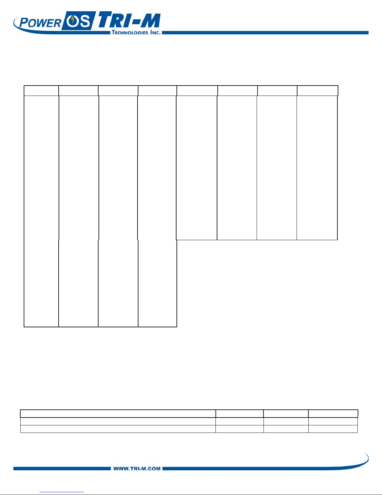
The table below lists the pins used by the HE104-75W for power and ground on the PC/104 bus.
2.6 LED Enable/Disable
There are no jumpers on the HE104-75W to disable the LED. If the LEDs must be disabled then the
current limiting resistor can be easily removed. The HE104-75W can be factory ordered in this
configuration for OEM quantities. Please contact Tri-M sales for det ai ls .
2.7 Connector Part Numbers
 Loading...