

Trim Servo 104626-007, 104626-010, 104626-011, 104626-012, 104627-007 Installation Guide
...Page 1
Trim Servo – Installation Guide
104679-000, Rev A
Copyright © 2023 by Corgi Aviation – Corgi Aviation grants third parties' permission to print this document.
Page | 1
Thank you for purchasing a Corgi Aviation Trim Servo. Corgi Aviation's trim servos are designed
to control trim surfaces and other systems in homebuilt and other light aircraft applications. They
are commonly installed alongside modern autopilot systems to provide auto-trim functionality,
which reduces the need for pilots to trim the aircraft manually when under autopilot control.
This Installation Guide provides an overview of what is included with your servo and what is
needed for installation. The information herein applies to the following Corgi Aviation Trim Servo
models:
PART #
NAME / DESCRIPTION
104626-007
CA-07C Trim Servo, 0.7IN, Clevis End
104626-010
CA-10C Trim Servo, 1.0IN, Clevis End
104626-011
CA-11C Trim Servo, 1.1IN, Clevis End
104626-012
CA-12C Trim Servo, 1.2IN, Clevis End
104627-007
CA-07T Trim Servo, 0.7IN, Threaded End
104627-011
CA-11T Trim Servo, 1.1IN, Threaded End
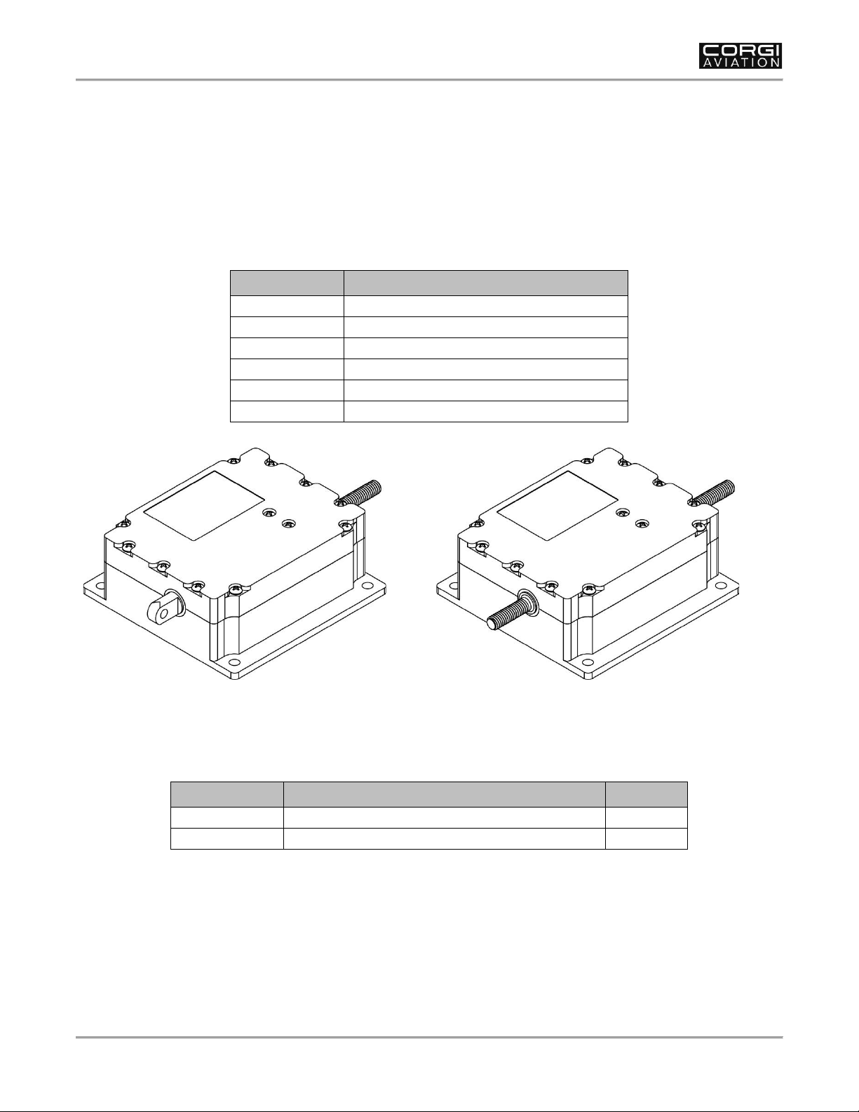
Figure 1: Corgi Aviation Trim Servo (Clevis and Threaded Shaft Models)
Included Items
The following items are also included with your purchase:
PART #
NAME / DESCRIPTION
AMOUNT
100196-003
5-PIN MOLEX MICROFIT CONNECTOR (MALE)
1
100202-000
MICROFIT PIN CRIMP (FEMALE)
5
Page 2
Trim Servo – Installation Guide
Page | 2
104679-000, Rev A
Copyright © 2023 by Corgi Aviation – Corgi Aviation grants third parties' permission to print this document.
Unit Installation
Mounting locations for trim servos vary by aircraft type and the control surface receiving the trim
servo. Installers will need to determine the best mounting location for their application. Trim
servo shaft travel needs to be considered when making this determination.
The following is a list of guidelines for mounting a trim servo:
• If replacing a trim servo, mount the unit in same location as existing trim servo.
• If installing a new trim servo, mount the unit near the trim tab control, ensuring the area
is not prone to extreme water exposure.
• Avoid riveting the unit directly to airplane structure, as this will hinder future servicing or
removal/replacement.
Mounting hardware is not included with the trim servo. Use aviation standard
screws and locknuts or nutplates to mount the unit to the aircraft's structure.
To mount the Trim Servo:
1. Determine best mounting location (see guidelines above).
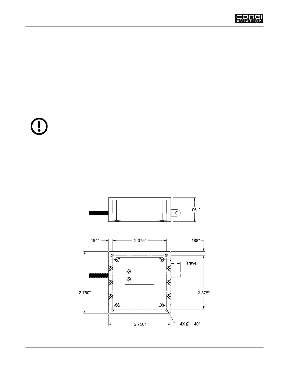
2. Use mounting holes on unit (see Figure 2) as template to mark hole locations on aircraft
structure.
3. Drill up to #32 holes, and then deburr as needed.
4. Secure unit to aircraft structure with #6 aviation-standard hardware.
Figure 2: Trim Servo Mounting Dimensions (All Models)
Page 3
Trim Servo – Installation Guide
104679-000, Rev A
Copyright © 2023 by Corgi Aviation – Corgi Aviation grants third parties' permission to print this document.
Page | 3
Electrical Connection
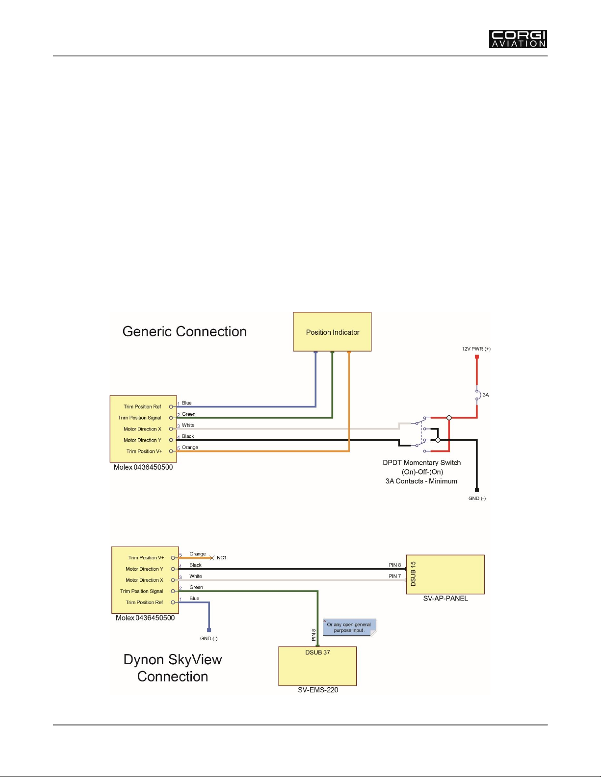
Installers will need to fabricate a 5-pin wire harness using at least 24 AWG wire (not included)
and the included Molex connector and pin crimps. Pins must be crimped using Molex 638190000
or equivalent. See Figure 3 for pin/wire allocation, depending upon your installation.
To electrically connect the Trim Servo:
1. Make sure aircraft power is disconnected.
2. If connecting to a manual trim switch, make sure circuit is protected by a 3A circuit
breaker/fuse (see aircraft manufacturer's documentation for guidance).
3. Wire and terminate servo trim harness according to the appropriate diagram in Figure 3.
4. Support and secure servo trim harness while routing through the airframe to avoid high
heat, sharp edges, and moving components.
5. Connect servo trim harness to trim servo.
6. Reconnect aircraft power.
Figure 3: Electrical Connections Diagram
Page 4
Trim Servo – Installation Guide
Page | 4
104679-000, Rev A
Copyright © 2023 by Corgi Aviation – Corgi Aviation grants third parties' permission to print this document.
Control Connection
As trim tab control components vary between aircraft types, installers will need to source
necessary aviation-standard hardware to connect the trim servo shaft to the trim tab control. The
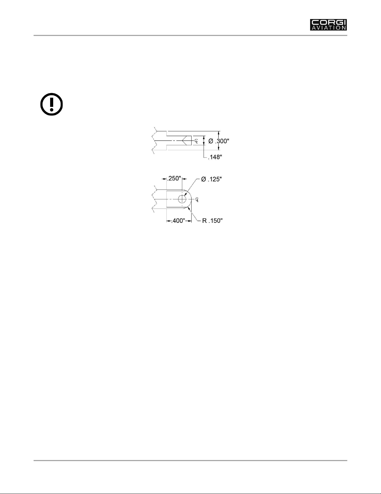
shaft on models CA-07C, -10C, -11C, -12C has a clevis end (see Figure for specifications); the
shaft on models CA-07T and -11T has #10-32 threads for connection.
DO NOT alter clevis end! Doing so will weaken the connection and may result
in trim control failure.
Figure 4 Clevis End Specifications (Models CA-07C, -10C, -11C, -12C)
To connect the Trim Servo to trim tab control:
1. Secure trim tab in neutral position.
2. Position trim servo shaft at half extension.
3. Measure distance between trim servo shaft end and trim tab control.
4. Size connecting rod as needed.
5. Attach trim servo shaft to trim tab control rod with aviation-standard hardware.
Page 5
Trim Servo – Installation Guide
104679-000, Rev A
Copyright © 2023 by Corgi Aviation – Corgi Aviation grants third parties' permission to print this document.
Page | 5
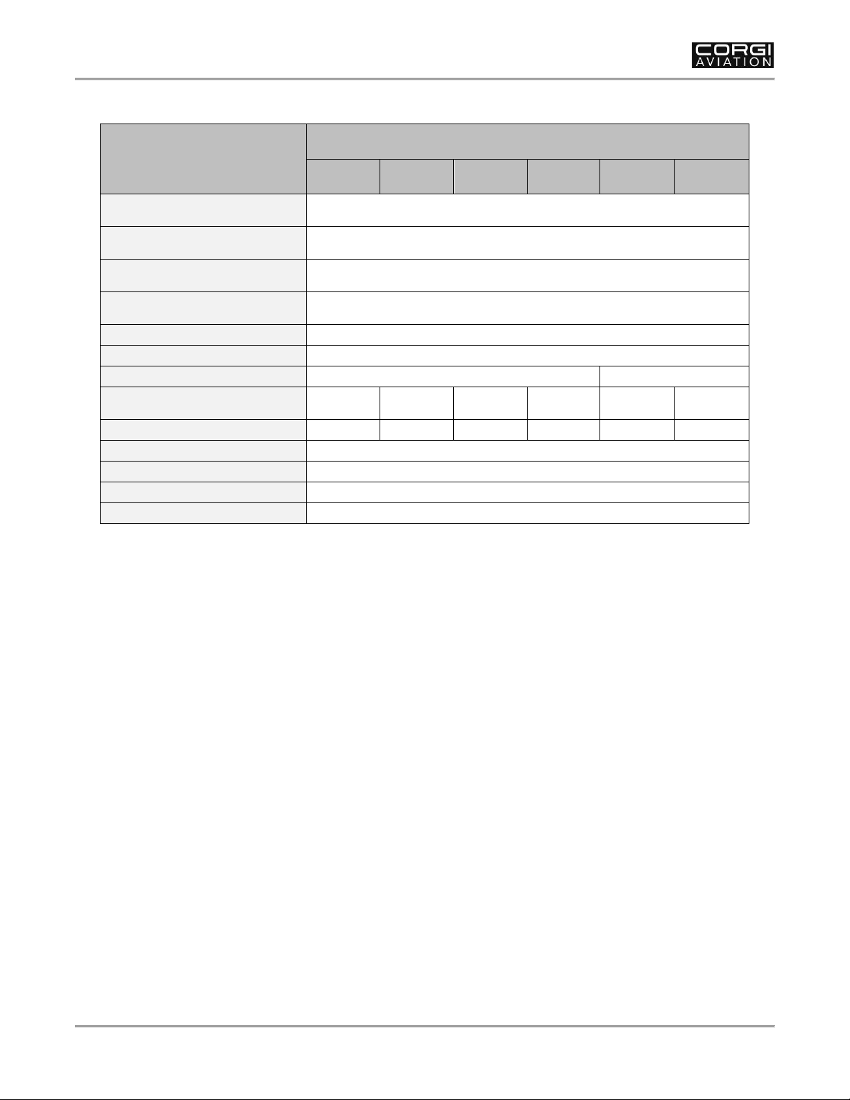
Specifications
SPECIFICATION
MODEL NUMBER
CA-07C
CA-10C
CA-11C
CA-12C
CA-07T
CA-11T
Dimensions (L x W x H)
2.750in. x 2.750in. x 1.061in.
(69.9mm x 69.9mm x 27.0mm)
Weight
4.8oz.
(.17kg)
Operating Temperature
-22F to 140F
(-30C to 60C)
Storage Temperature
-40F to 158F
(-40C to 70C)
Operating Voltage
6-15V DC
Housing Material
Glass-filled Nylon
Shaft End Type
Clevis
Threaded #10-32
Shaft Travel
0.7in.
(17.8mm)
1.0in.
(25.4mm)
1.1in.
(27.9mm)
1.2in.
(30.5mm)
0.7in.
(17.8mm)
1.1in.
(27.9mm)
Travel Time (@13.5V DC)
11 Sec
14 Sec
17 Sec
18 Sec
11 Sec
17 Sec
Max Operating Thrust
50lb
Max Static Load
500lb
No Load Current (@12V DC)
95mA
Max Stall Current (@12V DC)
1.4A
 Loading...