

Page 1

USER’S MANUAL
V3 / V4
750 50 0045 03
Page 2

Page 3

Dear customer, congratulations for choosing a TRIMOS measuring instrument. For more than 40 years,
our products have built up an excellent reputation in terms of quality, accuracy and longevity. For full
satisfaction with the present product, we recommend to read this user’s manual carefully.
750 50 0045 03 Version 1.0 / 2014-09
TRIMOS ® - All modification rights reserved
TRIMOS SA
Av. de Longemalle 5
CH - 1020 Renens
T. + 41 21 633 01 01
F. + 41 21 633 01 02
www.trimos.ch
1
Page 4

User's Manual
CONTENTS
1.
Safety regulations .................................................................................................................................... 3
1.1 Important information .................................................................................................................... 3
1.2 Security symbols ........................................................................................................................... 3
1.3 General warnings .......................................................................................................................... 3
2. Instrument description ............................................................................................................................ 4
2.1 Instrument ...................................................................................................................................... 5
2.2 Interfaces/connectors ................................................................................................................... 5
2.3 Display ........................................................................................................................................... 5
2.4 Keyboard ........................................................................................................................................ 5
3. Setting up .................................................................................................................................................. 6
3.1 Packing list ..................................................................................................................................... 6
3.2 Setting-up ...................................................................................................................................... 7
4. Getting started ......................................................................................................................................... 8
4.1 Setting into operation ................................................................................................................... 8
5. Main functions ........................................................................................................................................ 10
5.1 Selection of height and diameter / centerline measurements ................................................... 10
5.2 Height measurements ................................................................................................................. 10
5.3 Diameter and centerline measurements ..................................................................................... 11
5.4 References ................................................................................................................................... 13
5.5 Selection of the resolution .......................................................................................................... 13
5.6 Setting / memorizing of the probe constant .............................................................................. 13
5.7 Selection of the measuring unit .................................................................................................. 14
5.8 Measuring in Min / Max / Delta mode ....................................................................................... 14
5.9 Average between 2 last measurements ..................................................................................... 16
5.10 Difference between 2 last measurements .................................................................................. 17
5.11 Zero setting of the display .......................................................................................................... 17
6. Secondary functions .............................................................................................................................. 18
6.1 Inversion of the measuring direction .......................................................................................... 18
6.2 Probe Holder Change ................................................................................................................. 19
6.3 Shrinking factor ........................................................................................................................... 19
6.4 Display modes ............................................................................................................................. 20
6.5 Manual recording of the probe constant ................................................................................... 20
7. Data transfer and print-out ................................................................................................................... 21
7.1 USB Connection .......................................................................................................................... 21
7.2 RS232 Connection ...................................................................................................................... 22
8. Configuration .......................................................................................................................................... 23
9. Application and adjustments ............................................................................................................... 26
9.1 Probing ......................................................................................................................................... 26
9.2 Air Cushion (V4) .......................................................................................................................... 26
9.3 Adjustment of floating probe suspension balancing ................................................................. 27
9.4 Replacement of battery block ..................................................................................................... 27
9.5 Recycling of electronic components .......................................................................................... 27
9.6 Resetting of the instrument ......................................................................................................... 28
9.7 Cleaning ....................................................................................................................................... 28
10. After sales service ................................................................................................................................. 28
10.1 Complaints / repairs .................................................................................................................... 28
10.2 Agents .......................................................................................................................................... 28
11. Technical specifications ....................................................................................................................... 29
12. Dimensions ............................................................................................................................................. 30
750 50 0045 03 2
Page 5
V3 / V4
1. SAFETY REGULATIONS
1.1 Important information
In order to prevent any damages due to wrong manipulation, please carefully read the following
instructions. TRIMOS will not accept any responsibility in case of damages caused by inadequate use not
in line with the present manual.
1.2 Security symbols
The following security symbols are used in this manual:
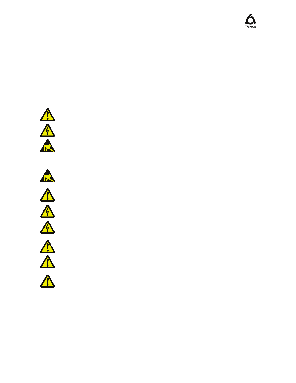
General warning, utilisation advice
Risk of electric shock
Electrostatic protection
1.3 General warnings
Protection against electrostatic interferences:
Static electricity can damage the electronic components of the instrument. In order to prevent
this type of damages, avoid any contact with the connector pins.
In order to prevent any changes of the instrument performance or any accident, the instrument
should never be dismantled.
If, for any reason, the electronic unit has to be opened, only authorized personnel are allowed
to do so.
Do not expose the instrument, its components and accessories to rain or any projection of
fluids. Avoid penetration of foreign substances into the connectors and the instrument
openings.
Do not cover or wrap the display unit during use. The unit must be kept well ventilated to avoid
any overheating.
In case of problems with the instrument or any of its parts (no display, overheating, abnormal
smell...), immediately switch off the instrument and disconnect the power supply. Please
contact your local TRIMOS agent.
This is a high accuracy instrument. Particular care should be taken during its entire operational
lifetime. Pay special attention to the following specific points :
- Use the instrument on a stable, smooth and clean surface plate.
- Avoid any shock to prevent the instrument from losing some or all of its performing
characteristics.
- Use the instrument in a vibration free area.
- Avoid exposure to direct sunlight and excessive humidity.
- Avoid proximity of heating or air conditioning systems.
- Respect the advised environmental conditions.
750 50 0045 03 3
Page 6
User's Manual
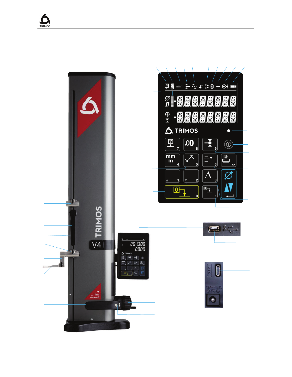
2. INSTRUMENT DESCRIPTION
2.4
8 9 7
5 4 3
2 1 6
2.1
2.3
21
22
23
24
25
26
27
28
29
30
31
32
33
34
35
36
40
41
42
43
44
45
37
38
39
47
48
49
50
51
52
46
53
2.2
10
11
12
13
14
750 50 0045 03 4
Page 7

V3 / V4
2.1 Instrument
1. Upper probe holder (V4)
2. Screw for the adjustment of the floating probe suspension
3. Handle for carriage displacement
4. Transport safety screw for locking of probe suspension (chromium plated)
5. Lower probe holder
6. Insert holder
7. Measuring insert
8. Operating handle for the displacement of the instrument
9. Base with air cushion system for instrument displacement (V4)
10. Button for activation of air cushion and programmable functions keys (V4)
11. Handwheel for measuring carriage displacement and probing movement
2.2 Interfaces/connectors
12. Mini USB connector (on top of display unit)
13. Connector for RS232 communication (on lower right side of height gauge)
14. AC adaptor connection (on lower right side of height gauge)
2.3 Display
21. Number of current reference
22. Function indicator
23. Active measuring unit
24. Probe constant indicator
25. Min / Max / Delta mode indicator
26. Inversion of measuring direction indicator
27. Probe holder change indicator
28. Shrinking factor ≠ 1 indicator
29. Direct display mode indicator
30. Motorisation indicator
31. Battery charge level indicator
32. Probing indicator
33. "Diameter/centreline" mode – Value of diameter indicator
34. Height measurement and probing direction indicator
35. "Diameter/centreline" mode – Value of centreline indicator
36. Tolerance limit/difference mode indicator
37. Upper display line
38. Lower display line
39. Visual signal of function activation
2.4 Keyboard
40. Selection of references / numeric function 7
41. Selection of resolution / numeric function 8
42. Selection of measuring unit (mm/inch) / numeric function 4
43. Min, max or delta mode/ numeric function 5
44. Up arrow / numeric function 1
45. Down arrow / numeric function 2
46. Zero setting of the display / numeric function 0
47. On/Off key (power ON / OFF)
48. Storage of probe constant / numeric function 9
49. Print-out of data / Function "+/-"
50. Average of last 2 measurements / numeric function 6
51. Function key: Selection of height and diameter - centerline measurements / Validation key
52. Difference between last 2 measurements / numeric function 3
53. Sets the display to the previously input preset value of the current reference / Function ".".
750 50 0045 03 5
Page 8
User's Manual
3. SETTING UP
3.1 Packing list
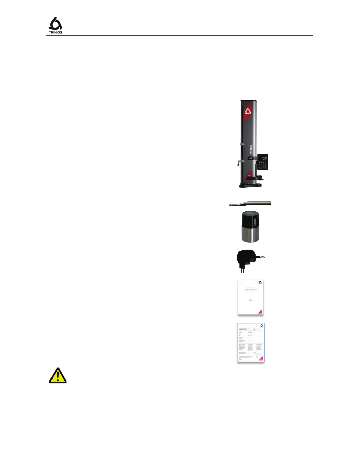
The standard packing of the instrument includes the following elements:
1. Instrument with display unit and measuring
insert holder
2. Measuring insert
3. Setting gauge
4. Charging unit
5. User’s manual
6. Calibration certificate
While unpacking, carry the instrument by lifting if by its displacement handle (8) and body. In
NO case should the instrument be carried by the handle for carriage displacement (3).
Keep the original packaging for future transportation.
If the instrument has been stored at a temperature below 5°C, wait a few hours before
unpacking to prevent the instrument parts from condensation. Condensation can affect
sensitive parts of the instrument.
750 50 0045 03 6
Page 9
V3 / V4
3.2 Setting-up
After unpacking, prepare the instrument as follows:
1. Clean the pads positioned underneath the base using a
clean cloth, slightly dampened with alcohol.
2. Position the instrument with care on a clean measuring
plate.
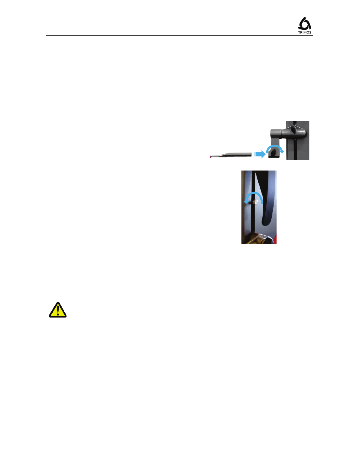
3. Slide the measuring insert into the holder and lock it,
using the knob. Take care to position the eccentric
probes correctly.
4. Release the transport safety screw (chromium-plated).
Note:
Do not try to remove the screw (screw stop)!
5. If the instrument does not switch on or in case of low
battery level, proceed to a full loading of the batteries
(plug in the charging unit to the instrument). Empty
batteries are fully loaded in about 3 hours.
Only use the charging unit supplied with the instrument to load the batteries.
It is not necessary to wait until the battery pack is fully charged. The instrument becomes
operational immediately after having connected the charging unit.
It is not dangerous to leave the charging unit connected. Permanently plugged-in instruments
automatically switch to trickle charge mode.
The batteries are of Lithium-ion type. An excessive room temperature can affect the battery
capacity and therefore the instrument autonomy. It is not recommended to load the battery
in case of room temperature superior to 40C°.
Incorrect loading of the battery can result in a decrease of capacity, overheating, or even an
explosion and cause important damages.
The charging units can be loaded and unloaded 300 times before a significant reduction of
their capacity. The number of loading cycles and the autonomy can vary according to use
and operating conditions.
750 50 0045 03 7
Page 10
User's Manual
4. GETTING STARTED
4.1 Setting into operation
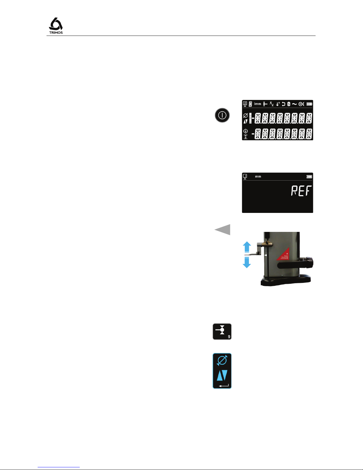
1. Switch on the instrument by pressing button On/Off
during 2 seconds. All segments of the display will light
up.
Switch off the instrument by pressing the same button
until the instrument turns off.
> 2 s
2. The display will ask for the reference position. Move the
measuring carriage slowly across the mark indicating
the reference position with the help of the handle for
carriage displacement (the acquisition of reference is
carried out by displacing the carriage upwards). An
acoustic signal will confirm that the reference has been
detected and the display starts counting. If the display
does not start counting, repeat the sequence.
Note :
V5/V6: This procedure is carried out automatically in
motorized mode.
3. The instrument is now asking for the probe constant.
This function compensates the dimension and the
deflexion of the measuring insert when probing
downwards and upwards (reversed surfaces,
diameters). The last stored probe constant value will be
displayed.
Note 1 :
This procedure may be interrupted by pressing on the
probe constant key or on the
Validation key
. The latest
probe constant value measured is then recorded.
Note 2 :
The start mode can differ, according to the instrument
configuration (§
8).
.
ou
750 50 0045 03 8
Page 11
V3 / V4
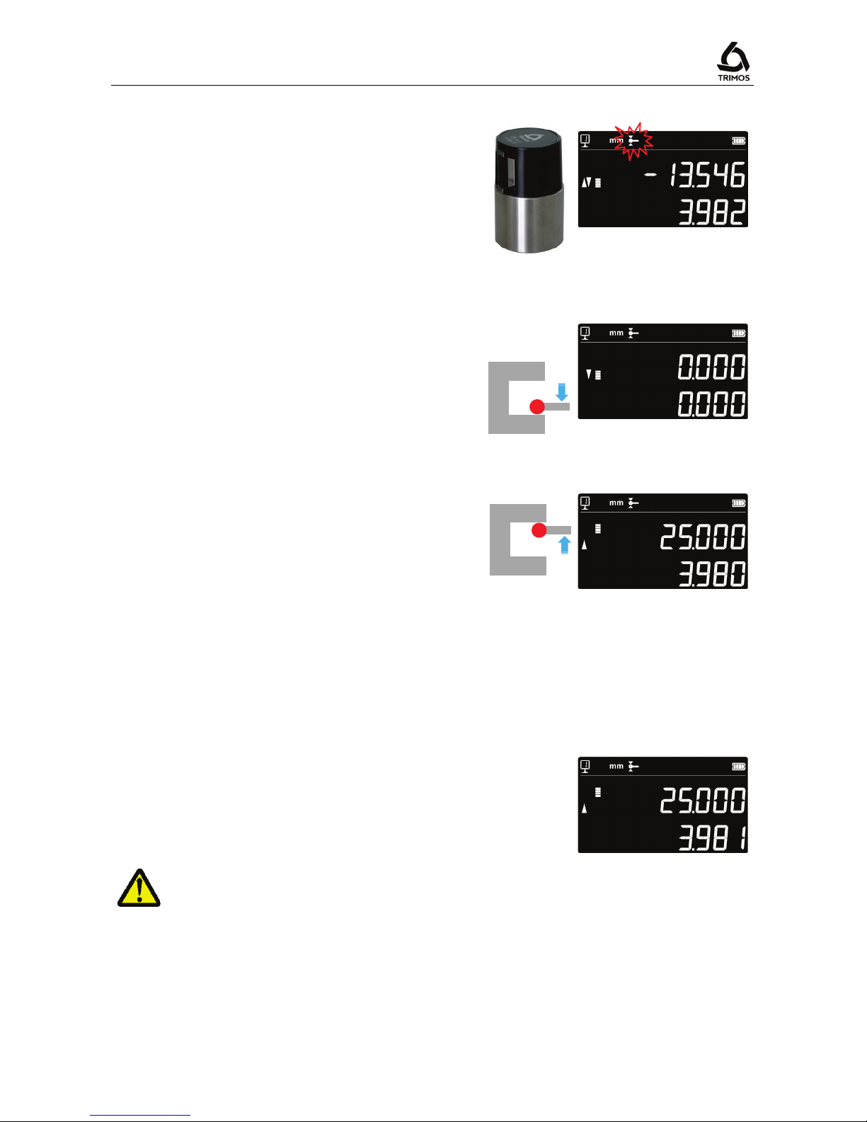
4. Use the setting gauge supplied with the instrument to
carry out this operation.
Note:
A different setting gauge may be used. In this case, its
dimension must be configured in the set-up menu (§ 8).
5. Move the measuring insert downwards (use the
handwheel for the displacement of the measuring
carriage) until it touches the surface and an acoustic
signal confirms the measurement (=probing).
6. Without moving any part (instrument and gauge), move
the measuring insert towards the top and perform the
same sequence on the upper surface of the setting
gauge.
7. Repeat the sequences 5 and 6 one more time. This
allows establishing the probe constant more precisely.
2x
8. The screen will display the setting gauge value during
the latest probing, as well as that of the new probe
constant. The instrument is then ready to be used.
The probe constant needs to be checked and stored again after each measuring insert
change, after change of its position in the holder, after each adjustment of the measuring
force or adjustment of the floating probe suspension.
750 50 0045 03 9
Page 12
User's Manual
5. MAIN FUNCTIONS
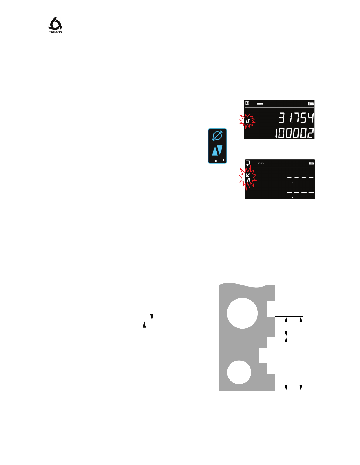
5.1 Selection of height and diameter / centerline measurements
To select the functions of height measurements or
diameter/centreline distances, press the
Function key
.
The corresponding symbol will be displayed.
Height
diameter / centerline
5.2 Height measurements
H1 = Height measurement downwards ( )
H2 = Height measurement upwards ( )
H12 = Chain dimensions
H1
H2
H12
750 50 0045 03 10
Page 13
V3 / V4
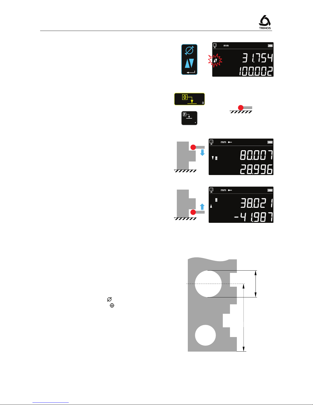
1. Select height measurement mode.
2. Set the display at zero or at a preset value with the
measuring insert probing a reference surface (see §
5.11 and § 5.4.2).
ou
3. Probe the surface to be measured downwards or
upwards. The probing indicator will display the
progression of the measuring force application.
When the right force is reached, an acoustic signal
will confirm the measurement.
Note:
The first line of the display indicates the height
measured.
The second line indicates the distance from the
former height measurement (chain of dimensions).
This display mode can be configured (§ 6.4).
5.3 Diameter and centerline measurements
D = Diameter measurement ( )
C = Centreline measurement ( )
D
C
750 50 0045 03 11
Page 14
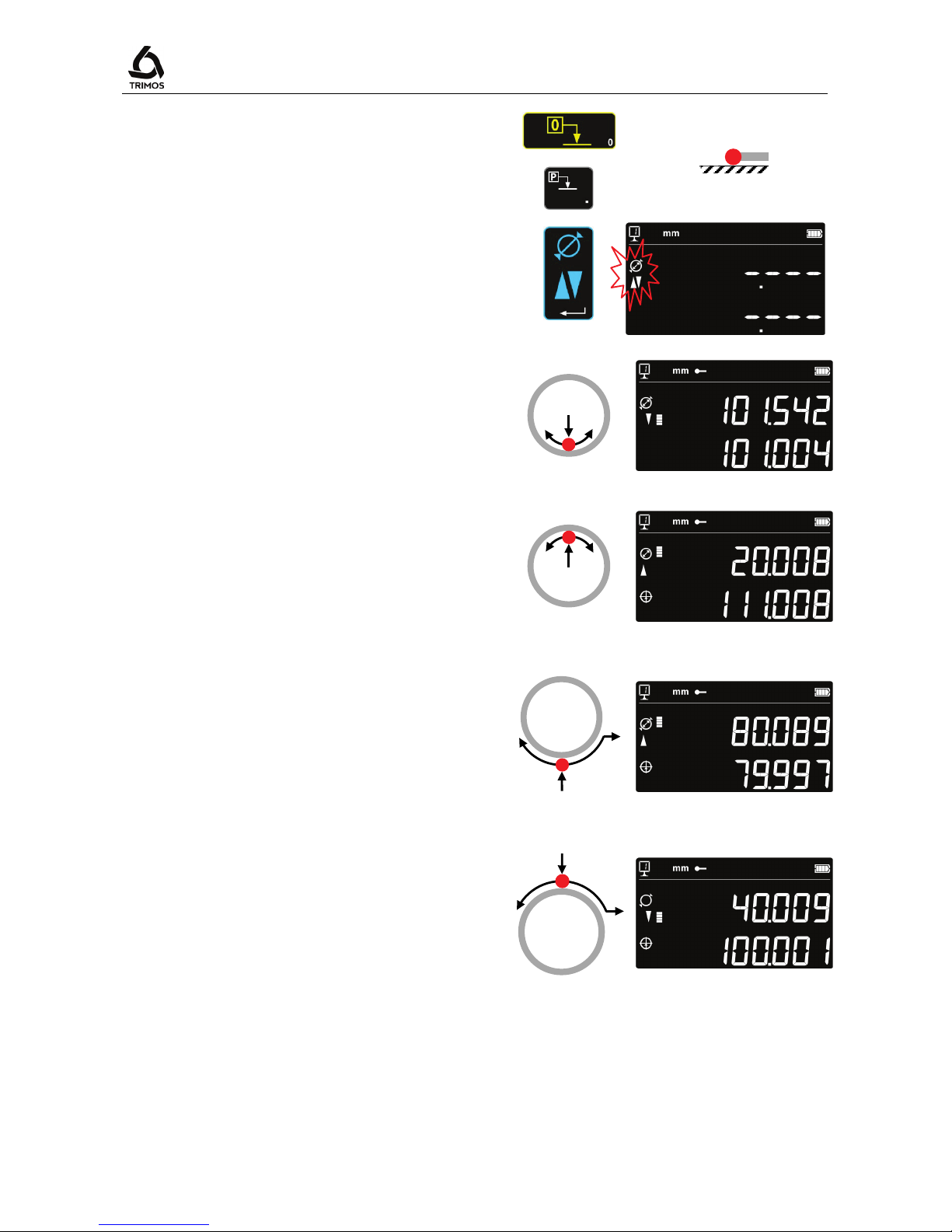
User's Manual
1. Set the display at zero or at a preset value on a
reference surface (see § 5.11 and § 5.4.2).
ou
2. Select the diameter / centerline mode by pressing
the
Function key
.
3a. Internal diameter :
Position the measuring insert into the bore and set
it on the lower profile as near as possible to the
reversal point (1). Engage the measuring force until
the acoustic signal. Move the instrument (or the
part) laterally to determine the reversal point (2).
The reversal point is stored automatically.
4a. Move the measuring insert straight up and set it on
the upper profile as near as possible to the reversal
point (3). Engage the measuring force until the
acoustic signal. Move the instrument (or the part)
laterally to determine the reversal point (4).
Diameter and centreline values are displayed on
the 1
st
and 2nd lines of the display respectively.
3b. External diameter
Set the measuring insert off center on the lower
shaft profile as near as possible to the reversal
point (1). Engage the measuring force until the
acoustic signal. Move the instrument (or the part)
laterally to determine the reversal point (2). It is
automatically stored. Remove the measuring insert
slowly to the side, off center (3).
4b. Set the measuring insert on the upper shaft profile
as near as possible to the reversal point (4).
Engage the measuring force until acoustic signal.
Move the instrument (or the part) laterally to
determine the reversal point (5). Remove the
measuring insert slowly to the side, off center (6).
Diameter and centreline values are displayed on
the 1
st
and 2nd lines of the display respectively.
5. When the measuring insert is removed, the display
remains frozen on the diameter and centerline
values.
Restart with point 3a or 3b for a new measurement.
1
2
3
4
3
1 2
6
4
5
750 50 0045 03 12
Page 15
V3 / V4
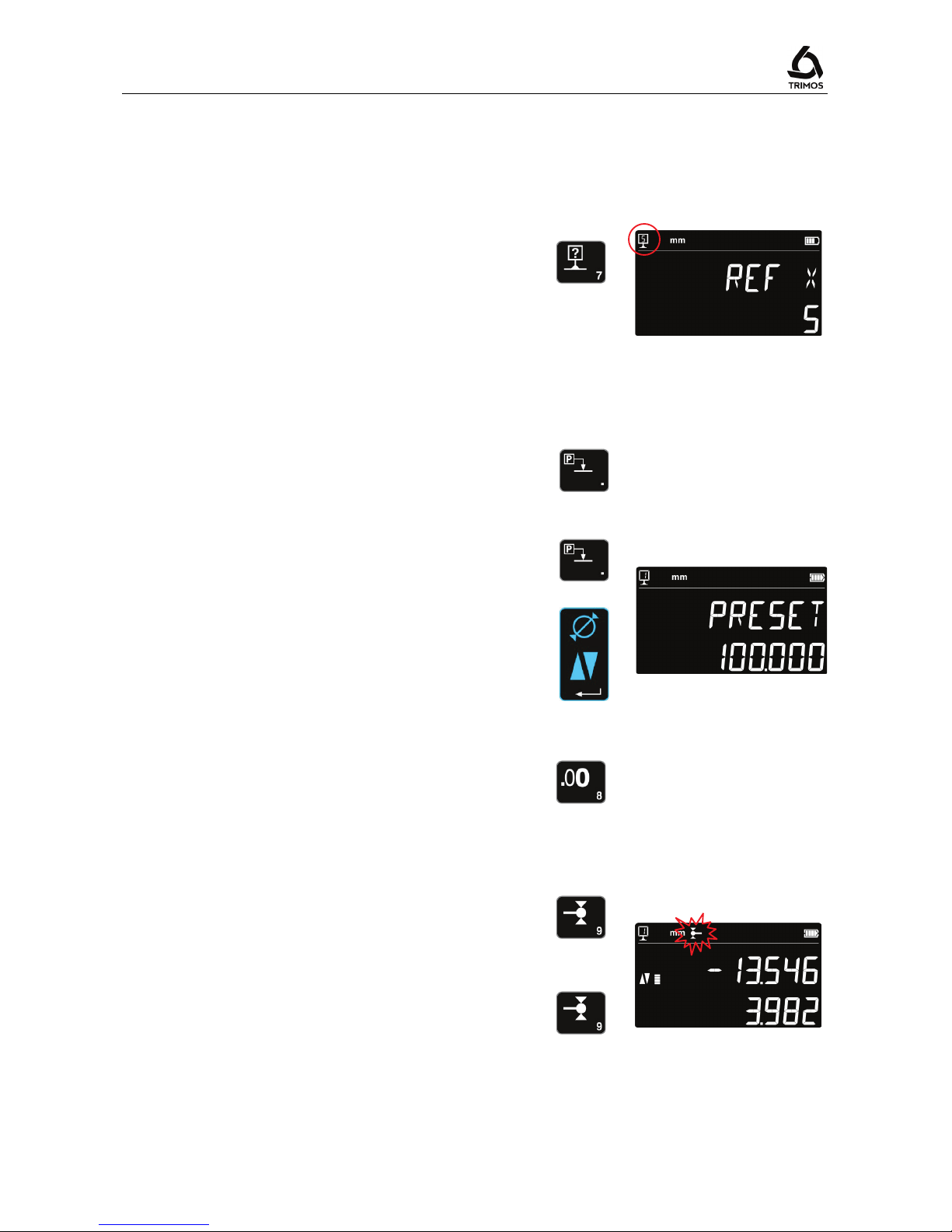
5.4 References
5.4.1 Selection of references
The use of references allows a parallel measurement starting
from different points of origin (=references).
The current reference is mentioned at the top left hand side
of the display. For reference change, press reference key
and enter the reference number.
Note :
It is possible to choose the number of references (from 1 to
9). To configure the number of references, see § 8.
5.4.2 Assignment of a preset value to a reference
By pressing the Preset key, the previously entered preset
value for each selected reference will be taken into
consideration for height measurements, centerline distances
or Min / Max values.
In direct mode (see § 6.4
), the preset is executed at the
current position of the probe.
A preset value can be assigned to each reference.
Select the required reference and press the
Preset
key
longer than 2 seconds. Enter the value and confirm by
pressing the
Validation key
key.
>2 s
5.5 Selection of the resolution
To modify the display resolution, press key opposite
5.6 Setting / memorizing of the probe constant
To check and memorize the probe constant, press the
following key and follow the same sequence as for "Setting
into operation" (§ 4.1, points 4 to 8).
Note 1:
The current constant value is shown on the second line of
the display by pressing this key once. A second pressure
interrupts the acquisition of constant and brings the
instrument back into height measuring mode.
The constant value of the probe can also be manually (§
6.5).
or
>2 s
750 50 0045 03 13
Page 16
User's Manual
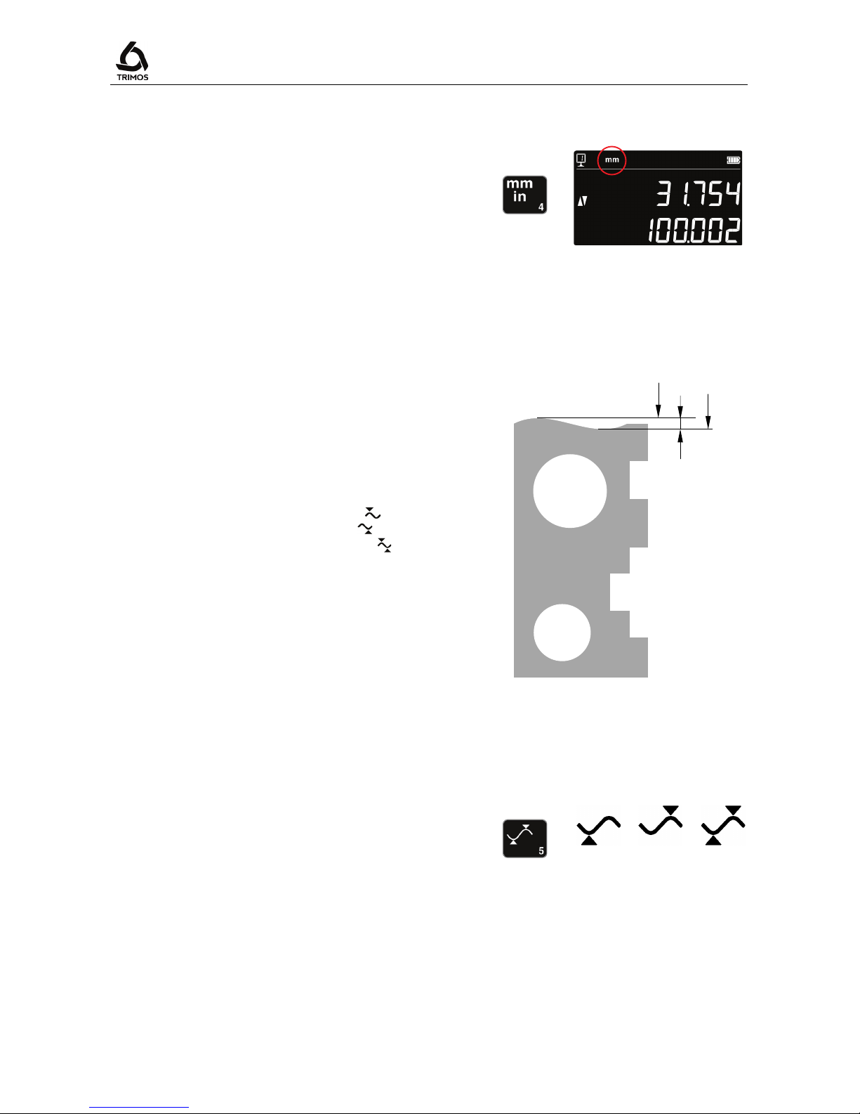
5.7 Selection of the measuring unit
Measurements can be performed either in mm or in inch. To
change the unit, press the
mm/in
key. The active unit is
displayed below the probing indicator.
Note:
It is possible to lock in the required measuring unit (§ 8).
5.8 Measuring in Min / Max / Delta mode
Max = Measurement of maximum value ( )
Min = Measurement of minimum value ( )
Delta = Difference between Max and Min ( )
The measurements in mode Min, Max Delta have always to
be done with the probe being in contact with the surface.
It allows to determine the following values :
Min
: Minimum value of the measured surface
Max
: Maximum value of the measured surface
Delta
: Difference between the maximum and minimum
value
To select the Min, Max or Delta mode, press the key on the
keyboard. By pressing the same key several times, the
required mode will be displayed. To quit this mode, press
the
Function key.
Note:
The upper line of the display shows the current position, the
lower line shows the extreme position of Min, respectively
Max or Delta reached.
Min
Max
Delta
Max
Delta
Min
750 50 0045 03 14
Page 17
V3 / V4
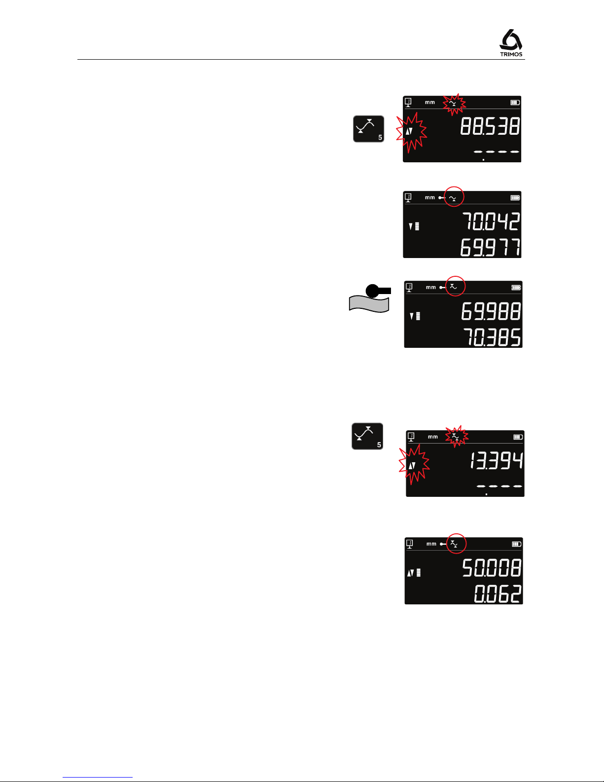
5.8.1 Measuring in Min or Max mode
1. Select Min or Max function. The corresponding
indicator shows the activated mode.
2. Probe the surface to be measured and displace the
insert or the piece along the part to be analysed. The
1st line on the display shows the instantaneous position
of the probe. The 2
nd
line indicates the minimum,
respectively maximum value reached.
Note :
A zero setting or a preset reinitialize the display on the
minimum or maximum value measured.
Min
Max
5.8.2 Measuring in Delta mode
1. Select Delta function. The corresponding indicator
shows the activated mode.
2. Probe the surface to be measured and displace the
insert or the piece along the part to be analysed. The
1st line on the display shows the instantaneous
position of the probe. The 2
nd
line indicates the
difference between the maximum and minimum
(=Delta) measured.
Note :
By pressing the
Zero
key, the Delta mode will be reset
and the display will show zero.
Delta
750 50 0045 03 15
Page 18
User's Manual
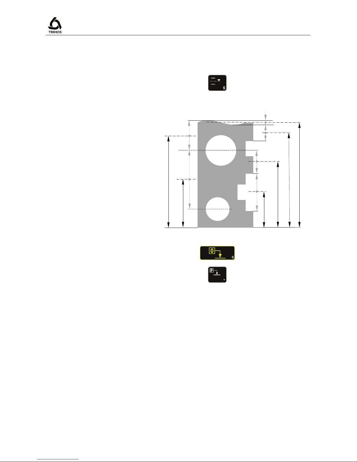
5.9 Average between 2 last measurements
By pressing this key, the average between the 2 last height
measurements, centerline, Min or Max is determined.
These various measurements can be combined with each
other.
Averages :
M1 = Between 2 centerlines
M2 = Between 2 heights
M3 = Between Min et Max
M12 = Between centreline and height
M13 = Between centreline and Min or Max
M23 = Between height and Min or Max
Note:
It is possible, after calculation of an average value, to give
the calculated position a zero value or Preset value.
ou
M1
M2
M3
M12
M23
M13
750 50 0045 03 16
Page 19
V3 / V4
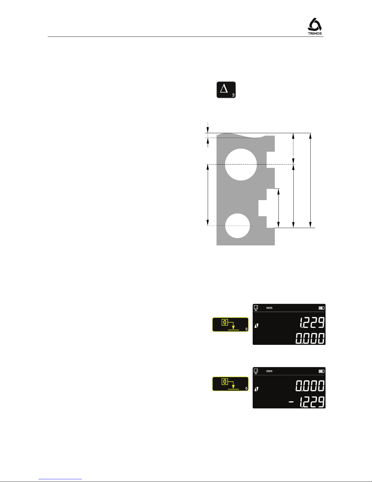
5.10 Difference between 2 last measurements
By pressing the difference key, the distance between the 2
last height measurements, centerline, Min or Max is
determined and mentioned on the 2
nd
line of the display.
These various measurements can be combined with each
other.
Distances:
D1 = Between 2 centerlines
D2 = Between 2 heights
D3 = Between 2 values Min-Min, Min-Max or MaxMax
D12 = Between centreline and height
D13 = Between centreline and Min or Max
D23 = Between height and Min or Max
5.11 Zero setting of the display
In height measuring mode a zero setting will be done on the
last surface measured by pressing the zero setting key.
In diameter / centerline mode a zero setting will be done on
the last centerline distance measured.
In Min or Max mode a zero setting will be done on the last
Min or Max value measured.
By pressing the key longer than 2 seconds, the preset value
of the current reference will be displayed, disregarding the
last probing step.
> 2 s
D1
D2
D12
D3
D23
D13
750 50 0045 03 17
Page 20
User's Manual
6. SECONDARY FUNCTIONS
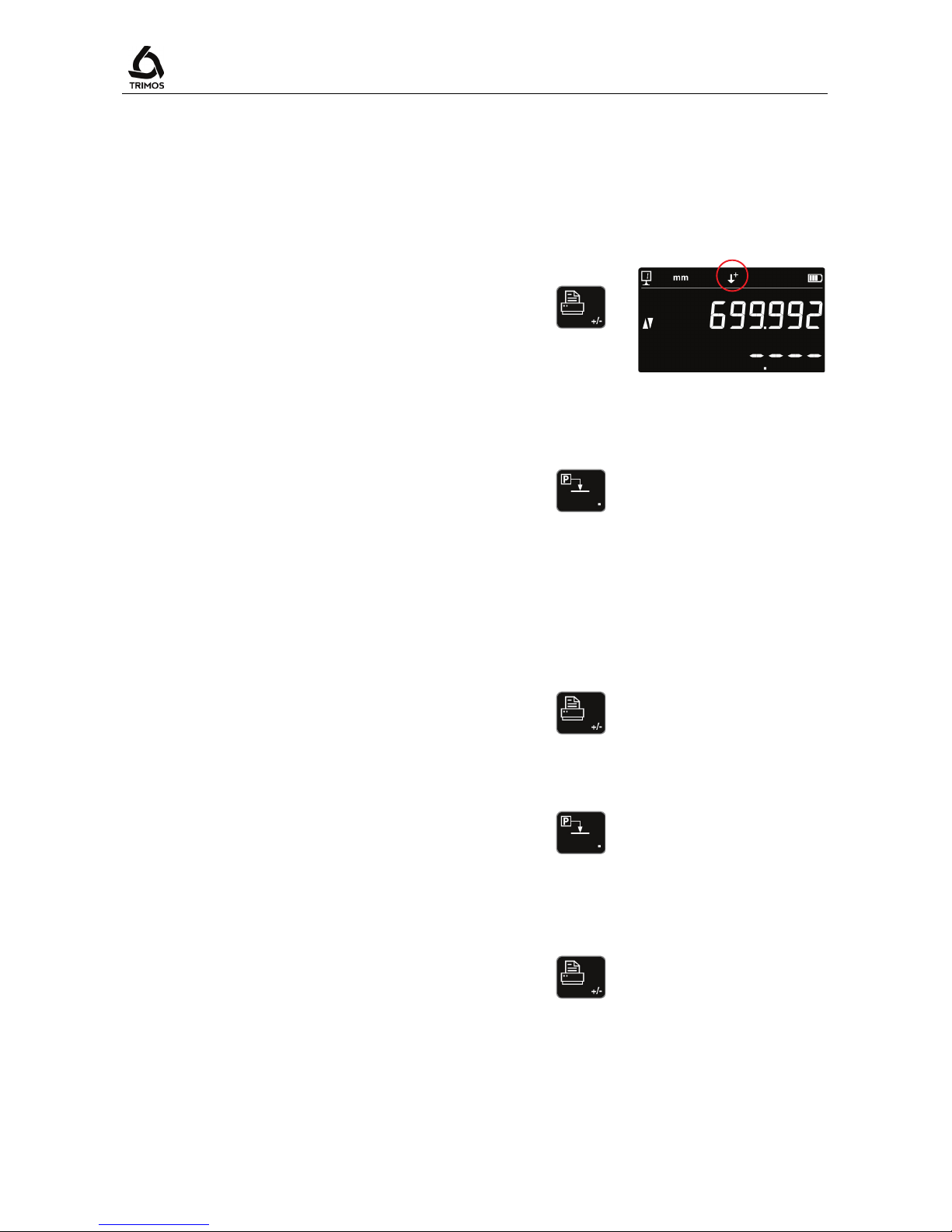
6.1 Inversion of the measuring direction
It is possible to invert the measuring direction to obtain
positive measuring values in both directions (upwards and
downwards starting at zero). This function is mainly used
when the part to be measured is higher than the measuring
range of the instrument.
Press
+/-
key during 2 seconds to revert the direction of
measurement. The inversion indicator of the measurement
direction is mentioned as long as this mode remains active.
> 2 s
Preset
Immediately after having inverted the measuring direction,
the preset value of the active reference will be replaced by
the last measured value (height or centerline) before the
inversion.
By pressing the
Preset
key, this last value will be displayed.
Afterwards, the Preset value will be the initially entered one.
Procedure:
1. Perform measurements in a normal way
2. Turn the part when having reached the limit of the
instrument range
3. Invert the measuring direction
> 2 s
4. Probe the last surface or centerline measured before
5. Press the
Preset
key (the last measured value will be
displayed)
6. Continue measuring
Quit
Quit the function of inversion of the measuring direction by
pressing once again the
+/-
key during 2 seconds
> 2 s
750 50 0045 03 18
Page 21
V3 / V4
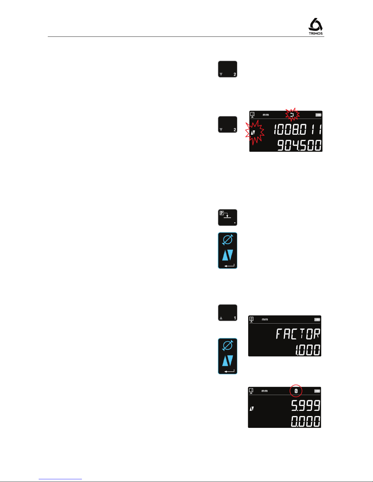
6.2 Probe Holder Change
This function allows to pass from one probe holder to
another while keeping the same origin.
Press the key opposite during 2 seconds to activate the
probe holder change function
> 2 s
Procedure to follow
1. Before taking out the insert probe a reference surface of
centerline and activate the probe holder change mode.
The function symbol is blinking..
> 2 s
2. Mount the probe on the other probe holder.
3. Probe the same surface again, or reference centreline.
4. Press
Preset
key (the display mentions the latest
measured value.
This procedure can be interrupted at any time by pressing
the
Validate
key.
6.3 Shrinking factor
A shrinking factor can be entered here, for example for
measuring injection moulds. This function allows in general
"distending" or "shrinking" the measuring system by a
defined factor.
To activate this function, press the key, shown at the right,
during 2 seconds. Enter the shrinking factor (value between
0.7 and 1.2) and confirm by pressing
Validation Key
.
> 2 s
When the shrinking factor is different from 1, the following
symbol appears at the top of the main display.
750 50 0045 03 19
Page 22
User's Manual
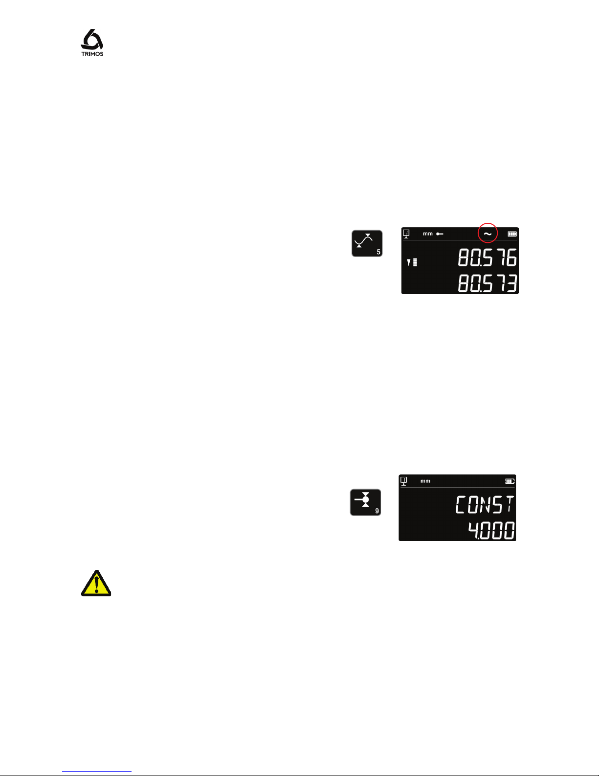
6.4 Display modes
In height measuring mode, 2 ways are possible to display
the measured value :
"Standard" display
The upper line of the display permanently indicates the
current position of the probe. It remains frozen at the
measured value during probing.
During probing the lower line indicates the distance from
the former height (Dimension in chain).
When the measuring force is released, this value is replaced
by that of the last measurement.
"Direct" display
The upper line of the display permanently indicates the
current position of the probe. It does not remain frozen
during probing.
The lower line indicates the frozen value of the last
measurement.
Activate the "direct" display mode by pressing the key
opposite during 2 seconds. Do the same to deactivate this
mode. When the "direct" display mode is activated, the
symbol opposite appears at the top of the principal display.
Note:
The "standard" and "direct" display modes only apply to
height measurements.
> 2 s
6.5 Manual recording of the probe constant
The probe constant can be introduced manually. To do so,
press the opposite function key during 2 seconds and enter
the requested value with the numeric keypad. Confirm by
pressing the
Function
key.
The registered value is taken into account during
measurements. Each new constant acquisition replaces the
old one.
> 2 s
The constant is an essential element during bidirectional measurements. Great caution
should be applied for the interpretation of the measurements results when this value is
entered manually.
750 50 0045 03 20
Page 23
V3 / V4
7. DATA TRANSFER AND PRINT-OUT
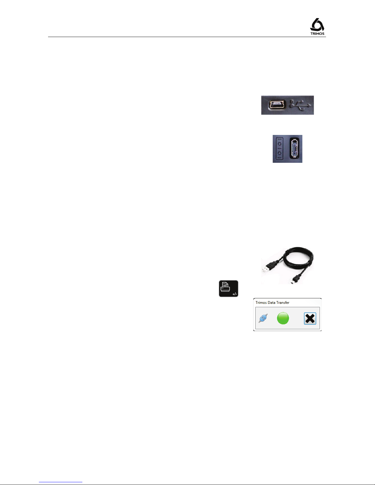
The instrument offers 2 communication ports:
Mini USB
This connector is placed at the back of the display unit. It
allows a very simple connection to a PC for the
transmission of data, upgrades, diagnosis, etc.
RS232
This connector is placed at the back of the height gauge. It
allows a classic connection with external devices equipped
with RS232 interfaces, such as printer or PC.
7.1 USB Connection
A mini-USB cable is required for the connection to a PC, as
well as the communication software TrimosDataTransfer.
Cable
Cable USB A-Mini B: TA-EL-014 (ref. 332 02 0002)
Software
The software TrimosDataTransfer is freely available on
www.trimos.ch, in the corresponding product section.
Data transfer procedure
1. Start TrimosDataTransfer
2. Connect the instrument to the PC with TA-EL-014 cable
and wait for the connection to be established
3. Click on the application to which the data has to be
transferred (i.e. Microsoft Excel)
4. Press
data transfer
key: the value is displayed at the
place having the focus.
Format
Numerical value (as on display) in ASCII characters.
750 50 0045 03 21
Page 24
User's Manual
7.2 RS232 Connection
Data transmission
- Speed : 4800 baud
- ASCII Code : 7 bits
- Parity : even
- Stop bits : 2
- Handshake : without
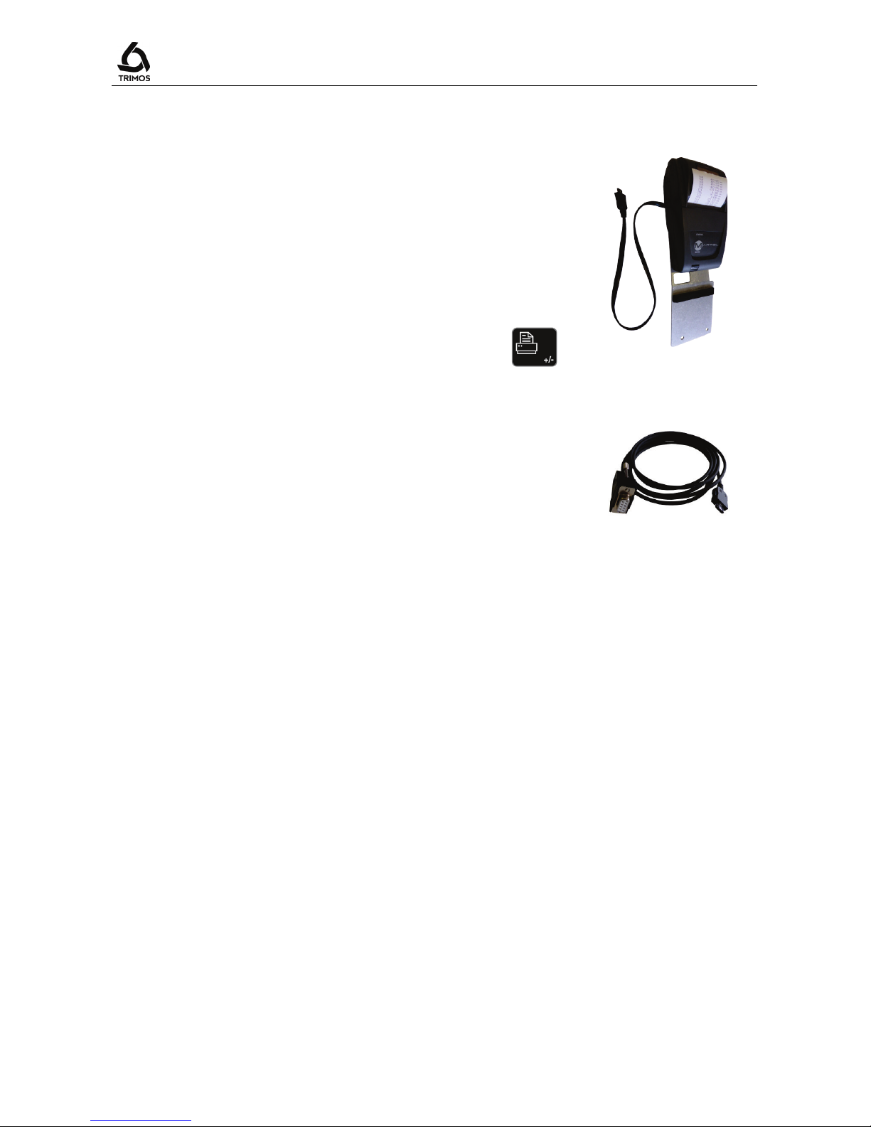
Connection to printer
Thermal printer TA-EL-032 (Ref. 756 0018), includes RS232
cable, charging unit and support.
Connection to PC
Cable TA-EL-112 (réf. 333 0 0104)
Compatible with all RS232 software (WinDDE,
HyperTerminal, WinWedge etc.)
Data transfer
The data transfer is made by pressing the
Data Transfer
key
Format
The configuration of data format is made in the set-up menu
(§ 8).
Thermal Printer with support
and RS232cable
Cable RS232 for PC
750 50 0045 03 22
Page 25
V3 / V4
8. CONFIGURATION
Various parameters of the instrument can be configured,
Press the
Validation
key during 2 seconds to enter set-up
menu
A simple pressure on
Validation key
validates the choice
and allows passing on to the next menu.
Quitting the set-up mode is automatically made after
passing the last menu. It is however possible to quit at any
moment by pressing the
Validation key
during 2 seconds.
> 2 s
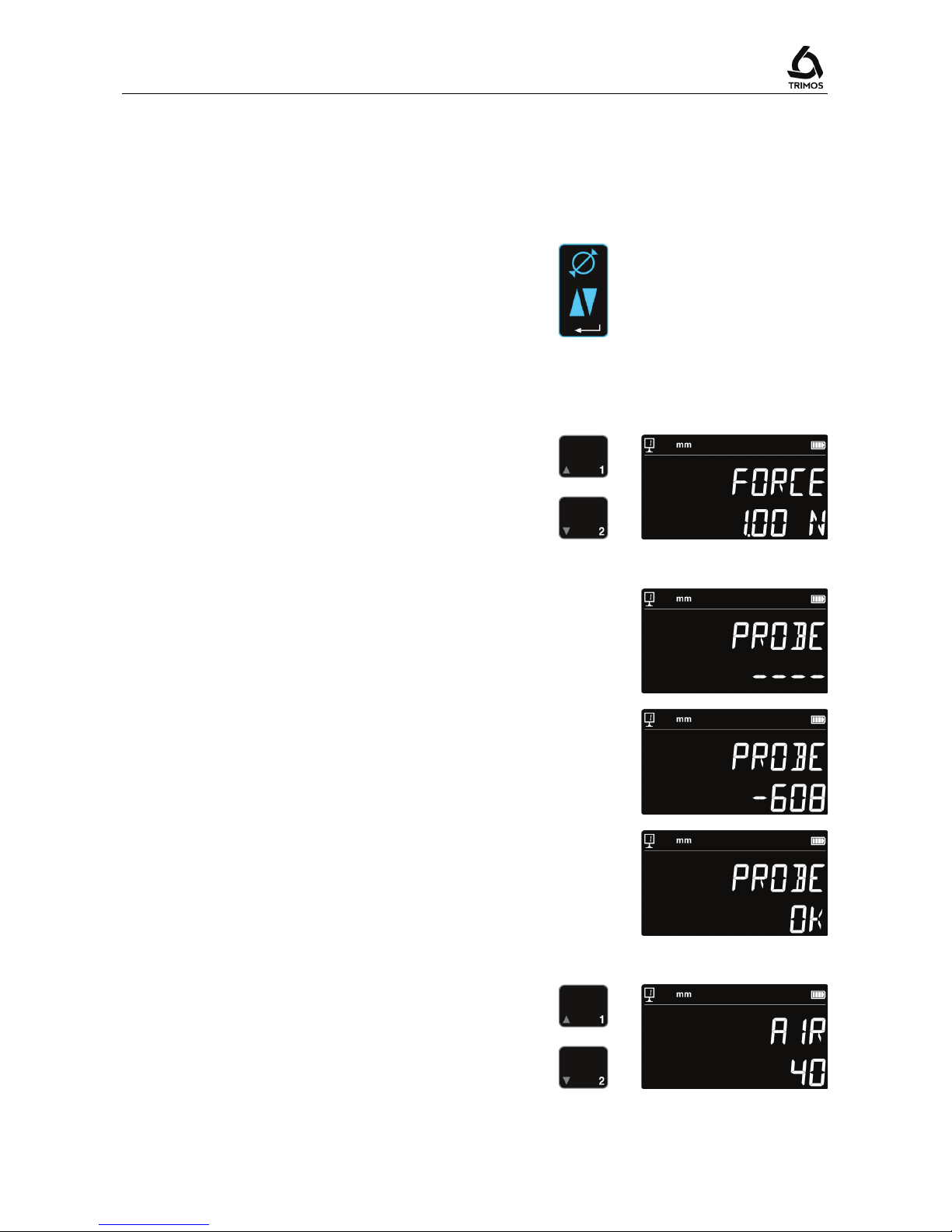
Measuring force adjustment
The measuring force can be electronically adjusted from
0.75 N to 1.5 N. To adjust, press the keys opposite.
Control of probe weight balancing
This function allows adjusting the balancing of the probe
weight.
a) Start-up display
b) As soon as a movement of the carriage is detected, a
numeric value corresponding to the position of the
double carriage is displayed.
c) The carriage is considered as balanced when OK is
displayed in neutral position. The balancing procedure is
described in §
0.
a)
b)
c)
Air cushion adjustment (V4)
The air flow of the pump can be adjusted according to the
quality of the work table with the help of the keys opposite.
750 50 0045 03 23
Page 26
User's Manual
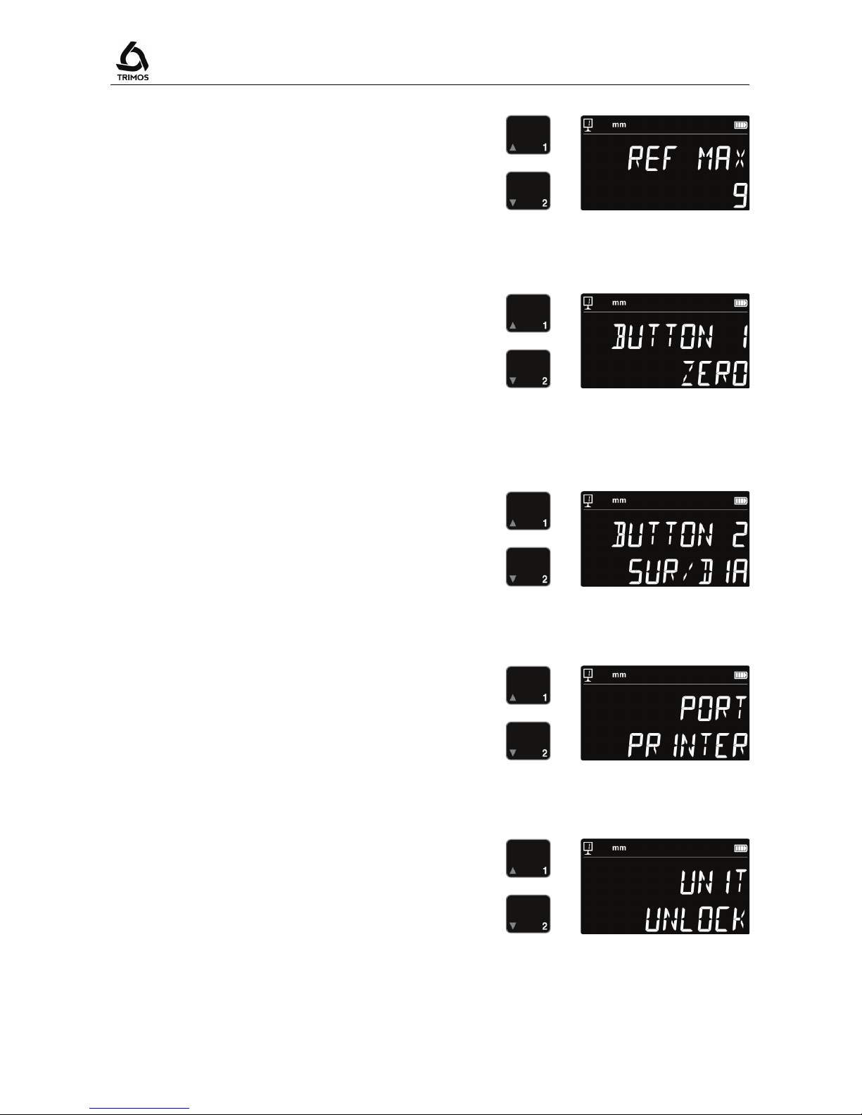
Number of references definition
The number of references available for the user can be
defined (1 ÷ 9). To do so, press keys opposite.
Programmable button 1 (V4)
Various functions can be attributed to programmable button
1:
- REF: change of reference
- PRESET: Preset
- ZERO: Zero setting (by default)
- PRINT: Data transfer (PRINT)
- SUR/DIA: Height/Diameter-centerline
Press the keys opposite to select the requested functions.
Programmable button 2 (V4)
Various functions can be attributed to programmable
button 2:
- REF: change of reference
- PRESET: Preset
- ZERO: Zero setting
- PRINT: Data transfer (PRINT)
- SUR/DIA: Height/Diameter-centerline (by default)
Press the keys opposite to select the requested functions.
Port RS232
The RS232 port can be configured in 2 ways :
- PRINTER: Data transfer to printer or PC
- OPTO RS: Communication according to Opto RS
standard
Press the keys opposite to select the requested functions.
Unit blocking
The active unit can be blocked. Therefore it will not be
possible to change it in work mode.
To block the function, select "LOCK" with the help of the
keys opposite. To release it, select "UNLOCK".
750 50 0045 03 24
Page 27
V3 / V4
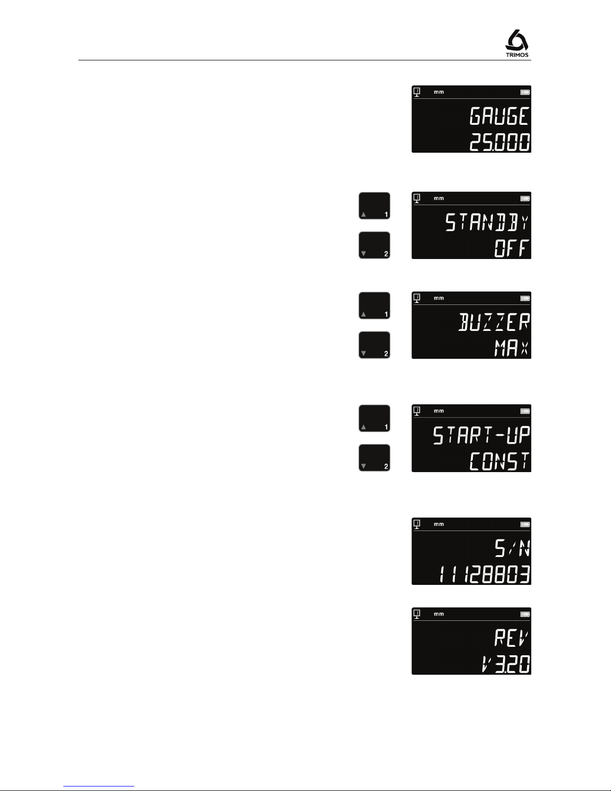
Size of reference gauge
If the measuring insert calibration has to be made with
another reference gauge than that delivered with the
instrument, the height of the gauge can be entered with the
help of the numeric keypad.
Standby mode
The instrument can switch to standby mode after a
predefined time (5 ÷ 120 min).
To define time before standby, press keys opposite. "OFF"
means that the instrument will never switch to standby
mode.
Acoustic signal level
The acoustic signal level can be adjusted with the keys
opposite.
Function after start-up
The function immediately available after starting-up of the
instrument can be selected with the keys opposite.
- CONST: Constant (by default)
- SUR: Height mode
- DIA: Diameter-centerline mode
- DELTA: Delta mode
- MAX: Max mode
- MIN: Min mode
Serial number
This function gives the serial number of the instrument.
Firmware version
This function gives the serial number of firmware.
750 50 0045 03 25
Page 28
User's Manual
9. APPLICATION AND ADJUSTMENTS
9.1 Probing
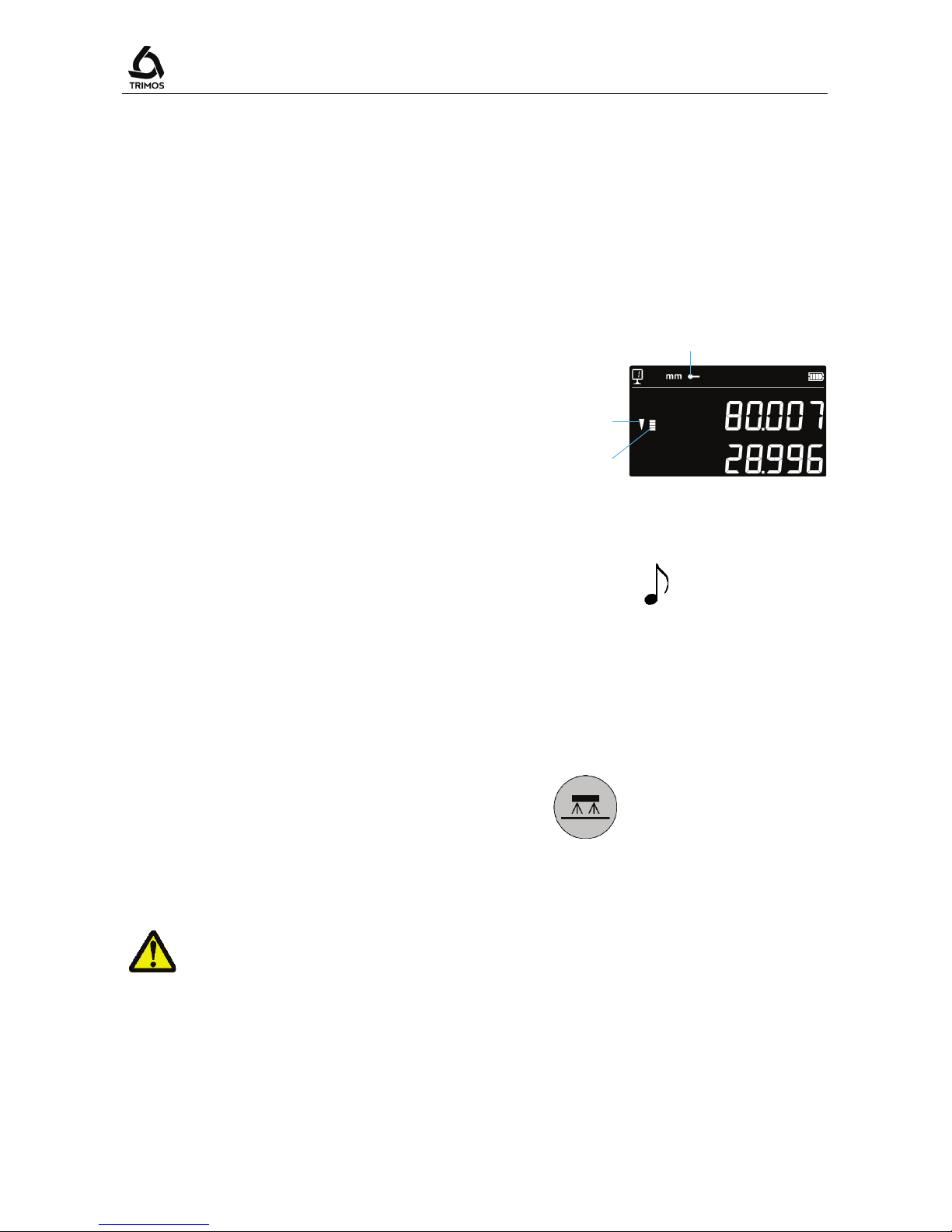
The measurement precision is directly linked to the quality of contact between the probe and the part to
be measured (⇒ probing). The instrument offers all tools allowing an optimal probing:
Probing indicator
Situated on the left of the measured value, it views the
probing zone (1).
If the probing zone has been passed, the display shows-.- - and an acoustic signal rings out as long as the indicator
remains out of the probing zone.
Probing direction indicators
Besides the acoustic signal, the measurement is visually
confirmed by the indicators of the probing direction (2) and
by the probing symbol (3).
Acoustic signal
An acoustic signal confirms a correct measurement probing
movement (measuring force set) and that the value has
been taken.
9.2 Air Cushion (V4)
The use of the air cushion facilitates the displacement of the
instrument on the granite plate. The activation of the air
cushion lifts the instrument at some µm. The air cushion is
not only used for the displacement of the instrument in
general but also when performing measurements (e.g.
diameters). The main application is found particularly in
industrial fields with large heavy parts. Small parts can be
moved without activating the air cushion. This allows to
significantly increase the autonomy of the instrument.
The air cushion force can be adjusted in the set-up menu (§
8).
When using the air cushion displacement for measurement procedures, all functions e.g. zero
or preset setting of the display should be done with air cushion to take into consideration the
lifting amount of the instrument.
Acoustic signal
1 2 3
750 50 0045 03 26
Page 29
V3 / V4
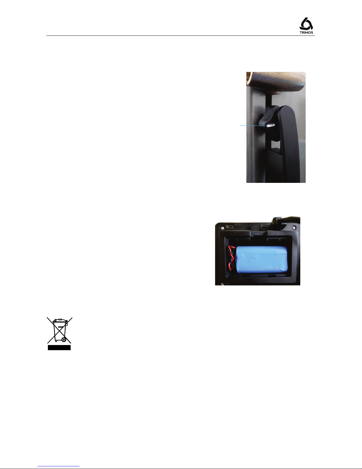
9.3 Adjustment of floating probe suspension balancing
In order to guarantee a constant measuring force in both
directions (upwards and downwards), it is necessary to
adjust the balancing of the floating probe suspension
according to the probe in use.
The adjustment button of the floating suspension (1) allows
compensating the weight of the probe in use.
A function facilitating the balancing can be found in the setup menu (§ 8).
9.4 Replacement of battery block
When the instrument autonomy is not sufficient anymore,
the battery block must be replaced :
1. Get a battery block from your TRIMOS agent (Trimos
réf.: 3704 0021).
2. Open the lid at the back of the display.
3. Remove the old battery block and replace it by the
new one (pay attention to the connector polarity).
4. Close the lid tightly.
5. Load the new batteries.
9.5 Recycling of electronic components
Disposal of Waste Electrical and Electronic Equipment (WEEE) applicable throughout
the European Union and other European countries with separate collection programs
This symbol, found on the product or its packaging, indicates that it should not be treated as
household waste. It should be handed over to an official collection point for the recycling of
electrical and electronic equipment. A correct recycling of this product will help to preserve
the environment and the natural resources. For more detailed information about the recycling
of this product, please contact your local authorities or your TRIMOS supplier.
1
750 50 0045 03 27
Page 30
User's Manual
9.6 Resetting of the instrument
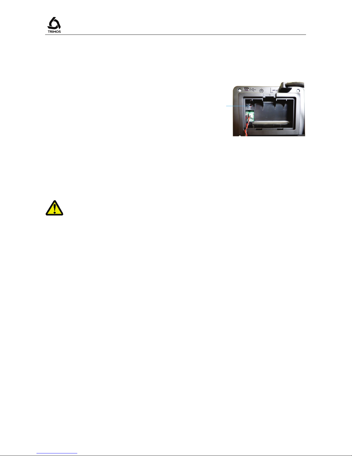
In case of blocking, it is possible to force the resetting of the
electronics. To do so, open the lid at the back of the display
and press the Reset button (1) with the tip of a pencil.
9.7 Cleaning
The plastic parts, the display unit as well as the painted parts of the instrument should be cleaned using a
slightly dampened (watered) fabric. Clean the air cushion pads using a clean fabric, slightly dampened
with alcohol.
The use of solvents such as acetone, white spirit, trichloethylene, petrol or others for
cleaning must absolutely be avoided!
10. AFTER SALES SERVICE
10.1 Complaints / repairs
In case of problems, please contact your local TRIMOS agent.
For any transport, use the original packing or an adequate one.
10.2 Agents
You can find the official TRIMOS agents list on the website www.trimos.ch
1
750 50 0045 03 28
Page 31
V3 / V4
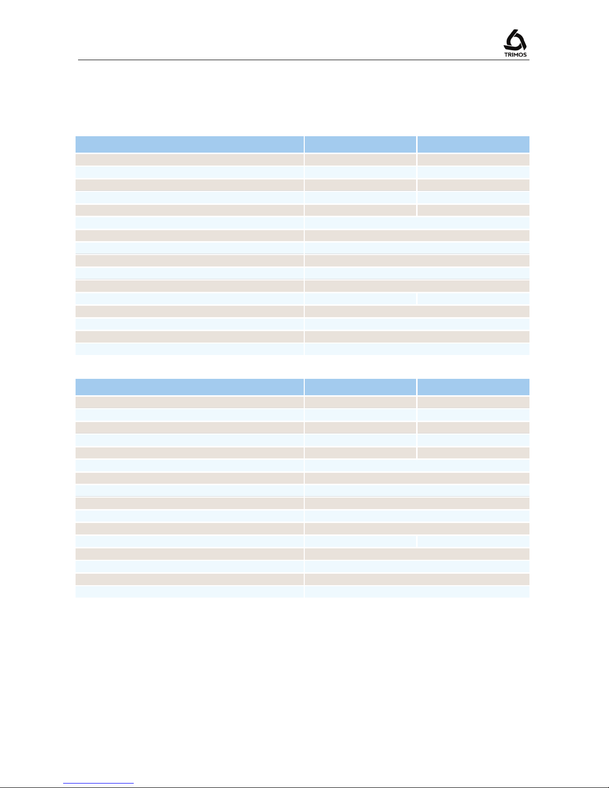
11. TECHNICAL SPECIFICATIONS
V3 400 700
Measuring range mm (in)
407 (16)
711 (28)
Application range mm (in)
508 (20)
812 (32)
Max. permissible errors, E
MPE
µm
7
8
Repeatability, R
MPE
µm
2 (Ø: 4)
2 (Ø: 4)
Overall squareness deviation (frontal), S
MPE
µm
10
15
Max. resolution mm (in)
0.001 (0.00005)
Measuring force N
0.75 ÷ 1.5
Autonomy h
40
Data output
USB / RS232
Air cushion
No
Protection grade of measuring system (CEI 60529)
IP67
Weight kg
21
24
Max. weight of measuring insert & holder g
400
Max. manual displacement speed m/s
1
Operational temperature °C
+10 .. +40
Storage temperature °C
-10 .. +40
V4 400 700
Measuring range mm (in)
407 (16)
711 (28)
Application range mm (in)
719 (28)
1023 (40)
Max. permissible errors, E
MPE
µm
5
7
Repeatability, R
MPE
µm
2 (Ø: 4)
2 (Ø: 4)
Overall squareness deviation (frontal), S
MPE
µm
10
15
Max. resolution mm (in)
0.001 (0.00005)
Measuring force N
0.75 ÷ 1.5
Autonomy h
40
Data output
USB / RS232
Air cushion
Yes
Protection grade of measuring system (CEI 60529)
IP67
Weight kg
21
24
Max. weight of measuring insert & holder g
400
Max. manual displacement speed m/s
1
Operational temperature °C
+10 .. +40
Storage temperature °C
-10 .. +40
Note:
The above values have been determined according to ISO 13225.
These are valid with the standard probe (TA-MI-101), at a temperature of 20 ± 0.5 °C and a relative humidity of 50 ±5%.
R
MPE
is defined as twice the standard deviation (2s) over 20 measurements.
750 50 0045 03 29
Page 32
User's Manual
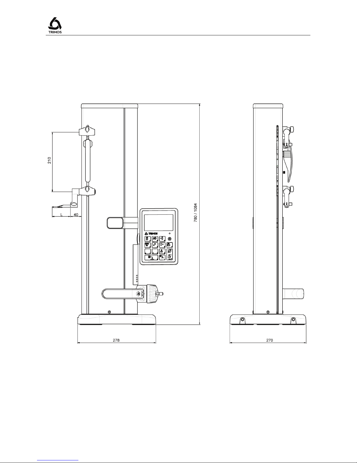
12. DIMENSIONS
L: depends on the measuring insert used
750 50 0045 03 30
 Loading...