

Page 1

www.trimond.com
TRIMOND™ HN440 ATX
MOTHERBOARD USER'S GUIDE
Page 2

Trademarks mentioned within this document are the
properties of their respective owners. Details available on
request.
Information contained in this document is subject to change
without notice and does not represent a commitment on the
part of Mitsubishi Electric.
No part of this manual may be reproduced or transmitted in
any form or by any means electronic or mechanical including
photocopying and recording, for any purpose, without the
express written permission of the publishers.
Published by:
Mitsubishi Electric Motherboard Division
3500 Parkside
Birmingham Business Park
Birmingham, England
B37 7YS
Copyright Mitsubishi Electric UK 1999
Page 3

HN440 USER’S GUIDE
SAFETY & REGULATORY NOTICES
Battery
This product contains a lithium battery.
Do not use a metal or other conductive tool to remove the
battery. If a short-circuit is made between its positive and
negative terminals the batter y ma y explode.
Replace a discharged battery with one of the same type;
another type may explode or ignite. Follow the instructions
contained in this User’s Guide to replace the battery. Dispose
of a discharged battery promptly and in accordance with the
battery manufacturer’s recommended instructions. Do not
recharge, disassemble or incinerate the discharged battery.
Keep away from children.
Thermal interface material
Thermal interface materials used between a heatsink and the
processor can cause skin irritation and stain clothing. Avoid
prolonged or repeated contact with skin. Wash thoroughly
with soap and water after handling. Avoid contact with eyes
and inhalation of fumes. Do not ingest.
Anti-static precautions
Warning
Static electricity can cause permanent damage to electronic
components. You should be aware of this risk, and take
precautions against the discharge of static electricity.
This product is at risk from static discharge because the
electronic components of the motherboard are exposed.
Memory modules and replacement processors are examples
of electrostatic sensitive devices (ESSDs).
All work that involves contact with the HN440 motherboard
should be done in an area completely free of static electricity.
We recommend using a Special Handling Area (SHA) as
defined by European Standard EN 100015-1: 1992. This
means that working surfaces, floor coverings and chairs must
be connected to a common earth reference point, and you
Safety & Regulatory Notices 3
Page 4

HN440 USER’S GUIDE
should wear an earthed wrist strap and anti-static clothing. It
is also a good idea to use an ionizer or humidifier to remove
static from the air.
Handle static-sensitive items with extreme care. Hold
components only by their edges, avoiding their electrical
contacts. In general, do not handle static-sensitive items
unnecessarily.
Keep all conductive material, and food and drink, away from
your work area and the motherboard.
Legalities
This product complies with the relevant clauses of the
following European Directives (and all subsequent
amendments):
Low Voltage Directive 73/23/EEC
EMC Directive 89/336/EEC
CE Marking Directive 93/68/EEC
Important
This product, when supplied, complies with the CE Marking
Directive and its legal requirements. Use only parts tested
and approved by Mitsubishi Electric’s Motherboard Division.
Standards
Safety
This product complies with the American Safety Standard
UL1950.
Electro-magnetic Compatibility
This product complies with the following European EMC
standards:
Emissions EN55022 Class B
Immunity EN50082-2
This product also complies with the following American
EMC standard: FCC Class B
4 Safety & Regulatory Notices
Page 5

HN440 USER’S GUIDE
FCC Compliance Statement
Note: This equipment has been tested and found to comply
with the limits for a Class B digital device, pursuant to part 15
of the FCC Rules. These limits are designed to provide
reasonable protection against harmful interference in a
residential installation. This equipment generates, uses and
can radiate radio frequency energy and, if not installed and
used in accordance with the instructions, may cause harmful
interference to radio communications. However, there is no
guarantee that interference will not occur in a particular
installation. If this equip ment does cause harmful interference
to radio or television reception, which can be determined by
turning the equipment off and on, the user is encouraged to
try to correct the interference by one or more of the following
measures:
Reorient or relocate the receiving antenna.
Increase the separation between the equipment and
receiver.
Connect the equipment into an outlet on a circuit
different to that to which the receiver is connected.
Consult the dealer or an experienced radio/TV
technician for help.
Important
You are cautioned that any change or modification to the
product not expressly approved by the manufacturer could
void the approvals held by this product.
Safety & Regulatory Notices 5
Page 6

HN440 USER’S GUIDE
CONTENTS
OVERVIEW 7
Item checklist 8
Key features 8
Motherboard layout diagram 10
Motherboard block diagram 12
INSTALLATION 13
Installation steps 14
Jumper settings 15
System memo r y (DI MM s) 17
Processor 19
Expansion cards 23
Internal connectors 26
External connectors 31
Connecting to AC power 32
Replacing the motherboard battery 34
BIOS SETUP 35
USING THE SUPPORT CD 39
GLOSSARY 40
6 Contents
Page 7

HN440 USER’S GUIDE
OVERVIEW
The name Mitsubishi Electric is known the world over for
quality, reliability and dependability. The Trimond™ HN440
“Hornet” ATX motherboard from Mitsubishi Electric
Motherboard Division continues this tradition, combining
innovative design with hi gh-quality components.
The HN440 is an ATX profile motherboard designed around
the use of Intel Celeron™, Pentium
processors. All three package variations are supported – SEPP
(Celeron™), SECC (Pentium
and Pentium
®
III).
®
®
II and Pentium® III
II) and SECC2 (Pentium® II
The motherboard is intended for use with a logic-controlled
“soft-switch” Power Supply Unit (PSU). Such a PSU is
needed for certain features of the motherboard, such as Wakeon-LAN and power-saving Suspend and Standby modes.
The HN440 has the following major build options:
Intel 440ZX or 440BX chipset
Audio system with joystick/MIDI support (440BX only)
Heceta II System Monitor
Note
The number of memory (DIMM) sockets is affected by these
build choices. Builds with 440ZX have two DIMM sockets;
builds with 440BX have three DIMM sockets.
Overview 7
Page 8

HN440 USER’S GUIDE
Item checklist
Check that your package is complete. If you discover
damaged or missing items, contact your Trimond™ supplier.
HN440 motherboard
HN440 User’s Guide (this book)
Support CD with BIOS and drivers
Ribbon cable for 3.5- and 5.25-inch diskette drives
Ribbon cable for master and slave IDE drives
Key features
Advanced processor support: Intel Pentium® III,
Pentium
®
II and Celeron™ processors at 233 MHz and above
in a Slot 1 connector with a Universal Retention Mechanism.
ATX form-factor: ATX 2.01 compliant (12.0 x 7.5 inches)
with standard fixing holes.
Intel AGPset: Either Intel 440ZX or 440BX PCI AGP
Controller (build option) plus PIIX4e Multifunction ISA
Bridge.
PC100 Memory Support: Either two (440ZX) or three
(440BX) DIMM sockets supporting Intel PC100/66compliant SDRAMs. PC100 modules are required when using
processors with a 100 MHz bus. Either PC66 or PC100
modules may be used with 66 MHz bus processors. See page
17 for more information.
Optional Audio: Available only for 440BX-based
motherboards. ESS Solo-1 PCI codec, Sound Blaster Pro
register-compatible. Features internal FM synthesiser, fivechannel input mixer and MPU401-compatible MIDI interface.
Supports external line-in, line-out and microphone
connectors. Supports internal CD-ROM stereo, line-in and
telephony (voice mail) via 4-pin ATAPI connectors.
8 Overview
Page 9

HN440 USER’S GUIDE
Peripheral ports: Two serial ports. One parallel port with bidirectional, EPP 1.9 and ECP (IEE1284) capability. Dual
Universal Serial Bus (USB) ports. PS/2-style mouse and
keyboard ports.
UltraDMA/33 IDE: The PIIX4e incorporates a dual IDE
Controller. Two motherboard connectors allow two devices
on each of two channels. Supports UltraDMA/33, Polled IO
Modes 3 and 4, and Bus Master IDE DMA Mode 2. Supports
Enhanced IDE and ATAPI devices.
Advanced Configuration & Power Interface: The PIIX4e
supports ACPI. Compatible with Microsoft/Intel PC97 and
PC98 Plug and Play standards. Support for a logic-controlled
“soft-switch” Power Supply Unit (PSU). Supports powersaving Suspend and Standby modes.
PCI & ISA Expansion Slots: One ISA slot, one shared
ISA/PCI slot and three PCI slots.
AGP 2X Slot: Supports either Accelerated Graphics Port 1X
(66 MHz) or 2X (133 MHz) modes. (There is no on-board
video controller.)
Wake-on-LAN: Motherboard connector for input from
network cards that support Wake-on-LAN technology.
System Management: Desktop Management Interface
(DMI) support in BIOS. Heceta II System Monitor (build
option) supports monitoring of fans, power rails (+12 V,
+5 V, +3.3 V, CPU Core, -12 V and 2.5 V), motherboard
surface temperature, and chassis intrusion.
Battery back-up: On-board lithium coin cell with 5 years
typical life.
Concurrent busses: The major busses (processor, memory,
PCI and AGP) all operate independently to achieve a high
degree of co ncurrency. Most CPU -DRAM and AGP -DRAM
transfers can occur concurrently with PCI transfers and so
consume no PCI bus bandwidth.
Overview 9
Page 10
HN440 USER’S GUIDE
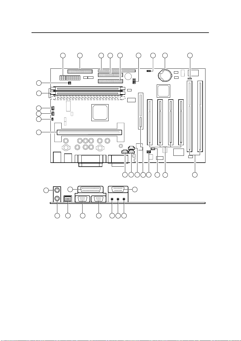
Motherboard layout diagram
1 2
23
22
21
20
19
18
A
F
C
B
D E
3
5
4
G
H
6
16
17
15
13
14
J
I
8
7
12
11
9
10
10 Overview
Page 11

1
Main Power
2
Diskette drive connector
3
Front panel header strip
4
Primary IDE connector
5
Secondary IDE connector
6
Processor speed jumpers
[J1]
7
CMOS memory clea r
jumper [PL1]
8
Lithium cell (CR2032)
9
BIOS write-protect jumper
[PL6]
10
ISA expansion slots
11
PCI expansion slots
12
Network card “Wake-onLAN” connector
13
Audio disable jumper &
digital volume control
[PL24]
14
AGP slot
15
ATAPI CD audio in
16
ATAPI audio line-in
17
ATAPI telephony
18
Slot 1 processor socket
19
Chassis intrusion switch
connector [PL14]
20
Processor fan connector
[PL15]
21
Chassis fan connector
[PL11]
22
DIMMs sockets (builddependent)
23
Hard switch power supply
jumper (Not supported)
A
Keyboard
B
Mouse
C
USB (Dual)
D
Serial port 1
E
Serial port 2
F
Parallel port
G
Line output
H
Line input
I
Microphone input
J
MIDI & joystick
HN440 USER’S GUIDE
Overview 11
Page 12
HN440 USER’S GUIDE
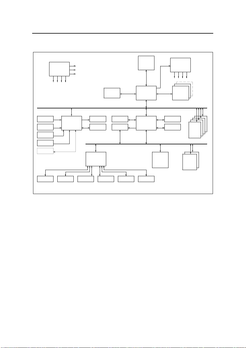
Motherboard block diagram
CLK Synth.
ICS9148-10
IC10
AGP CONN.
PCI BUS
Line In 1, PL26
Mic In, PL26
CD In, PL20
Line In 2, PL21
Telephony, PL22
Parallel Port, PL27 Floppy, PL3 COM1, PL27 COM2, PL27
AUDIO CODEC
SOLO1
IC23
Line Out, PL26
Midi/Joys, PL26
ISA BUS
Super I/O
FDC37C677
IC25
HN440 Block Diagram v2.0
PL10
Dual USB, PL28
BIOS, U1BIOS, U1
AGP BUS
CPU
SLOT1
IC18
SYSTEM BUS
CORE CHIPSET
443BX/ZX
IC13
PCI-ISA BRIDGE
PIIX4E
IC9
Mouse, PL29Keyboard, PL29
MEM BUS
Heceta II
IC17
CLK BUFF.
CLK BUFF.
ICS9179-12
ICS9179-12
DIMM Module
SDRAM
Prim. IDE, PL4
Sec. IDE, PL7
IC12
IC12
MM1-3
PCI SLOT
PL16-19
ISA SLOT
PL12,13
12 Overview
Page 13

HN440 USER’S GUIDE
INSTALLATION
Because of its standard ATX size and dimensions, the HN440
is capable of being installed in a variety of computer chassis.
For this reason, the installation instructions provided here do
not include any chassis-specific details such as how to mount
the motherboard or install hard disk drives. For t hese details,
you should consult the documentation supplied with your
chosen chassis, or the chassis manufacturer.
Warning
Always turn of the AC power supply and unplug the AC
power cord before carrying out any work inside the computer
chassis.
Anti-static precautions
Computer motherboards, processors, memory modules and
expansion cards are all vulnerable to static electricity. To
protect them against damage you should follow these
precautions:
Unplug the computer from the AC power supply.
If possible, always wear a grounded wrist-strap.
Otherwise, touch both your hands to a safely grounded
object or to a metal object such as the PSU case before
handling components.
Hold components by their edges and avoid touching any
circuitry, chips, pins or connectors.
Keep components in their anti-static packaging until
required. Place components on static-dissipative pads or
their anti-static packaging when separated from the
system.
Installation 13
Page 14

HN440 USER’S GUIDE
Installation steps
1. Review jumper settings.
2. Install memory modules.
3. Install the processor.
4. Install expansion cards.
5. Connect internal ribbon cables and leads, and the power
supply.
6. Connect external cables.
7. Connect AC power.
14 Installation
Page 15
HN440 USER’S GUIDE
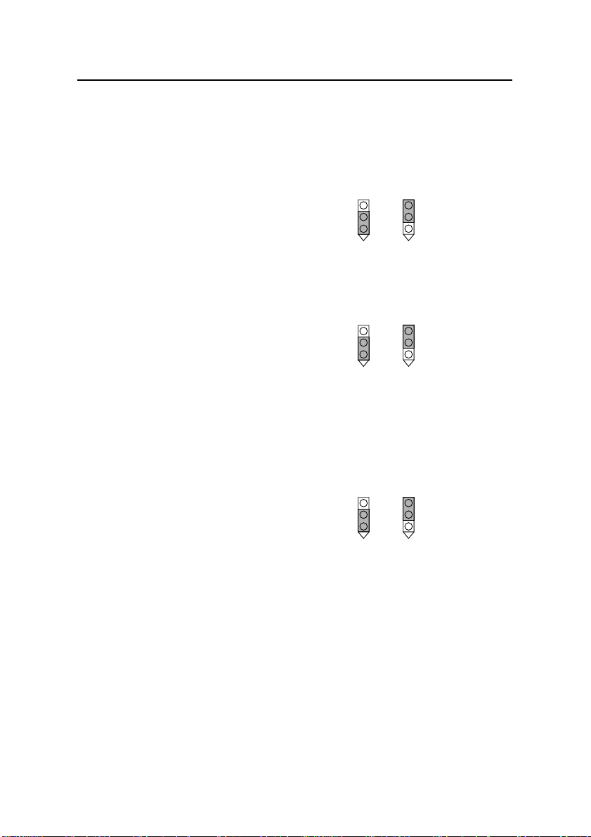
Jumper settings
PCI Audio codec Enable PL24 (item 13 on page 10)
This allows you to disable the optional ESS Solo-1 PCI
codec, if fitted.
1-2 Enable audio codec
2-3 Disable audio codec
BIOS Programming Enable PL6 (item 9 on page 10)
This allows you to update the BIOS firmware when
necessary.
1-2 Disable BIOS updates
2-3 Enable BIOS updates
Clear CMOS Memory PL1 (item 7 on page 10)
To clear configuration (CMOS) memory: disconnect the AC
power supply, move the jumper to position 2-3 and wait for a
few seconds, then return the jumper to position 1-2. The
jumper must be returned to the Normal position before po wer
is applied.
1-2 Normal operation
2-3 Clear CMOS
Motherboard
audio
enabled
BIOS
updates
disabled
Normal
operation
Motherboard
audio
disabled
BIOS
updates
enabled
Clear CMOS
Installation 15
Page 16
HN440 USER’S GUIDE
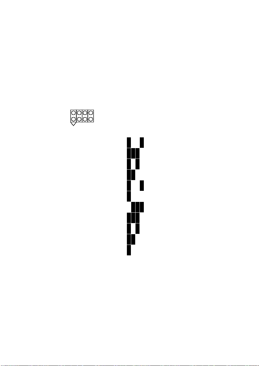
Processor speed jumpers J1 (item 6 on page 10)
These jumpers set the ratio of the processor’s internal clock
frequency (that is, the processor’s advertised speed), to the
external bus frequency (either 66 MHz or 100 MHz).
Note that many processors have fixed ratios, in which case
these jumper settings are ignored.
A B C D
Processor speed ABCD Ratio Bus frequency
233 MHz
266 MHz
300 MHz
333 MHz
350 MHz
366 MHz
400 MHz
400 MHz
450 MHz
500 MHz
550 MHz
ooooooo
ooooooo
ooooooo
ooooooo
ooooooo
ooooooo
ooooooo
ooooooo
ooooooo
ooooooo
ooooooo
o
3.5 66 MHz
o
4.0 66 MHz
o
4.5 66 MHz
o
5.0 66 MHz
o
3.5 100 MHz
o
5.5 66 MHz
o
6.0 66 MHz
o
4.0 100 MHz
o
4.5 100 MHz
o
5.0 100 MHz
o
5.5 100 MHz
16 Installation
Page 17
HN440 USER’S GUIDE
System memory (DIMMs)
The number of Dual In-line Memory Module (DIMM)
sockets on the HN440 motherboard depends on whether it is a
440BX or 440ZX build. The BX-build has three sockets, the
ZX-build has two. Also, Error Checking & Correcting (ECC)
is supported only by the BX-build.
The DIMM sockets accept 168-pin, 3.3 Volt, unbuffered
Synchronous Dynamic Random Access Memory (SDRAM)
modules of 16, 32, 64 or 128 MB (see “Choosing your
memory modules” below). The maximum possible total
memory is thus either 384 Mb (BX-build) or 256 Mb (ZXbuild). EDO (Extended Data Output) memory is not
supported.
Error Checking & Correcting (ECC)
To use the 440BX chipset’s ECC feature, you must use 72-bit
DIMM modules and make the proper settings within the
BIOS Setup utility.
Choosing your memory modules
The HN440 may fail to boot if non-compliant memory
modules are fitted. The SDRAM DIMMs must be:
Intel PC100 or PC66 compatible (see below)
168-pin
64-bit wide (72-bit with parity/ECC support)
3.3 Volt
Unbuffered
Non-EDO
PC100 modules are required when using processors with a
100 MHz bus. Either PC66 or PC100 modules may be used
with 66 MHz bus processors.
All modules must support Serial Presence Detect (SPD) to
allow the BIOS to determine the memory configu ra tion.
See the Approved Vendor List (AVL) on the Trimond™
website for details of DIMMs that h ave been tested with the
HN440.
Installation 17
Page 18
HN440 USER’S GUIDE
Installing DIMMs
1. Ensure that the system is turned off and that the AC
power cord is unplugged.
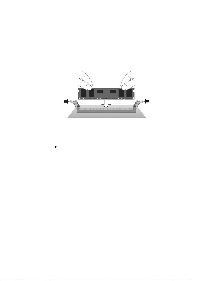
2. Insert the DIMM as shown. The DIMM will only fit one
way round because of the asymmetric notches along the
edge. Use the socket furthest from the processor
(marked MM1) first.
The DIMM is inserted vertically and held in
place by the clips at each end
Removing DIMMS
Press down on the tabs at both ends of the socket at the
same time. This releases the DIMM and lifts it partly out
of the socket.
18 Installation
Page 19
HN440 USER’S GUIDE
Processor
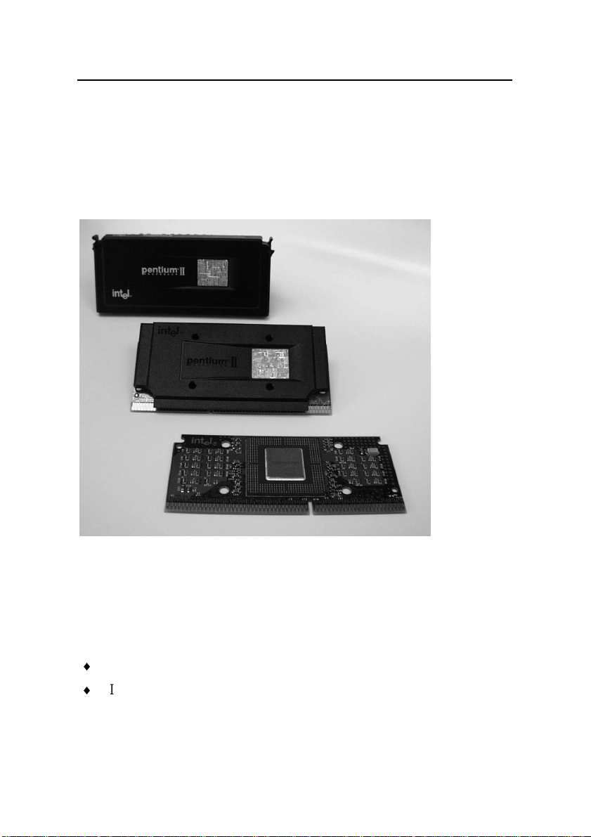
The HN440 motherboard has a Slot 1 connector for Intel
Celeron™, Pentium
All three package variations are supported – SEPP
(Celeron™), SECC (Pentium
and Pentium
®
®
II and Pentium® II processor packages.
®
II) and SECC2 (Pentium® II
III).
Examples of (from the top) SECC, SECC2 and SEPP processor
packages.
The motherboard uses a Universal Retention Mechanism
(URM) that accepts all supported processors.
To install the processor you must:
Attach the heatsink to the processor package
Insert the processor package into the Slot 1 connector
Installation 19
Page 20

HN440 USER’S GUIDE
Attaching the heatsink
So-called “boxed” or retail processor packages may already
have a fan heatsink attached. If not, you must obtain one.
There are many different types of heatsink, and the method of
attachment varies according to the manufacturer and the type
of processor package for which it is intended. The following
information is provided only as a general guide — follow
carefully any instructions provided with your particular
heatsink.
The recommended heatsinks are those with integral fans with
three-pin plugs that can be connected to the fan connector on
the motherboard (item 20 on page 10).
In all cases, make sure the heatsink is mounted tightly against
the processor package; otherwise, the processo r will overheat.
Most heatsinks have some kind of thermal interface material
applied to assure good heat transfer between the package and
the heatsink. Often, there is a plastic film over the thermal
interface material to protect it during shipping. If so, ensure
that this protective cover is peeled off before attaching the
heatsink.
Warning
Thermal interface materials can cause skin irritation and
stain clothing. Avoid prolonged or repeated contact with skin.
Wash thoroughly with soap and water after handling. Avoid
contact with eyes and inhalation of fumes. Do not ingest.
Celeron™ processor in a SEPP (Single Edge Processor
Package)
The SEPP package has four holes through the substrate by
which you can attach a heatsink. Typically, the heatsink is
secured to the processor side of the SEPP by a heatsink clip
pushed through from the other side of the SEPP.
1. Carefully insert all four legs of the heatsink clip through
the SEPP. Note that the heatsink clip must be on the
back (non-processor) side of the SEPP.
2. If necessary, peel away the protective film from the
thermal interface material on the heatsink.
20 Installation
Page 21

HN440 USER’S GUIDE
3. Fully engage one pair of heatsink clip legs with the
correspondi ng holes in the heatsink itse lf. Note that the
heatsink and substrate holes are slightly offset to ensure
good locking grip between the two.
4. Using a non-metallic tool, push the remaining pair of
clip legs into the heatsink. Do not b e nd or apply pressure
directly to the SEPP, and take care not to scratch the
surface of the SEPP substrate.
Pentium® II processor in a SECC (Single Edge Contact
Cartridge)
The SECC package is fully enclosed by a plastic cover and a
thermal plate. Depending on the manufacturer, the heatsink
may attach to the thermal plate by either metal spring-clips,
thermal tape or Rivscrews. Clip and tape fastenings are
straightforward to apply if you follow the heatsink
manufacturer’s instructions carefully. Rivscrews require
special tools to insert and remove; they are typically used for
securing heatsinks in industrial q uan tities.
Some SECC heatsinks require an additional support bracket.
The bracket has two pieces: a base that clips into the
motherboard and a removable bar than grips the heatsink,
locking it onto the base. The HN440 motherboard has two
mounting holes for such a bracket (located in front of the
processor slot) but the bracket itself is no t supplied nor fitted
as standard. Contact your Trimond™ supplier for more
details.
Note
The SECC packaging for Pentium® II processors is now being
superseded by the SECC2 packaging (see below).
Pentium® II or Pentium® III processor in a SECC2 (Single
Edge Contact Cartridge 2)
The SECC2 package features a plastic cover on one side and
the exposed substrate, with processor core, on the other.
There are four holes through the substrate/cover by which a
heatsink can be attached to the processor side. Typically, the
heatsink has four brass legs that protrude through these holes,
and is secured on the other side by a clip. Alternative ly, the
clip may protrude through the package to the heatsink.
Installation 21
Page 22

HN440 USER’S GUIDE
There are two versions of the Pentium® II SECC2 package:
PLGA (Plastic Land Grid Array) and the more recent OLGA
(Organic Land Grid Array). The arrangement of processorside components on the substrate is slightly different in each
case, which may necessitate different heatsinks. Ensure that
the heatsink is appropriate for your SECC2 package.
Inserting the processor
1. Ensure that the system is turned off and that the AC
power cord is unplugged.
2. Raise the support arms of the Universal Retention
Mechanism to their upright positions. (The arms of the
URM are folded down during shipment.)
3. With the heatsink facing in toward the motherboard,
insert the processor package into the URM. The support
arms guide the package so that it is positioned correctly
over the Slot 1 processor connector.
4. Push the processor package gently but firmly into the
Slot 1 connector until it is fully inserted. A SECC
package has two catches on the top that engage with the
URM support arms when the package is correctly
inserted – you will hear a click when this happens.
5. If your SECC package heatsink requires the additional
mechanical support bracket (mentioned above), insert
the removable locking bar. The bar slides over the
bottom fins of the heatsink and snaps onto the two outer
posts on the base. The two inner posts on the base act as
guides only.
6. Attach the fan lead to the processor fan connector
[PL15] on the motherboard (item 20 on page 10). If the
fan has only a two-pin plug, ensure it is connected
across pins 1 and 2.
Caution
The processor requires a continuous airflow when in
operation.
22 Installation
Page 23

HN440 USER’S GUIDE
Expansion cards
The HN440 ATX motherboard can accept three types of
expansion card:
ISA (Industry Standard Architecture)
PCI (Peripheral Component Interconnect)
AGP (Accelerated Graphics Port)
The motherboard has one ISA slot, one shared ISA/PCI slot,
and three PCI slots. (See the motherboard layout diagram on
page 10 for details.)
Before adding a card to your syste m you will need to know
whether it is ISA, PCI or AGP and possibly what system
resources it requires (interrupts, DMA channels and so on).
This information can usually be obtained from the
documentation or packaging that came with the card.
Installing an expansion card
1. Read carefully any documentation that came with your
card. If the card needs to be configured by the means of
jumpers or switches, check that it is correctly configured
before proceeding.
2. Ensure that the system is turned off and that the AC
power cord is unplugged before working inside the
computer’s chassis.
3. Remove the blanking plate at the rear of the chassis
corresponding to the slot in which you intend to install
the card. Typically, this plate is held in place by a small
screw.
4. Carefully align the card’s edge connector with the
chosen slot and press firmly into position.
5. Secure the card to the chassis (you will usually be able
to re-use the screw you removed at Step 3).
6. Connect any necessary signal cables to the card.
Installation 23
Page 24

HN440 USER’S GUIDE
Troubleshooting resource conflicts
If the card you have just installed uses scarce system
resources such as interrupts (IRQs), Direct Memory Access
channels (DMAs), or input/output (I/O) ports, o r has its own
on-board memory that must be “mapped” into the computer’s
unused Upper Memory Block (UMB) address space, there is a
possibility that it may come into confl ict wit h other expa nsio n
cards or devices on the motherboard that want to use the same
resources.
Conflict is more probable if the card is a so-called “legacy”
device; that is, one that does not support “Plug and Play”.
Plug and Play
Plug and Play (PnP) allows the intelligent, automatic
assignment of system resources to mini mise the possibilit y of
conflict. This assignment may be done by the BIOS alone or
in co-operation with a PnP-aware operating system such as
Windows 95/98.
BIOS Setup includes an option called
which should be set to
you have a PnP-aware operating system. If in doubt, select
No
See the BIOS Setup chapter for details.
.
Yes
Plug and Play O/S
No
or
according to whether or not
Legacy cards
Most modern cards support Plug and Play. For those that do
not, you may ha ve to run the BIOS Set up utility and reserve
or exclude the system resources used by the card (known as
“fixed” or “forced” resources). Once this has been done, PnPcompliant devices won’t attempt to use the same settings.
In extreme cases you may have to change the resources used
by the card, either by physically moving a jumper on the card
or by running a configuration utilit y provided with the card,
or both. Refer to the documentation or packaging that came
with the card for further information. An alternative strategy
would involve using the BI OS Setup uti lity to disab le unused
motherboard devices, and thereby free system resources for
use by the card.
24 Installation
Page 25

HN440 USER’S GUIDE
Troubleshooting in Windows 95/98
The Help systems in Windows 95 and Windows 98 include
Hardware Conflict Troubleshooters that you may find helpful.
If necessary, you can use Windows’ Control Panel to change
resource settings:
1. Click the Start button in the taskbar, then point to
Settings and click Control Panel.
2. Double-click on Syste m, then click the Device Ma nager
tab of the System Properties dialog.
3. Select the device whose resources you want to change,
then click Properties.
4. Click the Resources tab of the device’s Properties
dialog.
(If your device does no t ha ve a Reso urc es tab , eit her you
cannot change its resources or it isn't using any reso urce
settings.)
5. Click the resource you wa nt to c ha nge, un-check the Use
Automatic Settings box, then click Change Setting.
Tip
In some cases, you may see a Set Configuration
Manually button on the Resources tab. You may have to
click this button before you can change resource
settings.
Windows 98 also includes the Microsoft System Information
tool which can help you to diagno se resource con flic ts:
1. Click the Start button in the taskbar, then point to
Programs, Accessories, and System Tools, and then
click System Information.
2. Double-click on Hardware Resources.
Installation 25
Page 26

HN440 USER’S GUIDE
Internal connectors
The precise sequence in which you make internal connections
depends on the physical layout o f the chassis a nd the position
of the motherboard within it, as these determine the
accessibility of the various motherboard connectors.
After all internal connections have been made, close the
chassis.
Ribbon signal cables plug into their respective motherboard
connectors in only one orientation, to prevent incorrect
insertion. Also, the cables themselves are usually marked with
a red stripe corresponding to pin 1 of the connector. Press
firmly, but if the ribbon cable plug does not seem to fit it is
probably the wrong way round.
Diskette drive connector (item 2 on page 10). Intended for
the diskette (floppy) drive ribbon signal cable.
Primary/Secondary IDE connectors (items 4 and 5 on page
10). Typically, the primary connector is used for the system’s
hard disk drives and the secondary or removable-media drives
such as CD-ROM or tape.
Each connector can support two Enhanced IDE or ATAPI
devices: one Master and one Slave. Refer to your drive’s
documentation or packaging to find out how to configure it as
Master or Slave (typically by repositioning jumpers on the
drive). IDE ribbon cables should not be longer tha n 45 cm.
Processor and chassis fan connectors (items 20 and 21 on
page 10). These are designed for fans with 3-pin plugs.
Typically, the red or coloured wire is the +12 V line, the
white wire is ground.
The processor fan is normally always on but will stop
automatically when the system is in a power-saving Suspend
mode.
The chassis fan speed may be thermally controlled (according
to the processor’s temperature) if the system has a 100 MHzbus processor and a Heceta II System Monitor device fitted,
and if you are us ing an ACPI-aware o perating system. T his
can reduce fan noise in normal operation.
26 Installation
Page 27

HN440 USER’S GUIDE
Pin Description
1 Signal ground
2 +12 V DC fan drive voltage
3 Tachometric signal from fan
The tachometric signals are useful only on HN440 builds with
the Heceta II device.
CD audio, line-in and telephony connectors (items 15, 16
and 17 on page 10), for motherboard builds with Audio. The
CD audio connector allows the sound from music CDs played
in a CD-ROM drive to be mixed into the co mputer’s audio
system. The line-in and telephony connectors are respectively
intended for multimedia expansion cards and so-called
“speech modem” expansion cards with voice mail capability.
CD Audio and Line-in
Pin Description
1 Left audio input
2 Signal ground
3 Signal ground
4 Right audio input
Telephony
Pin Description
1 Input fro m mode m
2 Signal ground
3 Signal ground
4 Microphone output to modem
Wake-on-LAN connector (item 12 on page 10) for network
cards that support Wake-on-LAN technology. The
LAN
option in BIOS Setup must be enabled, and requires the
Wake On
use of a logic-controlled Power Supply Unit (PSU) with at
least 720 mA +5 V standby power.
Chassis intrusion switch co nnector (item 19 on page 10) for
motherboard builds with the Heceta II System Monitor.
Allows the connection of a signal cable from a microswitch
that can sense when the chassis is open or closed. The design
Installation 27
Page 28

HN440 USER’S GUIDE
assumes the switch is open when the chassis is closed. The
Heceta II can detect an intrusion even when AC power is
disconnected (the logic is powered from the backup battery).
Pin Description
1 Switch input
2 Signal ground
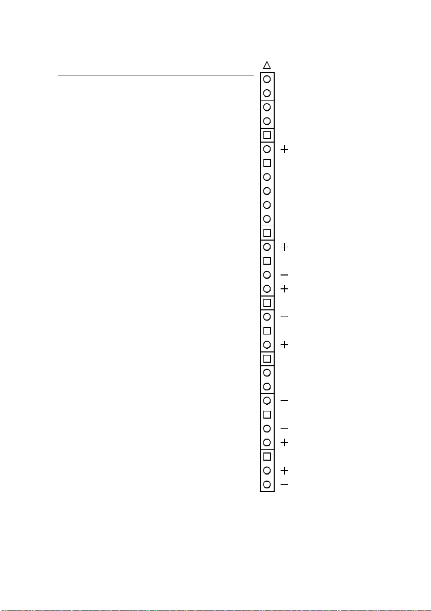
Front panel header strip (item 3 on page 10) providing a
range of connectors for various functions [pin numbers shown
in square brackets]:
Power button connector [1-2]. Connector for the lead
from the chassis Power button. Note that this requires
the use of a logic-controlled Power Supply Unit. The
button may be configured as a simple on/off button or as
a suspend/resume button i n the BIOS Setup utility. T he
suspend/ resume functionality also requires an ACPIaware operating system such as Windows 98.
Hard disk activity LED connector [13-16]. 4-pin
connector for the lead to the chassis’ hard disk drive
activity LED. Read and write activity on the primary
IDE interface cause the LED to light.
Power LED connector [18-20]. 3-pin connector for the
lead to the chassis’ power LED. A standard LED
illuminates when the computer is powered on. A twocolour LED can also indicate when the computer is in a
power-saving Suspend mode.
Reset button connector [22-23]. 2-pin connector for
the lead from the chassis’ Reset button. This button
allows you to reboot the system without cycling the
power supply.
Internal speaker connector [24-27]. 4-pin connector
for the lead to a chassis-mounted PC speaker.
Message LED connector [29-30]. Connector for a lead
to a LED that signals whether a message has been
received from a fax/modem. This functionality requires
an ACPI-aware operating system such as Windows 98.
28 Installation
Page 29
HN440 USER’S GUIDE
Pin Description
1 Power button signal (momentary)
2Ground
3 -Not used-
4 -Not used-
5 Key (pin removed)
6 -Not used-
7 Key (pin removed)
8 -Not used-
9 -Not used-
10 -Not used-
11 -Not used-
12 Key (pin removed)
13 Hard disk activity LED +
14 Key (pin removed)
15 Ground
16 Hard disk activity LED +
17 Key (pin removed)
18 Power LED –
19 Key (pin removed)
20 Power LED +
21 Key (pin removed)
22 Reset switch signal
23 Ground
24 Ground
25 Key (pin removed)
26 Ground
27 Internal speaker
28 Key (pin removed)
29 Message LED +
30 Message LED –
1
Power ON switch
Not Used
Key
Not Used
Key
Hard Disk LED
Key
Power LED
Key
Reset switch
Speaker
Message LED
30
Installation 29
Page 30

HN440 USER’S GUIDE
0Internal power connectors
Main power supply connector (item 1 on page 10). The
motherboard is intended to be used with a logic-controlled
“soft-switch” Power Supply Unit (PSU). Use a PSU that
supplies at least 30 mA on the +5 V stand by rail. For Wakeon-LAN to function the PSU must supply at least 72 0 mA.
Caution
Ensure that the devices fitted in your system do n ot overload
the +5 V standby rail, or permanent damage to the
motherboard may result.
30 Installation
Page 31
HN440 USER’S GUIDE
51
6
9
10101
13
1
25
14
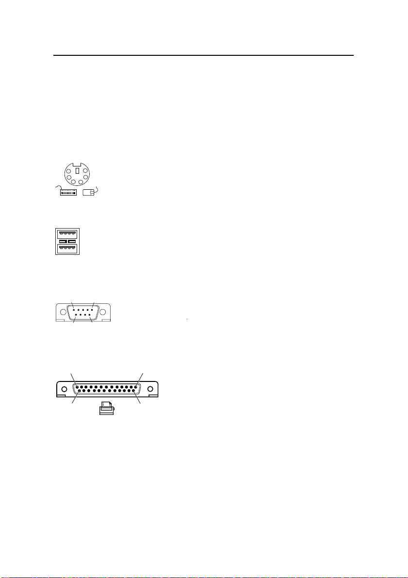
External connectors
The HN440 ATX has all the necessary external connectors or
ports for your PC system. Note that the audio and
joystick/MIDI ports are present only on motherboard builds
with Audio.
PS/2 keyboard and mouse ports (items A and B on page
10).
6
5
4213
Dual USB ports (item C on page 10).
1
4
Port 1
Port 0
1
4
Serial ports 1 and 2 (items D and E on page 10). 9-way Dtype connectors.
Parallel (printer) port (item F on page 10). 25-way D-type
connector.
Audio line-out, line-in, microphone sockets (items G, H and
I on page 10). 3.5 mm stereo jack sockets. The line-out socket
is also suitable for 32 • headphones. The microphone socket
provides phantom power to allow condenser-type
microphones to be used.
Joystick/MIDI port (item J on page 10). Requires an adapter
for use with MIDI devices.
Installation 31
Page 32

HN440 USER’S GUIDE
Connecting to AC power
Important
Any equipment that requires an AC power cord must be
earthed.
Use the following guidance to connect the components of the
system together. It is important that you take each step in the
order indicated.
1. Before connecting any components, ensure that the AC
power supply is switched off or disconnected, and that
the system unit, the monitor and any peripherals are
turned off.
2. Connect the component’s signal cables to their
respective ports on the system unit: keyboard, mouse,
monitor, audio (where appropriate) and any other
peripherals.
3. Connect the component’s power cords: monitor to
system unit (if the PSU has a pass-though AC port), and
system unit and any other peripherals to nearby,
grounded AC power outlets.
4. Turn on the system unit first, then the monitor, then
other peripherals.
Turning the system on and off
The following instructions apply if you are using a logiccontrolled PSU and an operating system that supports the
Advanced Configuration & Power Interface (ACPI):
To turn on the system, press the Power button. The
Power LED lights steadily green.
To suspend the system, press the Power button again.
(The Power LED may turn yellow, if a two-colour LED
is fitted.) Press the Power button once more to resume
the system.
To turn off the system, shut down the operating system.
If this is not possible, press and hold the Power button
for at least four seconds. The Power LED goes out.
32 Installation
Page 33

HN440 USER’S GUIDE
Wake On AC Connect
The BIOS Setup utility includes a
Wake On AC Connect
option which, if enabled, causes the s ystem to turn itself on
automatically when AC power is applied or when AC power
is restored after any break or interruption.
Note
If CMOS memory is cleared, perhaps because the
motherboard battery has become exhausted or has been
removed, the
Wake On AC Connect
option is ignored.
Installation 33
Page 34

HN440 USER’S GUIDE
Replacing the motherboard battery
The motherboard battery has a life of up to 5 years. If you
find that you have to reconfigure the computer every time you
turn it on, or the date and time seem to be significantly
incorrect, the battery is probably failing and needs to be
replaced.
The battery is a 3-volt lithium type (CR2032 or equivalent)
typically used in calculato rs, watches and ot her small, batterypowere d electronic items.
Warning
Do not use a metal or other conductive tool to remove the
battery. If a short-circuit is accidentally made between its
positive and negative terminals, the battery may explode.
1. Turn off the computer and unplug all power cords.
2. Using a non-conduc tive tool, release the la tch that hold s
the battery in place. The battery will pop up allowing
you to lift it out of the holder.
3. Taking care not to touch the top or bottom surface of the
new battery, pick up the replacement with the positive
(+) terminal upwards and press the battery into the
holder using a non-conductive tool.
4. Dispose of the old battery in accordance with the battery
manufacturer’s instructions.
When you next turn on the comp uter you will ha ve to run the
BIOS Setup utility to re-define the hard ware configuration.
Note
If you have a logic-controlled PSU, the battery is not used
while the system is powered off as long as the AC power
supply remains connected.
34 Installation
Page 35

HN440 USER’S GUIDE
BIOS SETUP
The BIOS (Basic Input/Output System) mediates between the
computer’s hardware and its software (principally the
operating system). The HN440 uses a BIOS from Phoenix
Technologies Ltd .
Setup is part of the BIOS firmware. It allows you to view and
alter a record of the computer’s hardware configuration held
in battery-backed memory.
To start the BIOS Setup utility
1. Turn on or restart your computer.
2. When the message
on the screen, press the
Press <F2> to enter Setup
F2
key.
appears
3. If you have previously defined a Supervisor password,
you are prompted for it before BIOS Setup starts.
Control keys
Use the keys listed in the legend bar at the bottom of the
BIOS Setup screen to make your selectio ns or exit t he current
menu (see table on next page).
Sub-menus are marked by a triangular pointer. To display a
sub-menu, use the arrow keys to move the cursor to the submenu you want, then press
Enter
.
Changeable fields are enclosed in square brackets. To select
an item, use the arrow keys to move the cursor to the field
you want. Then use the
Plus
(+) and
Minus
(–) keys to select
a value for that field.
Caution
The default BIOS settings may not be appropriate for your
particular system. Make a note of the current settings before
pressing
Exit
menu.
F9
or using the
Load Setup Defaults
option of the
BIOS Setup 35
Page 36

HN440 USER’S GUIDE
m
Press To
F1
Alt-H
or
View a general he lp topic . Press
the help window.
Esc
Left
or
Up
or
Plus
(+) or F6 or
Minus
Enter
Right
arrow Select a different menu.
Down
arrow Select fields on the current menu.
Spacebar
F5
(-) or
Exit the current menu.
Select the next value for the current field.
Select the previous value for the current field.
Make a selection from the menu bar or enter
a sub-menu.
Home
or
End
Move the cursor to the top or bottom of the
current menu.
Page Up
Page Down
or
Move the cursor to the next or p revious page
of the current menu.
F9
Restore the default settings for the fields on
the current menu.
F10
Save the change s you’ve mad e and exit fro
BIOS Setup.
Getting help in BIOS Setup
Esc
to close
You can at any time get ge neral help about the co ntrol keys
by pressing the
The help window on the right-hand side of each menu
displays help text for the currently-selected field. It changes
as you move the cursor from one field to another.
BIOS Setup’s menus
The exact details of the BIOS Setup utility’s menus and
options depend on the specific BIOS version used and may
vary with each new release. This section presents an overview
of the principal items that can be included.
Note
Incorrect settings may cause your system to malfunction.
36 BIOS Setup
F1
key.
Page 37

HN440 USER’S GUIDE
Main menu
Use this menu for basic system configuration, such as setting
the time and date, and identifying the diskette drives.
If necessary, sub-menus allow you to define the fundamental
characteristics of the system’s IDE drives, although these can
usually be determined auto matically. Further sub-menus may
allow you to configure memory caching and shadowing.
Boot menu
This menu allows you to alter the sequence in which the
BIOS firmware will look at various devices at boot time in
search of an operating system.
Advanced menu
Use this menu to configure certain advanced features of the
motherboard’s chipset.
Perhaps the most important item on this menu is that which
allows you to declare whether your operating system supports
Plug and Play (PnP).
The PCI Configuration sub-menu allows you to reserve
interrupts and upper memory block (UMB) regions for
“legacy” (non-PnP) expansion cards.
You can also fine-tune the configuration of your s ystem’s PCI
devices, and the serial and parallel ports.
Security menu
Use this menu to set User and Supervisor passwords, and the
Back-up and Virus Check reminders.
Power menu
Use this menu to specify your settings for power
management. Depending on yo ur system, you s hould be able
to set timeouts for overall power-saving Sta ndb y and S uspe nd
modes, and idle timeouts for individual devices such as hard
disk drives and the monitor. You can also configure the
Power button as a suspend/resume button instead of a simple
on/off button.
BIOS Setup 37
Page 38

HN440 USER’S GUIDE
This menu (or its sub-menus) should also include the Wake
On LAN and Wake On AC Connect options (see pages 27
and 33 for more information).
Note
If you use a operating system that supports the Advanced
Configuration & Power Interface (ACPI), some or all of these
settings may be overridden or rendered obsolete by choices
made within the operating system software.
Exit menu
This menu allows you to exit from the BIOS Setup utility,
with or without saving any changes you have made to the
BIOS settings. Usually, you would “save and exit”.
The Boot Menu
If you press
Esc
during the Power-On Self Test (POST), a
menu similar to the following appears:
Boot Menu
1. Diskette Drive
2. Removable Devices
3. Hard Disk Drive
4. ATAPI CD-ROM Drive
5. Network Boot
< Enter Setup >
This menu can be used to select the drive or device from
which to boot your system, for example a bootable CD-ROM,
without having to enter BIOS Setup. Si mply use the
Down
arrow keys to make a selection. This change will not b e
Up
and
permanent and the system’s boot device will revert to the
normal BIOS setting the next time you turn on your system.
Port 80 codes
The diagnostic “Port 80” codes issued by the BIOS during
POST are available from the Trimond™ website.
38 BIOS Setup
Page 39

HN440 USER’S GUIDE
USING THE SUPPORT CD
The Support CD contains BIOS updates and drivers for
contemporary (and some historical) motherboards from
Trimond™. The information is provided in a set of HTML
files that can be viewed with most modern web browsers
(Microsoft Internet Explorer 4 or later is recommended).
To use the CD, simply insert it in the computer’s CD-ROM
drive and use your browser to open the
root of the CD.
index.html
file in the
Using the Support CD 39
Page 40

HN440 USER’S GUIDE
GLOSSARY
Accelerated Graphics Port (AGP). A bus specification that
enables 3-D graphics to display quickly. The interface uses
the computer’s main memory for refreshing the monitor
image and to support the processing required for 3-D image
display. When not being used for accelerated graphics, main
memory is restored to use by the operating system or other
applications.
ACPI (Advanced Configuration & Power Interface). ACPI
defines a flexible and abstract hardware interface that
provides a standard way to integrate power management
features throughout a computer system, including hardware,
operating system, and application so ftware. In additio n, ACPI
provides a generic system event mechanism for Plug and Play
(q.v.) and an operating-system-independent interface for
configuration control. Windows 98 is an example of an ACPIaware operating system.
ATAPI (Advanced Technology Attachment Packet
Interface). An interface for removable-media drives. ATAPI
is part of the Enhanced Integrated Drive Electronics (EIDE)
interface, also known as ATA-2.
ATX. ATX is an industry-wide open specification for
motherboard layout and placement. ATX improves
motherboard design by allowing space for more full-length
expansion cards. A double-height aperture is specified for the
rear of the chassis, allowing a greater variety of peripheral
ports. ATX-based computers are also easier to cool.
codec (coder/decoder). In this context, an audio signal
analogue-to-digital, digital-to-analogue coder/decoder.
DIMM (Dual In-line Memory Module). A DIMM is a
circuit board containing memory chips which plugs into a
computer’s motherboard by a row of contacts on the DIMM’s
lower edge.
DMI (Desktop Management Interface). DMI is an industrystandard interface for keeping track of and monitoring the
status of components in a network of computers.
40 Glossary
Page 41

HN440 USER’S GUIDE
EIDE (Enhanced Integrated Drive Electronics). A standa r d
electronic interface for mass storage drives. EIDE’s
enhancements to the earlier IDE interface made it possible to
address hard disks larger than 528 Mbytes. EIDE also
provides faster access to the hard drive, support for Direct
Memory Access (DMA), and support for removable-media
drives (see ATAPI).
ECC (Error Checking & Correcting). A method of
detecting — and where possible correcting automatically —
errors in data that is being read or transmitted (in this conte xt,
to or from memory).
EPP/ECP (Enhanced Parallel Port/Extended Capability
Port). EPP/ECP is a standard signalling method for bi-
directional parallel communication between a computer and
peripheral devices, that offers the potential for much higher
rates of data transfer than the original parallel signalling
methods. EPP is for non-printer peripherals. ECP is for
printers and scanners. EPP/ECP are part of IEEE Standard
1284.
ISA (Industry Standard Architecture). ISA is a standard
bus architecture associated with the original IBM AT
motherboard. Although superseded technologically, many
expansion cards continue to use it.
logic-controlled Power Supply Unit (PSU). Al so known a s
a “soft-switch” PSU. A PSU that is controlled by a
combination of firmware/software and which is capable of
supplying current to a +5 V standby rail. Such a PSU
facilitates sophisticated power-saving modes, and features
such as Wake-on-LAN (q.v.). The system’s Power button is
connected to the motherboard rather than providing a direct
mechanical coupling to the PSU itself. See also ACPI.
OLGA. See SECC2.
PC66, PC100. Specifications from Intel for SDRAM (see
below) designed to operate at 66 MHz and 100 MHz
respectively.
PCI (Peripheral Component Interconnect). PCI is an
interconnection system between a microprocessor and
attached devices, including motherboard devices and
Glossary 41
Page 42

HN440 USER’S GUIDE
expansion cards. Originally designed by Intel as a local bus,
PCI is now relatively independent of microprocessor design.
PLGA. See SECC2.
Plug and Play (PnP). Plug and Play is both a design
philosophy and a set of computer architecture specifications.
The aim of PnP is to design intelligence i nto the computer to
handle installation and configuration tasks without user
intervention. The system itself determines the optimal
configuration, and applications automatically adjust to take
full advantage of the new configuration. PnP requires a PnPaware BIOS, operating system and devices (which can
include expansion cards and motherboard devices). The more
recent ACPI specification (q.v.) extends the functionality of
PnP-aware operating systems.
Rivscrew™. A proprietary fastening that combines the speed
of placement of a rivet with the ease of removal of a screw.
Requires special tools to insert and remove.
SDRAM (Synchronous Dynamic Random Access
Memory). A generic na me for variou s kinds of memory tha t
are synchronised with the clock speed for which the processor
is optimised. This tends to increase t he number o f instructions
that the processor can perform in a given time. The speed of
SDRAM is rated in MHz rather than in nanoseconds.
SECC (Single Edge Contact Cartridge). Packaging used for
original Pentium
enclosed in a plastic cover with thermal plate. Gradually
superseded by SECC2 packaging.
SECC2. Packaging used for later Pentium
III processors. Has a plastic cover on one side only. The
Pentium
Land Grid Array) and the more recent OLGA (Organic Land
Grid Array).
SEPP (Single Edge Processor Package). Packaging used for
Celeron™ processors.
®
II processors. The substrate is entirely
®
II and Pentium
®
II SECC2 package has two variants: PLGA (Plastic
®
UltraDMA/33. A protocol for transferring data between a
hard disk drive and the computer’s memory. The Ultra
DMA/33 protocol transfers data in burst mode at a rate of
33.3 megabytes per second, twice as fast as the previous
Direct Memory Access (DMA) interface.
42 Glossary
Page 43

HN440 USER’S GUIDE
Universal Retention Mechanism (URM). A plastic support
for Intel processors in Slot 1 connectors. Supports SECC,
SECC2 ad SEPP packaging.
USB (Universal Serial Bus). An interface/device standard
for computer peripherals. With USB, a new device can be
attached without having to turn off the computer. USB
supports a data speed of 12 megabits per second, and can also
supply DC power to certain devices.
Wake-On-LAN. Pr ovides the capability to remotely poweron a networked computer simply by sendi ng it a Wake-OnLAN packet. Wake-on-LAN support must be provided by the
motherboard, BIOS, network adapter, operating system and
client software, plus a logic-controlled PSU capable of
delivering at least 720 mA on the +5 V standby rail.
Glossary 43
 Loading...