

Page 1
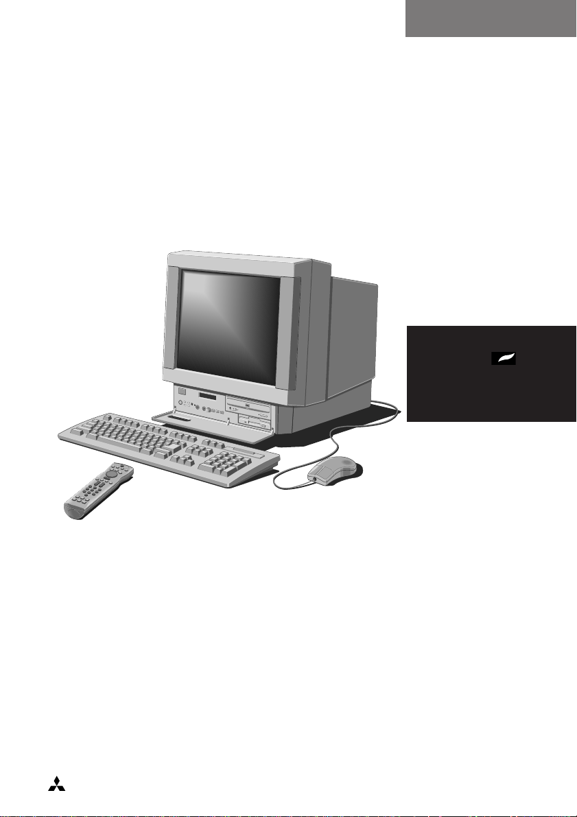
OWNER’S HANDBOOK
COMPACT
MS 530
apricot
MITSUBISHI ELECTRIC
Page 2

OWNER’S HANDBOOK
Page 3

Intel is a registered trademark, and Intel Pentium and OverDrive are trademarks
of Intel Corporation.
Microsoft® and Windows® 95 are registered trademarks of Microsoft in the
US and other countries.
Information contained in this document is subject to change without notice and
does not represent a commitment on the part of Apricot Computers Limited.
Any software described in this manual is furnished under a license agreement.
The software may be used or copied only in accordance with the terms of this
agreement. It is against the law to copy any disk supplied for any purpose other
than the purchaser’s personal use.
All rights reserved; no use or disclosure without written consent.
Copyright © Apricot Computers Limited 1995
Published by
Apricot Computers Limited
3500 Parkside
Birmingham Business Park
Birmingham B37 7YS
MITSUBISHI ELECTRIC
Printed in the United Kingdom
Part No. 15535331
Revision 01
Page 4

Safety and Regulatory Notices
Read the separate Power Connection Guide before using the computer for the first time.
The computer uses a safety ground and must be earthed. The system unit
AC power cord is its ‘disconnect device’. Ensure that the system unit is
positioned close to the AC power outlet and that the plug is easily
accessible. The power cord packed with the computer complies with the
safety standards applicable in the country in which it is first sold. Use only
this power cord. Do not substitute a power cord from any other equipment.
It is imperative that the system unit is set to the correct voltage range before
use. If not, the machine may be irreparably damaged.
To prevent fire and electric shock, do not expose any part of the computer
to rain or moisture.
When positioning the system unit, monitor and keyboard, take into account
any local or national regulations relating to ergonomic requirements.
Microphone, headphone and speaker cables should be less than 2 metres long.
Warning: This product contains a replaceable lithium battery. Do not use a
metal or other conductive implement to remove the battery. If a short-circuit is
accidentally made between its positive and negative terminals, the battery
may explode. Replace a discharged battery with one of the same type; another type
may explode or ignite. Dispose of the battery in accordance with the manufacturer's
recommended instructions. Do not attempt to recharge, disassemble or incinerate.
Keep away from children.
SAFETY & REGULATORY NOTICES
Any CD-ROM drive fitted in this system is classified as a CLASS 1 LASER
PRODUCT according to IEC825 Radiation Safety of Laser Products (Equipment
Classification: Requirements and User's Guide). The CLASS 1 LASER PRODUCT label is
located on the under side of the system unit.
SAFETY/1
Page 5

SAFETY & REGULATORY NOTICES
Use the CD-ROM drive only as described in this manual. Failure to do so
may result in exposure to hazardous radiation. Refer to the labels on the
computer to establish which of the following applies.
E.E.C.
This equipment complies with the relevant clauses of following European
directives:
89/336/EEC and 73/23/EEC, and is able to bear the CE mark.
Radio and television interference
The computer described in this manual generates and uses radio frequency
energy for its operation. If it is not installed and used properly, in strict
accordance with the manual, it may cause interference with radio and
television reception.
SAFETY/2
Page 6

CONTENTS
1 Introducing your computer
Your multimedia computer 1/2
Pictorial guides 1/4
2 Using your Computer
Using the front bezel controls 2/2
Using the infra-red remote control 2/5
3 Using the System Drives
Using the 3.5” diskette drive 3/2
Using the CD-ROM drive 3/4
Using the hard disk 3/6
4 The Multimedia Applications
The Infra-red Remote Control 4/2
The Apricot TV/Teletext Application (Optional) 4/3
The Apricot Message Centre application 4/4
The Apricot Media Manager Application 4/5
The Apricot Entertainment Centre Application 4/7
The Apricot Power Manager Application 4/8
The Radio application (Optional) 4/9
5 System Upgrades
Adding more system memory 5/2
Adding more cache memory 5/4
Adding more video memory 5/6
Upgrading the hard disk drive 5/8
Upgrading the processor 5/11
6 Expansion Cards
Configuring the card 6/3
Installing the card 6/8
MS 530 OWNER’S HANDBOOK I
Page 7

7 Maintaining and Transporting
Cleaning the computer 7/2
Transporting the computer 7/4
8 Troubleshooting
Problems when starting 8/2
Restoring the software 8/3
Troubleshooting checklist 8/3
The system’s disk drives 8/5
A Inside the System Unit
Anti-static precautions A/2
Opening the system unit A/3
The components inside your computer A/5
Board layout A/6
Jumper configurations A/7
Replacing the CMOS battery A/9
B System BIOS and Setup
Entering setup B/2
Control keys B/2
If setup runs on its own B/3
Opening screen B/4
Sub-menu pages B/5
Error messages B/12
C Technical Information
Specifications C/2
Physical characteristics C/4
Port characteristics C/5
II MS 530 OWNER’S HANDBOOK
Page 8

Introducing your Computer
1 INTRODUCING YOUR COMPUTER
This chapter gives you a quick tour of your Apricot multimedia computer.
It details the various features of the computer and contains pictorial
guides to help you identify the various parts of the machine.
This guide assumes that your computer is already set up and
ready for use. If you have yet to get your computer up and
running, please refer to the “Quick Start Up Guide” before
you read any further.
Warning
Read the separate Power Connection Guide before using the computer for the
first time.
MS 530 OWNER’S HANDBOOK 1/1
Page 9

Introducing your Computer
Your Multimedia Computer
Welcome to your MS 530 system! An all-in-one entertainment
centre which combines sound and vision with sophisticated
computing facilities.
The PC can be instantly transformed into a TV/ Teletext set with
additional facilities to capture, store and edit images as well as
providing the opportunity to view CDi titles and Photo CDs.
It can also be turned into an audio centre by tuning into the radio or
by playing your favourite audio CDs in the CD drive provided. The
CD drive gives you access to a whole host of sophisticated educational,
professional and games software.
The infra-red remote control provides you with a familiar userfriendly interface allowing you to switch from one activity to
another at the touch of a button.
All in all, your MS 530 multimedia system is a “complete” system
offering you the very latest in computer technology.
Standard Features
The standard features of the Apricot MS 530 multimedia system include:
• Integral all-in-one chassis with a slide-out LPX cage.
• Intel Pentium system processor with upgrade capability.
Standard 8 Mbytes of motherboard random access memory (RAM),
•
upgradeable to 64 Mbytes by the use of single in-line memory
modules (SIMMs).
Optional second level system memory cache (at least 256 Kbytes).
•
BIOS Setup configuration utility in read-only memory (ROM).
•
• Full power management.
Optional TV with Teletext support and operation.
•
1/2 MS 530 OWNER’S HANDBOOK
Page 10

• High quality 17” tube.
• Infra-red remote control with fully integrated two button mouse.
• Optional radio card.
• On-board high performance PCI bus video based on a Cirrus
Logic GD543x controller, equipped with at least 1 Mbytes of
video RAM, upgradeable to 2 Mbytes.
• Dual PCI Integrated Drive Electronics (IDE) hard disk drive
interface with an ATA-PI CD-ROM drive included as standard.
• Five expansion card slots.
• 1.44 Mbytes 3.5" diskette drive and 3.5" hard disk drive.
Energy-efficient features
All models in the range comply with the requirements of the US
Environmental Protection Agency’s “Energy Star” programme for
energy-efficient computers. These models support:
Introducing your Computer
• System Management Mode (SMM) of processors.
• Operating systems and applications that use the Intel/Microsoft
Advanced Power Management (APM) interface standard.
VESA BIOS Extensions for Power Management (VBE/PM), for
•
use with energy-efficient monitors that support Display Power
Management Signalling (DPMS).
If the computer is left unattended for a certain amount of time
(defined in the BIOS settings) the computer will enter a low power
mode. The screen will blank, and some of the computer’s components
will slow down. Do not worry! This is meant to happen. Pressing
any of the keys on the keyboard or moving the mouse should restart
the computer in full power mode.
MS 530 OWNER’S HANDBOOK 1/3
Page 11

Introducing your Computer
Further detailed information can be found in the Power Management
Help file provided with the system which can be found in the
Apricot Folder.
Pictorial Guides
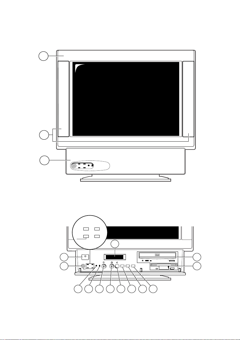
Front View:
1. Monitor
2. Speakers
3. Front Control Panel (Drops down to reveal further features).
Front Control Panel:
1. Power switch
2. Standby button
3. LED indicators for the states shown.
4. Infra-red remote sensor
5. Built-in microphone
6. Microphone socket
7. Headphone socket
8. Volume control button
9. Menu button
10. Decrement (-) button
11. Increment (+) button
12. LCD control function display
13. 3.5” floppy disk drive
14. CD-ROM drive
1/4 MS 530 OWNER’S HANDBOOK
Page 12
Front View
POWER MESSAGE
STANDBY HD
POWER
MENU
+
_
COMPACT
1
2
12
4 5 6 7 8 9 10
11
POWER MESSAGE
STANDBY HD
3
14
13
1
2
Introducing your Computer
3
Front Control Panel
POWER
_
MENU
+
COMPACT
MS 530 OWNER’S HANDBOOK 1/5
Page 13
Introducing your Computer
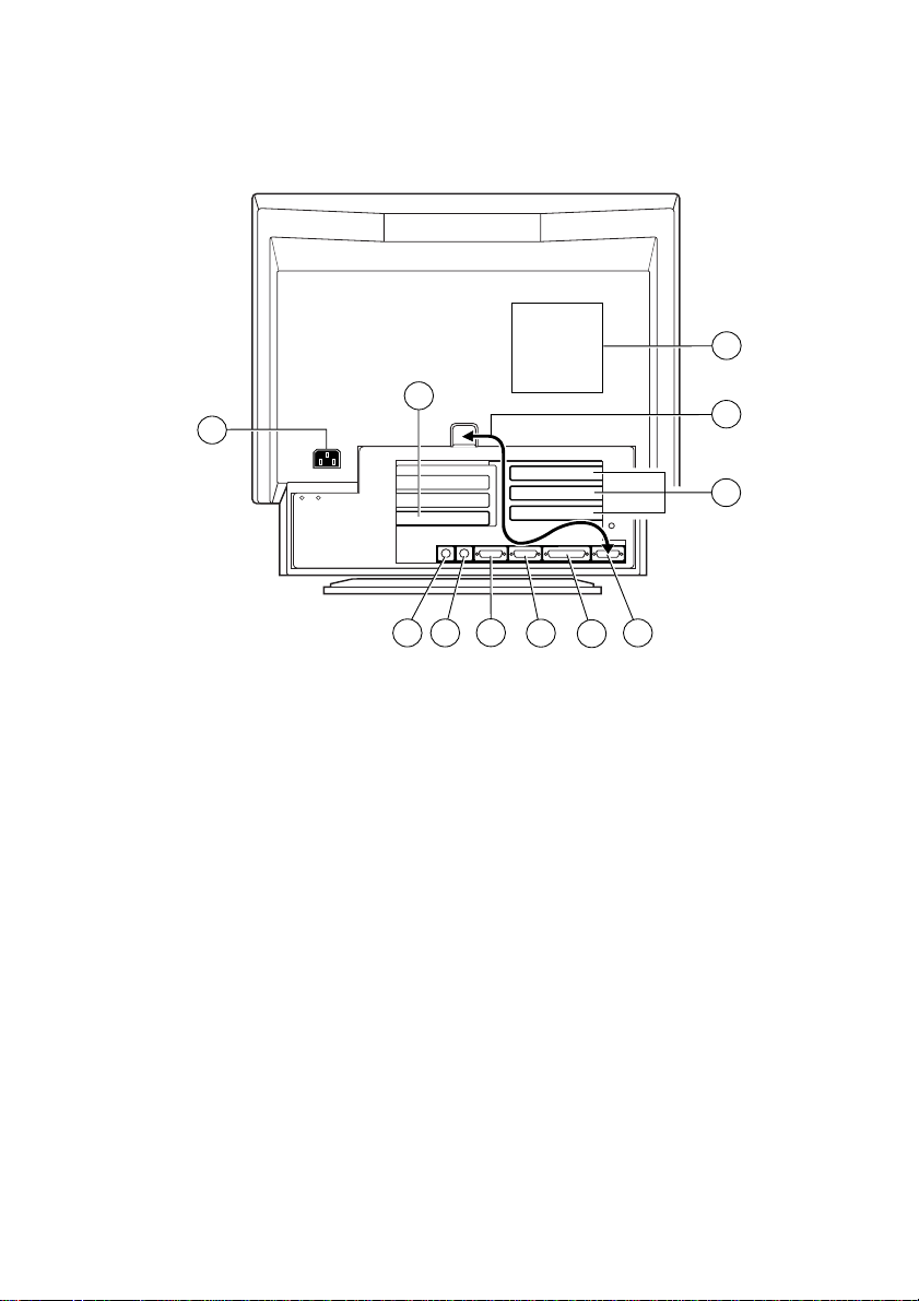
Rear View:
11
1
1. AC Power Inlet
2. Keyboard port
3. Mouse port
4. Serial port (COM 1)
5. Serial port (COM 2)
6. Parallel/printer port
7. Monitor connection
8. Expansion card slots
9. Audio external connectors
9
2 3
10
8
4
5
7
6
10. Monitor lead (which connects to 7)
11. System fan vents
1/6 MS 530 OWNER’S HANDBOOK
Page 14

Using your Computer
2 USING YOUR COMPUTER
This chapter contains all you need to know in order to start working
with your computer quickly. It gives you detailed instructions on
how to access and use the various features of the system.
Warning
Read the separate Power Connection Guide before using the computer for the
first time.
MS 530 OWNER’S HANDBOOK 2/1
Page 15
Using your Computer
POWER MESSAGE
STANDBY HD
POWER
MENU
+
_
COMPACT
Using the Front Bezel Controls
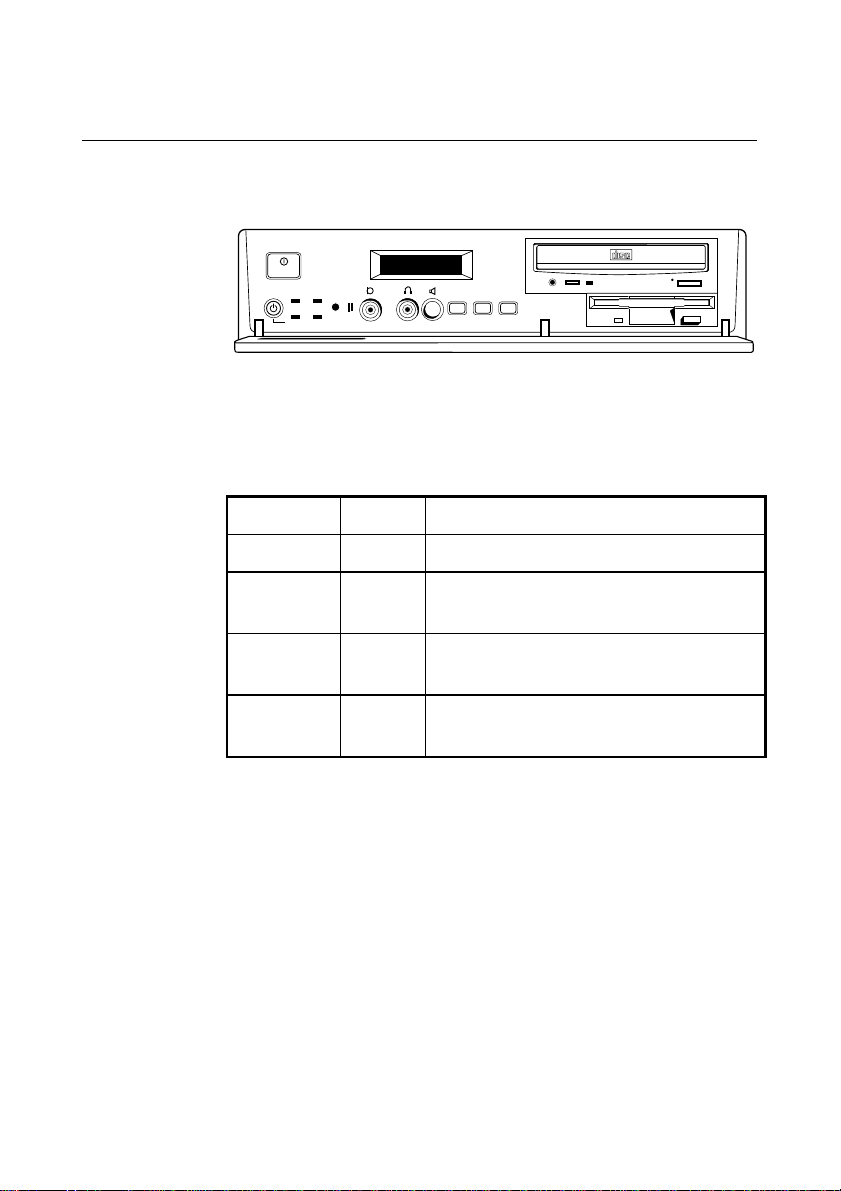
The computer comes with many front panel controls, and activity
indicators which are all relatively simple to use:
The
switch is used to turn the computer and monitor on and off.
POWER
The following table lists the colours of the various LED’s on the
front bezel and explains their meaning when active (i.e. when the
LED displays the colour indicated below):
Indicator LED Meaning when active
Power On Green The system is powered.
Standby Yellow The monitor has entered standby mode. The
Message Red There is an unread message in the Message
Hard Disk
Drive
The Control Function Display
The LCD Control Function Display is a display panel which informs
you of any unexpected situations such as power loss, loss in signal
etc. When the computer is switched on, the LCD displays the
horizontal and vertical refresh rates of the monitor.
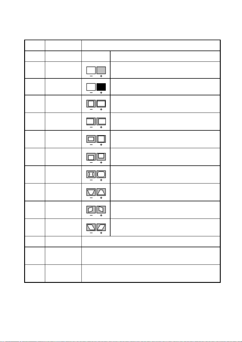
The LCD Control Function Display also has a menu which allows
you to alter the following monitor settings:
LED will begin to flash.
Centre.
Green The computer is using the hard disk drive.
2/2 MS 530 OWNER’S HANDBOOK
Page 16
Using your Computer
Menu Option Function
HYP Hypersound ON/OFF Enable/Disable wider sound spectrum.
CNT Contrast
Alters the contrast level of the monitor.
BRT Brightness
Alters the black level of the screen.
HSC H-Size
HPC H-Position
VSC V-Size
VPC V-Position
PCC Pincushion
TRA Trapezoid
RRC Raster
Rotation
PRL Parallelogram
Alters the horizontal size of the image on the
screen.
Alters the horizontal position of the image on
the screen.
Alters the vertical size of the image on the
screen.
Alters the vertical position of the image on the
screen.
Straightens the left and right sides of the
screen image.
Adjusts the parallelism of the left and right
sides of the screen image.
Adjusts the rotation or twist of the picture.
Adjusts the vertical slant or tilt of the screen
image.
CTC Colour Temp Adjusts the level of blue and red colour in the screen image.
DEG Degauss This is used to eliminate possible colour shading or
impurity.
CNV H-Static-Conv Adjusts the horizontal alignment of the red, green and blue
beams.
MS 530 OWNER’S HANDBOOK 2/3
Page 17
Using your Computer
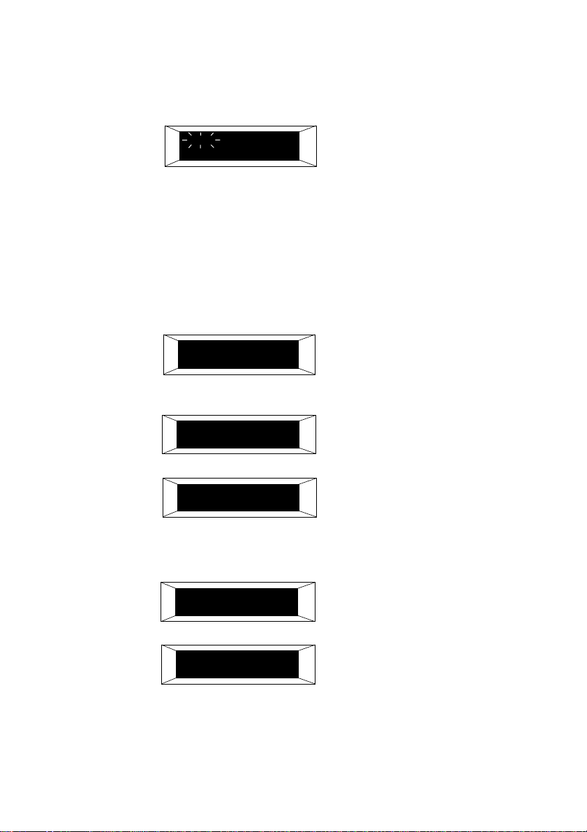
To alter any of the above features, the
button needs to be
MENU
pressed to display the menu:
HYP CNT BRT
The + and - buttons (next to the
button) can be used to
MENU
toggle between the various options in the menu. As you step
through the various options they begin to flash. To select the option,
press the
button when the required option is flashing.
MENU
You will then be able to alter the current level of the selected option
by pressing either the + or - buttons, to increase or decrease the
current level. The change is indicated by a series of asterisks below
the selected option:
BRIGHTNESS
*********************
The warning messages you are most likely to come across are:
STAND BY
The monitor has entered standby
mode. The standby LED will flash.
NO SIGNAL !
The system may have entered into
power down mode.
These two warning messages are normal during the operation of the
system if the motherboard has entered standby mode.
EMERGENCY !!!
ALL POWER DOWN !
BEAMLIMIT !!!
ALL POWER DOWN
2/4 MS 530 OWNER’S HANDBOOK
There is a fault condition, turn the
system off.
There is a problem, turn the system off.
Page 18
If you ever come across any of the above warning messages, then it
5-4
+
+
is advisable to turn the computer off, check that the power cord is
securely and correctly in place, and then switch the power back on.
If the problem persists then contact your local authorised dealer.
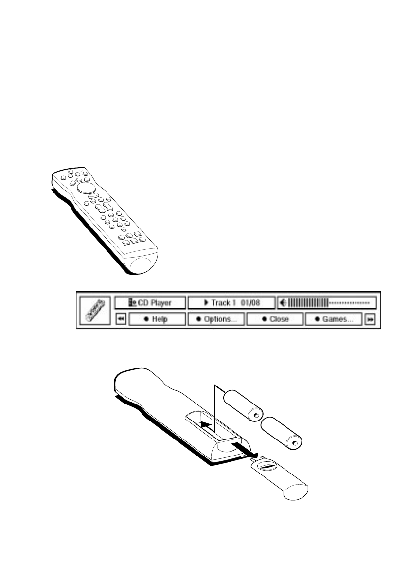
Using the Infra-Red Remote Control
The infra-red remote control offers a friendly user interface that is
immediately familiar to the inexperienced user.
It has an integral two-button mouse to control the
major functions of the multimedia applications.
Pressing the HELP button on the remote control
displays the ‘Remote Status’ window (shown below).
Pressing the red coloured button, labelled Help on
the ‘Remote Status’ window displays the on-line
help file. An on-line tutorial is also included in the
help file.
Using your Computer
The infra-red remote operates on two standard AA batteries which
are inserted into the remote as shown below:
MS 530 OWNER’S HANDBOOK 2/5
Page 19

Using the System Drives
3 USING THE SYSTEM DRIVES
This chapter details useful information on the correct operation of
the drives fitted to your computer.
MS 530 OWNER’S HANDBOOK 3/1
Page 20
Using the System Drives
Using the 3.5" diskette drive
The floppy disk drive is usually configured in the system BIOS as
drive A:, with a capacity of 1.44 Mbytes.
The 3.5" diskette drive fitted to your computer can read and write
both 720 Kbytes disks (if marked “DD” or “double density”) and
1.44 Mbytes disks (if marked “HD” or “high density”). The HD
disks can hold twice the capacity of DD disks, it is therefore more
economical to purchase them.
Each diskette has a rigid plastic cover with a metal shutter that
guards the disk surface. The drive automatically moves the shutter
aside to read the diskette.
Caution
Never touch the exposed surface under the shutter; you could deform the disk
or leave a fingerprint that might make it difficult to read.
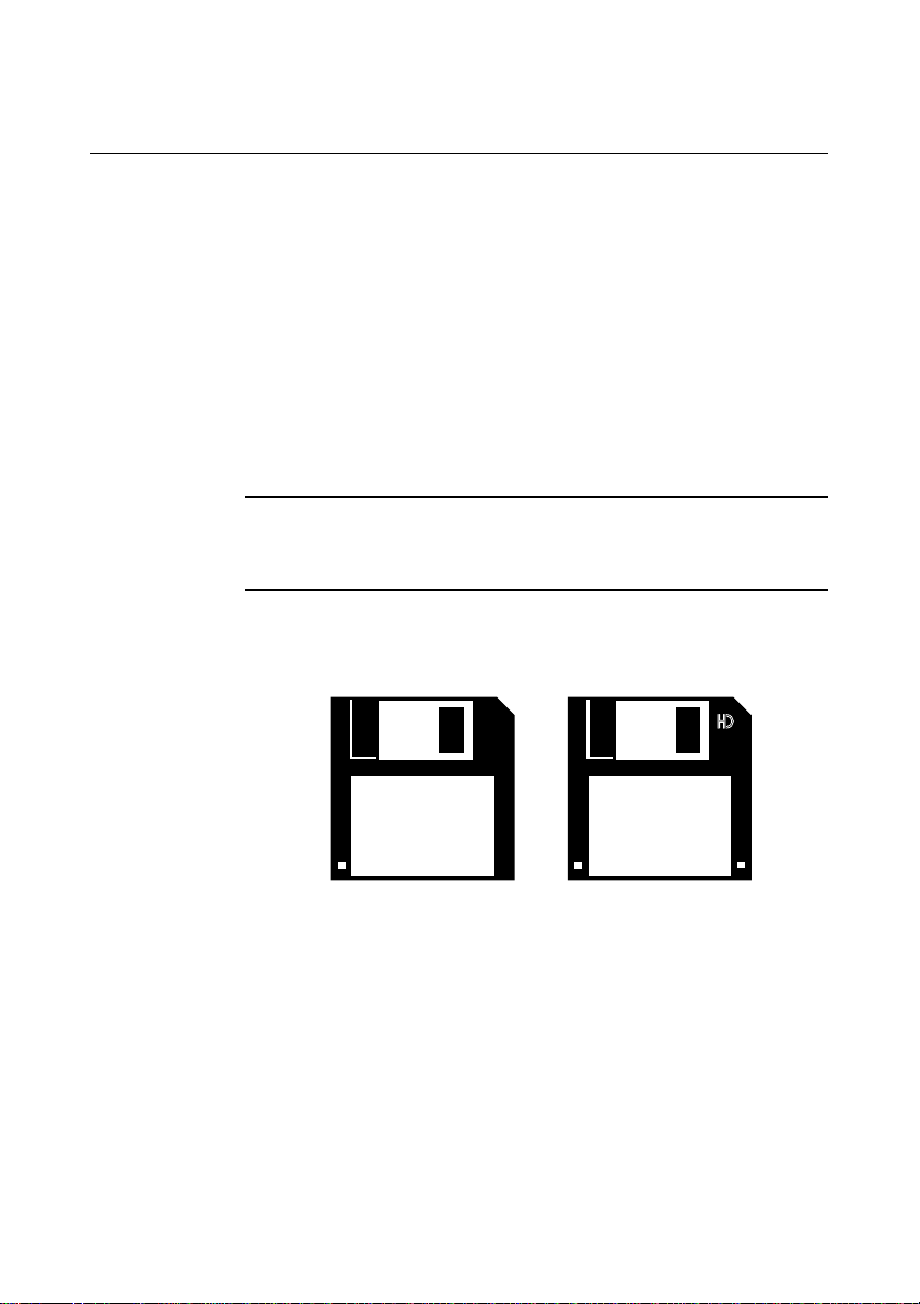
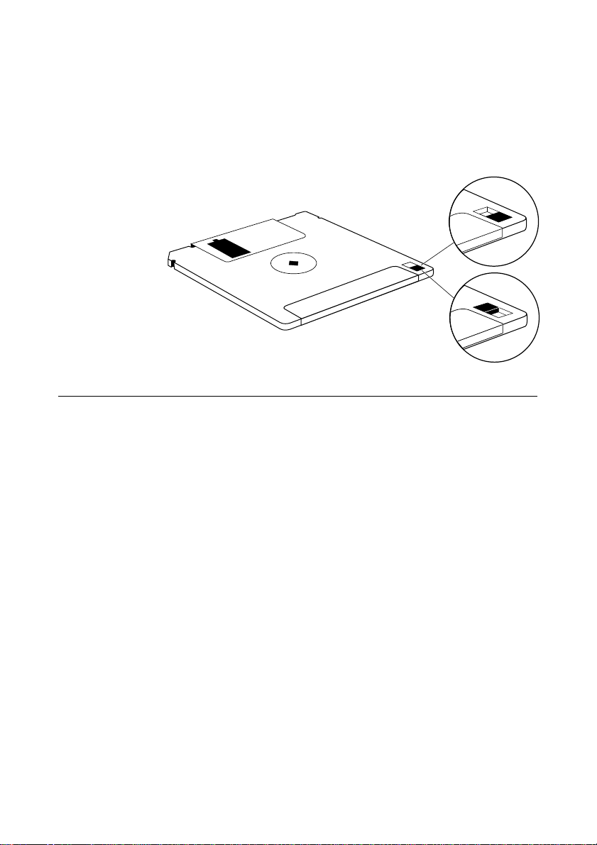
The immediate physical differences between the HD and DD floppy
disks are shown in the diagram below:
The HD disks have the ‘HD’ logo near the window and an extra
hole beside the label. This enables the drive to distinguish between
the two. The other hole which exists on both disks is the write
protect tab (on the underside). Keep diskettes well away from dust,
moisture, magnetic objects, and equipment that generates magnetic
fields. Also, avoid extremes of temperature and exposure to direct
sunlight. Otherwise, data recorded on the diskette may become
corrupted.
3/2 MS 530 OWNER’S HANDBOOK
Page 21
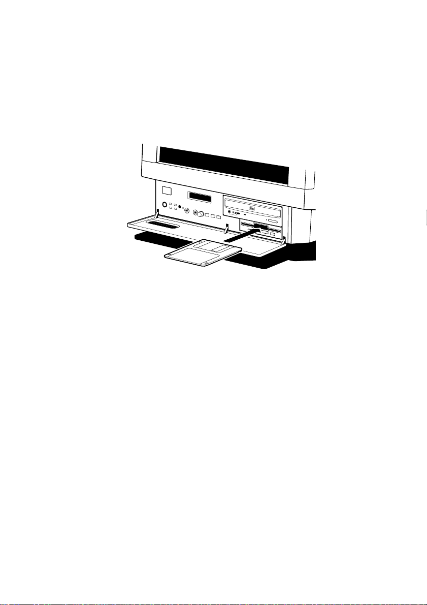
Inserting a diskette
COMPACT
A diskette is inserted into the diskette drive slot shutter-foremost,
and with its label side facing up. Some diskettes have a small arrow
on the face of the diskette; this must point towards the drive when
you insert the diskette:
Push the diskette all the way in until it engages with the drive
mechanism. When the drive’s eject
fully engaged.
Using the System Drives
button pops out, the diskette is
Removing a diskette
Before attempting to remove a diskette, make sure that the drive is
not currently in use (the diskette activity indicator, opposite the
drives eject
The drive mechanism disengages and the diskette is ejected half-way
out of the drive.
If a diskette becomes stuck in the drive, perhaps because its label has
peeled back, do not attempt to remove it with tweezers or any
similar implement; you risk damaging the drive. Call an authorised
maintainer.
Write-protecting a diskette
A diskette can be write-protected by sliding a small tab towards the
edge of the diskette to expose the little hole beneath it (see
button must be unlit). Press the eject button on the drive.
MS 530 OWNER’S HANDBOOK 3/3
Page 22
Using the System Drives
PROTECTED
UNPROTECTED
diagram). With the tab in this position, you can read, copy or print
files from the diskette, but you cannot create, rename or delete any
files. The BIOS Setup utility can disable the diskette drive, or make
it read-only. See Appendix B, “System BIOS and Setup”.
Using the CD-ROM Drive
The CD-ROM drive can retrieve multimedia data from CD-ROM
discs and multi-session Photo-CD discs. It can also play commercial
audio CDs.
The software required to control the CD-ROM drive depends on the
operating environment; see the Help provided with your computer
or ask your supplier for details.
It is important that the computer is not moved while a CD is in the
drive, especially if the CD is being played at the time.
The laser beam inside the CD-ROM drive is harmful to
the eyes. Do not attempt to disassemble the CD-ROM
drive. If a fault should occur it is advisable to contact an
authorised maintainer.
The CD-ROM LED should illuminate to green when the system is
powered. When it is active (i.e. busy reading information) it changes
to yellow.
3/4 MS 530 OWNER’S HANDBOOK
Page 23
Using the System Drives
COMPACT
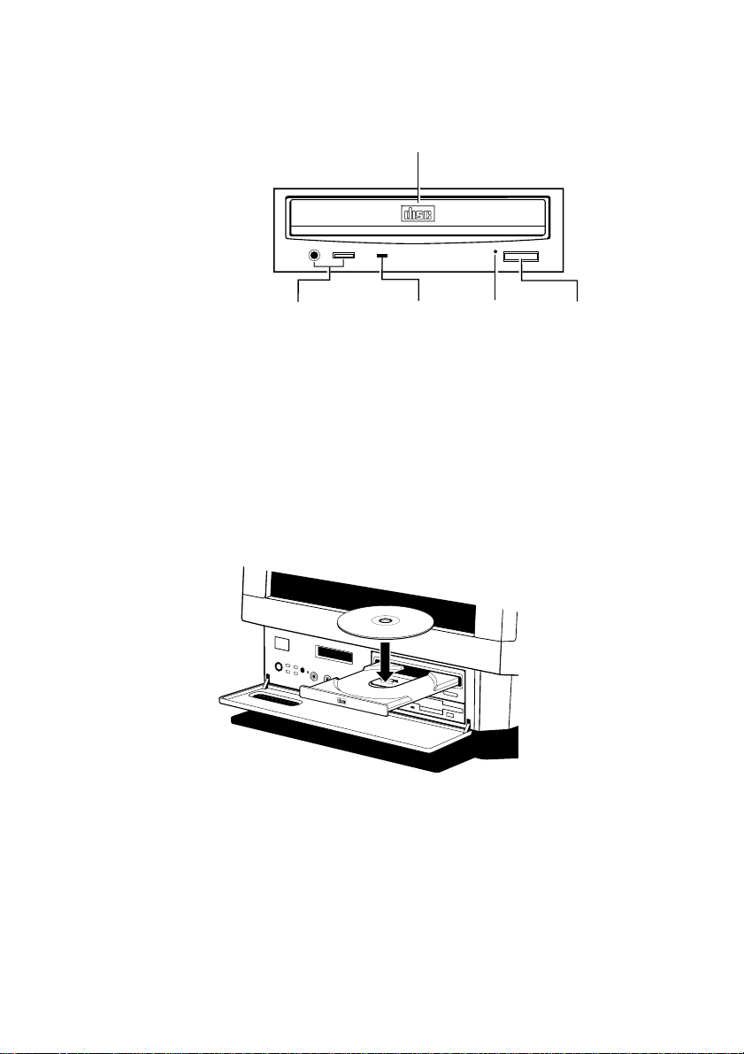
The CD-ROM drive has the following features:
DISC DRAWER
COMPACT
AND HEADPHONE LEVEL
The headphone socket and volume control can be used whilst
listening to commercial audio or music CDs (providing you are not
using external speakers, or feeding the output to your hi-fi). You can
still use all the other various features of your computer whilst you
are playing the audio CD.
Inserting a compact disc
Press the
on the platter:
Gently push the button again, or push the front of the platter to
draw it back into the drive.
HEADPHONE JACK
button on the front of the drive and place the CD face up
BUSY
INDICATOR
EMERGENCY
EJECT HOLE
EJECT
BUTTON
Removing a compact disc
Before attempting to remove a CD, ensure that the drive is not
currently active (the drive’s activity indicator should be green).
MS 530 OWNER’S HANDBOOK 3/5
Page 24
Using the System Drives
COMPACT
Press the button. The drive mechanism disengages and the platter is
ejected.
Note
Some software programs can temporarily override the eject button. They do
this to prevent the user from inadvertently interrupting the CD operation.
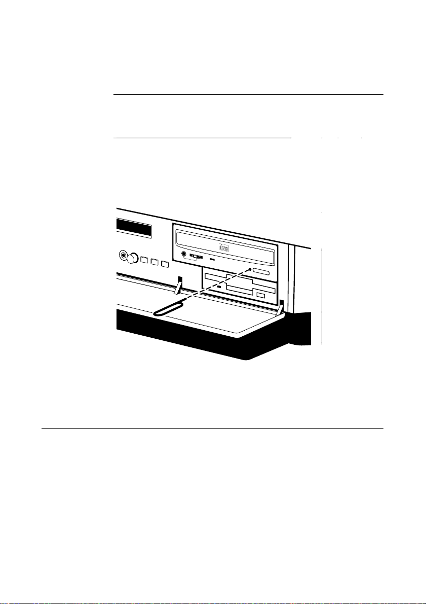
To eject the drawer manually (for example, during a power failure)
you must ensure that the computer is turned off. Then insert a thin
metal rod (such as a unwound paper clip) into the emergency eject
hole and push, see below:
Keep CDs well away from dust and moisture, and avoid touching
the surface of the CD. Also, avoid extremes of temperature and
exposure to direct sunlight.
Using the hard disk drive
Apricot computers are supplied with one internal or ‘primary’ hard
drive designated as drive C: in the system BIOS. The operating
system will normally be installed on this drive and it will only have
one partition which will have been made active as the bootable disk.
Data is stored on the hard drive in directories and subdirectories,
often referred to as ‘folders’, for example, most of the Windows 95
3/6 MS 530 OWNER’S HANDBOOK
Page 25

DriveSpace
Software Backup
Using the System Drives
programs and utilities can be found in the C:\WINDOWS
directory. More details can be found in the Windows 95 User’s
Guide and Help. Information on software tools, such as one to
compress the software into smaller space or, one to defragment your
files and make them easier to access can also be found here.
It is possible, as an alternative to the expense of fitting a hard drive,
to use the disk utility software such as DriveSpace within Windows
95, which appears to increase and often more than double the size
of the hard drive using software compression technology. Refer to
the Windows 95 Help files for further details on this utility. It is
advisable to backup your data before you do so.
Within Windows 95 there is considerable help on numerous topics
including backing up or, making security copies of your software. It
is vital to maintain discipline of regularly backing up your data.
Power cuts or hard disk failure being just two reasons to do so.
Your operating system and/or applications e.g. word processing
software can be easily re-installed from your master disks but the
letters, reports which you have created would be lost permanently.
Copy your data files to floppy disks or, use proprietary software
designed to do software backups, such as the one in Windows 95,
then keep them in a safe place. Your files may not be very large but
they will be impossible to replace once lost.
MS 530 OWNER’S HANDBOOK 3/7
Page 26

The Multimedia Applications
4 THE MULTIMEDIA APPLICATIONS
This chapter details instructions on how to access the software
which comes with your computer, further detailed information can
be found in the help files which come with the applications.
MS-530 OWNER’S HANDBOOK 4/1
Page 27
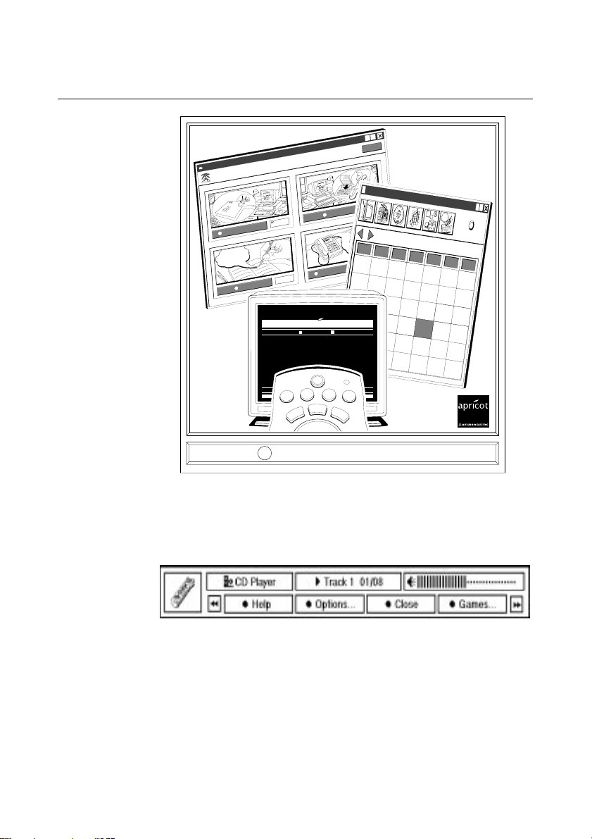
The Multimedia Applications
Apricot Message Centre
Message Centre - Contents
Message Centre - Contents
FAX
0
Voice Message
5
Electronic Mail
25
Memo
0
?
?
Help
Help
3
?
?
side1
T
h
e
V
e
r
y
b
e
s
t
o
f
9
0
s
I
n
d
i
e
M
u
s
i
c
Apricot Scheduler
AUGUST 1995
31123456
7 8 9 10111213
14 15 16 17 18 19 20
21 22 23 24 25 26 27
28 29 30 31 1 2 3
45678910
AUGUST 1995
?
Mon
Tue Wed
Thu Fri Sat Sun
PAGE 401 01 02 03 04 05 06 07 08 09 10 11 12 13 14+
APRICOT INSIGHT P401 AUG10 14:35:25
B I R M I N G H A MB I R M I N G H A M
Insight into apricot computers
Insight into apricot computers
INTRODUCTION...........................P402
THE MARKET...............................P403
THE APRICOT APPROACH..........P404THE APRICOT APPROACH..........P404
ARCHITECTURE...........................P405
APRICOT SERVERS.....................P406APRICOT SERVERS.....................P406
APRICOT DESKTOPS..................P407APRICOT DESKTOPS..................P407
APRICOT MULTIMEDIA................P408
INDUSTRY STANDARDS..............P409
RELIABILITY.................................P410
CONFIGURABILITY.......................P411
SECURITY.....................................P412
HARDWARE INTEGRATION......P413
CONNECTIVITY.........................P414
GRAPHICS.................................P415
DESIGN......................................P416
EXPANSION...............................P417
PERFORMANCE........................P418
SPECIFICATIONS......................P419
DEALERS..................................P420
COMPETITIVE PRICES.............P421
FINANCE...................................P422
LEASING...................................P423
APRICOT HELP P450
FINANCE
SOFTWAREHARDWAREPRODUCTS
A LOOK AT NEW PRODUCTS FOR 1996 P403
M
E
S
S
A
G
E
T
E
L
E
T
E
X
T
T
V
C
D
S
T
A
N
D
B
Y
Press the button on the Remote to continue...
The Infra-red Remote Control
The infra-red remote control which comes with your system
provides you with a user friendly interface.
When the
status window appears:
This window provides you with the current status of the remote
controlled program. The example given above, shows the status of
the CD-ROM.
The four labelled coloured buttons provide additional functionality
when the status window is visible, and are selected by pressing the
corresponding coloured buttons on the remote control.
4/2 MS-530 OWNER’S HANDBOOK
HELP
button on the remote control is pressed the remote
Page 28
The Multimedia Applications
PAGE 401 01 02 03 04 05 06 07 08 09 10 11 12 13 14+
APRICOT INSIGHT P401 AUG10 14:35:25
B I R M I N G H A MB I R M I N G H A M
Insight into apricot computers t computers
Insight into apricot computers t computers
INTRODUCTION...........................P402
THE MARKET...............................P403
THE APRICOT APPROACH..........P404THE APRICOT APPROACH..........P404
ARCHITECTURE...........................P405
APRICOT SERVERS.....................P406
APRICOT DESKTOPS..................P407
APRICOT MULTIMEDIA................P408
INDUSTRY STANDARDS..............P409
RELIABILITY.................................P410
CONFIGURABILITY.......................P411
SECURITY.....................................P412
HARDWARE INTEGRATION......P413
CONNECTIVITY.........................P414
GRAPHICS.................................P415
DESIGN......................................P416
EXPANSION...............................P417
PERFORMANCE........................P418
SPECIFICATIONS......................P419
DEALERS..................................P420
COMPETITIVE PRICES.............P421
FINANCE...................................P422
LEASING...................................P423
APRICOT HELP P450
FINANCE
SOFTWAREHARDWAREPRODUCTS
A LOOK AT NEW PRODUCTS FOR 1996 P403
PC
apricot
TV Channel?
TV Wizard
Cancel
Finish
Television
TV Wizard
Station found
BBC2
Please wait while e teletext page is found
Teletext
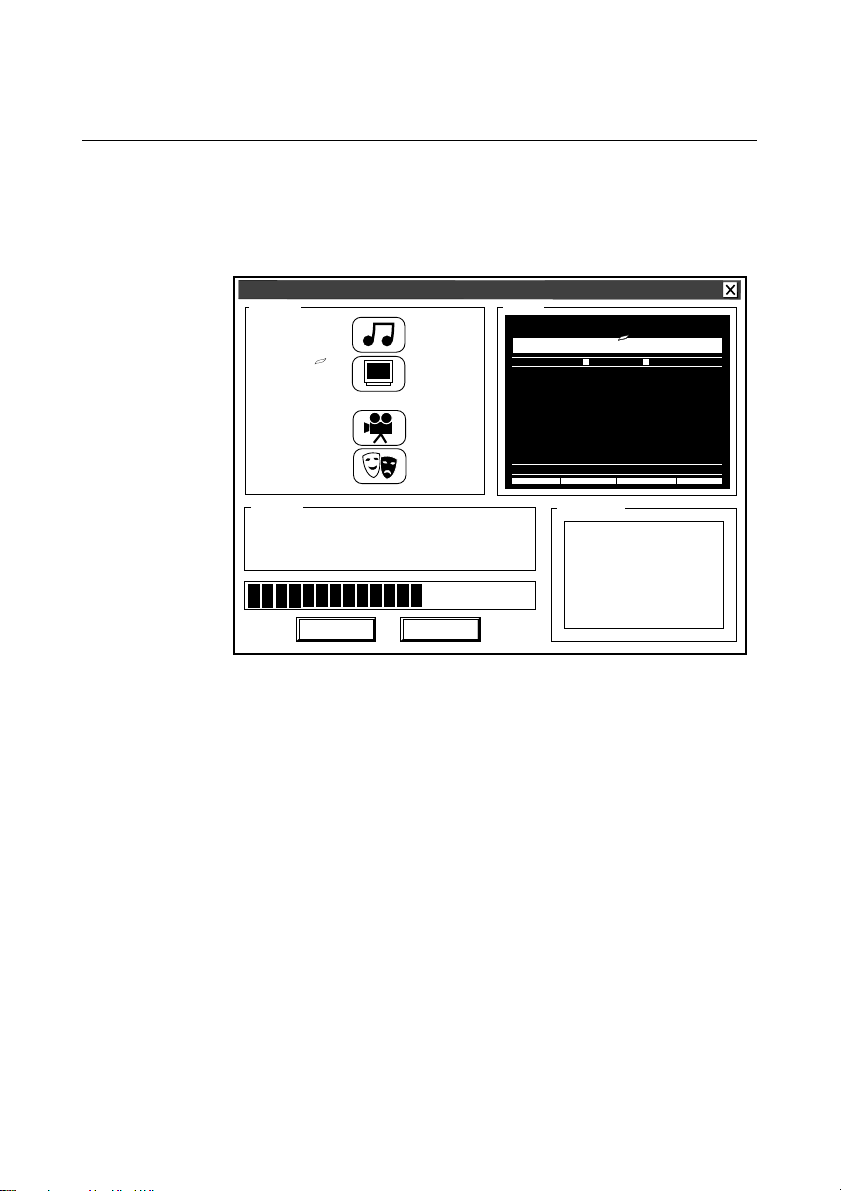
The Apricot TV/Teletext Application (Optional)
The Apricot TV/Teletext application provides full TV with integrated
Teletext support. You can access the TV application by pressing the
button on the remote control. Pressing this button for the first
TV
time activates the TV Wizard, shown below:
The TV Wizard will automatically tune into your local channels and
set the correct channel names, numbers and Teletext pages. Once
complete, the TV will start up in full screen mode.
Pressing the
TV
application between its various display modes: full screen, window,
and backdrop.
Right-clicking the mouse button anywhere on the TV application
causes a pop-up menu to appear allowing you to adjust various
settings.
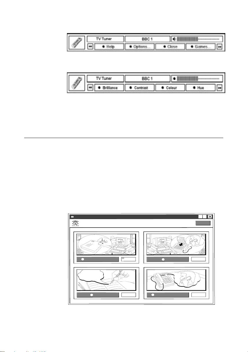
Some of the TV application settings can also be accessed by pressing
the
button on the remote control to display the remote status
HELP
window:
button on the remote control will toggle the TV
MS-530 OWNER’S HANDBOOK 4/3
Page 29
The Multimedia Applications
You then need to press the green button labelled ‘Options’ to list the
options you wish to alter:
Pressing any of the four coloured buttons selects the corresponding
option with its current level displayed as shown in the status
window above. You can increase or decrease the current level by
pressing either the ‘+’ or ‘-’ buttons on the remote control.
The Apricot Message Centre Application
The Apricot Message Centre application monitors your incoming
messages from the e-mail, fax or telephone systems.
The Message Centre LED on the front panel of the machine will
flash indicating that you have received a message in the Message
Centre. To find out what message has been sent, press the
MESSAGES
window with artistic views of the four message types that can be
accessed via the Message Centre:
button on the remote control. This will open a single
Apricot Message Centre
Message Centre - Contents
Message Centre - Contents
Electronic Mail
?
?
Memo
4/4 MS-530 OWNER’S HANDBOOK
Help
Help
0
0
FAX
Voice Message
10
5
Page 30
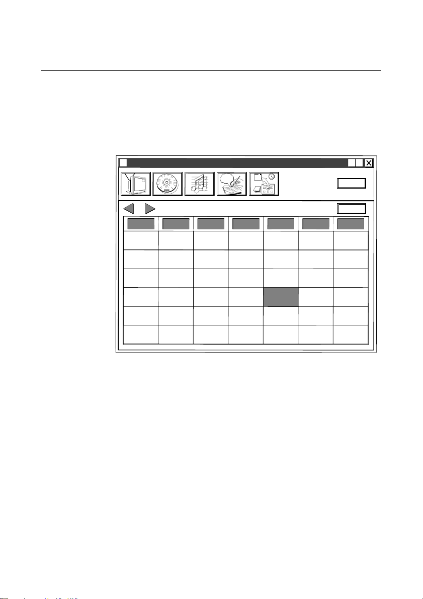
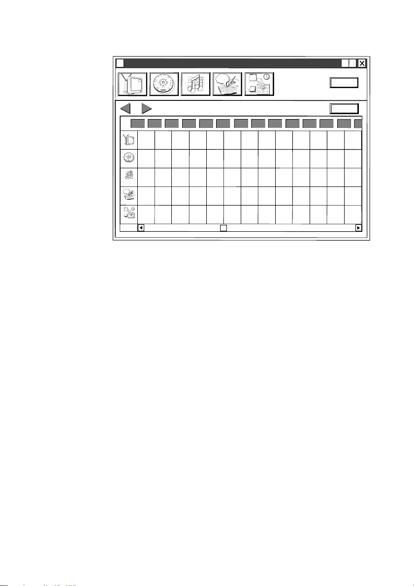
The Apricot Media Manager
The Apricot Media Manager application provides an easy way to
schedule the automatic launch of other software such as the TV, CD
applications. In addition the Media Manager allows you to create
automatic pop-up reminders and launch third-party applications.
Scheduling an event is easy with the user-friendly interface:
Apricot Management Centre
f
9
o
0
s
t
s
I
e
n
b
d
i
y
e
r
e
M
V
u
e
s
i
h
c
T
side1
The Multimedia Applications
?
?
3
Help
Day
Mon
AUGUST 1995
AUGUST 1995
Tue Wed
Thu Fri Sat Sun
31123456
7 8 9 10111213
14 15 16 17 18 19 20
21 22 23 24 25 26 27
28 29 30 31 1 2 3
45678910
The current day is highlighted by default with the number shown in
red.
Any other day is easily selected by clicking on the day with your
mouse, which subsequently becomes highlighted (as 25th August,
shown above). Then either, press the day button on the monthly
view, or double-click the selected day which takes you into the daily
view display:
MS-530 OWNER’S HANDBOOK 4/5
Page 31
The Multimedia Applications
Apricot Management Centre
f
9
o
0
s
t
s
I
e
n
b
d
i
y
e
r
e
M
V
u
e
s
i
h
c
T
side1
?
?
3
Help
18:00
Month
19:00
20:
e
b
y
r
e
V
Audio
?
?
Program
3
Reminder
Friday, 25 August 1995
Friday, 25 August 1995
7:00
8:00
9:00
10:00
11:00
TV
9
f
o
0
s
t
s
I
n
d
i
e
M
u
e
s
i
h
c
T
side1
CD
12:00
13:00
14:00
15:00
16:00
17:00
To schedule an event for any time of the day select the icon
corresponding to the event you wish to schedule.
For example, to schedule the launch of the TV application to coincide with
the beginning of the Nine o’clock News you would:
1. Select the TV icon from the top of the Daily View. This will then
display the TV dialog.
2. You will be prompted to enter the start and end times for the
event, this being 21:00 and 21:30 respectively.
3. The default display mode is set to full screen. If you wish to alter
the display mode then select the ‘Display’ tab to select your
display mode preference.
4. Select ‘BBC 1’ in the ‘Channels’ tab.
5. Select the ‘Repeat’ tab to schedule the event for the week.
6. Finally, assign a title such as, ‘The Nine o’clock News’ to the
event. This helps you identify the event before it is about to be
launched as the title will appear in the taskbar countdown.
Further detailed information can be found in the on-line help file.
4/6 MS-530 OWNER’S HANDBOOK
Page 32
The Multimedia Applications
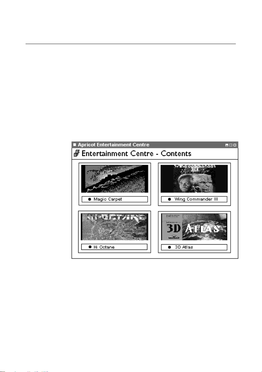
The Apricot Entertainment Centre Application
The Apricot Entertainment Centre provides you with an interface to
the games and multimedia programs which came with your system.
To access the Entertainment Centre press the
button on the
HELP
remote control, and then press the coloured button labelled ‘Games’.
Providing the games CD has been inserted into the CD-ROM drive,
pressing any one of the coloured buttons on the remote control will
load that particular game.
Before running your chosen game (except for the 3D Atlas program)
Windows 95 will shut down and reboot the system in DOS mode, there
is no reason to be concerned- this is meant to happen.
MS-530 OWNER’S HANDBOOK 4/7
Page 33
The Multimedia Applications
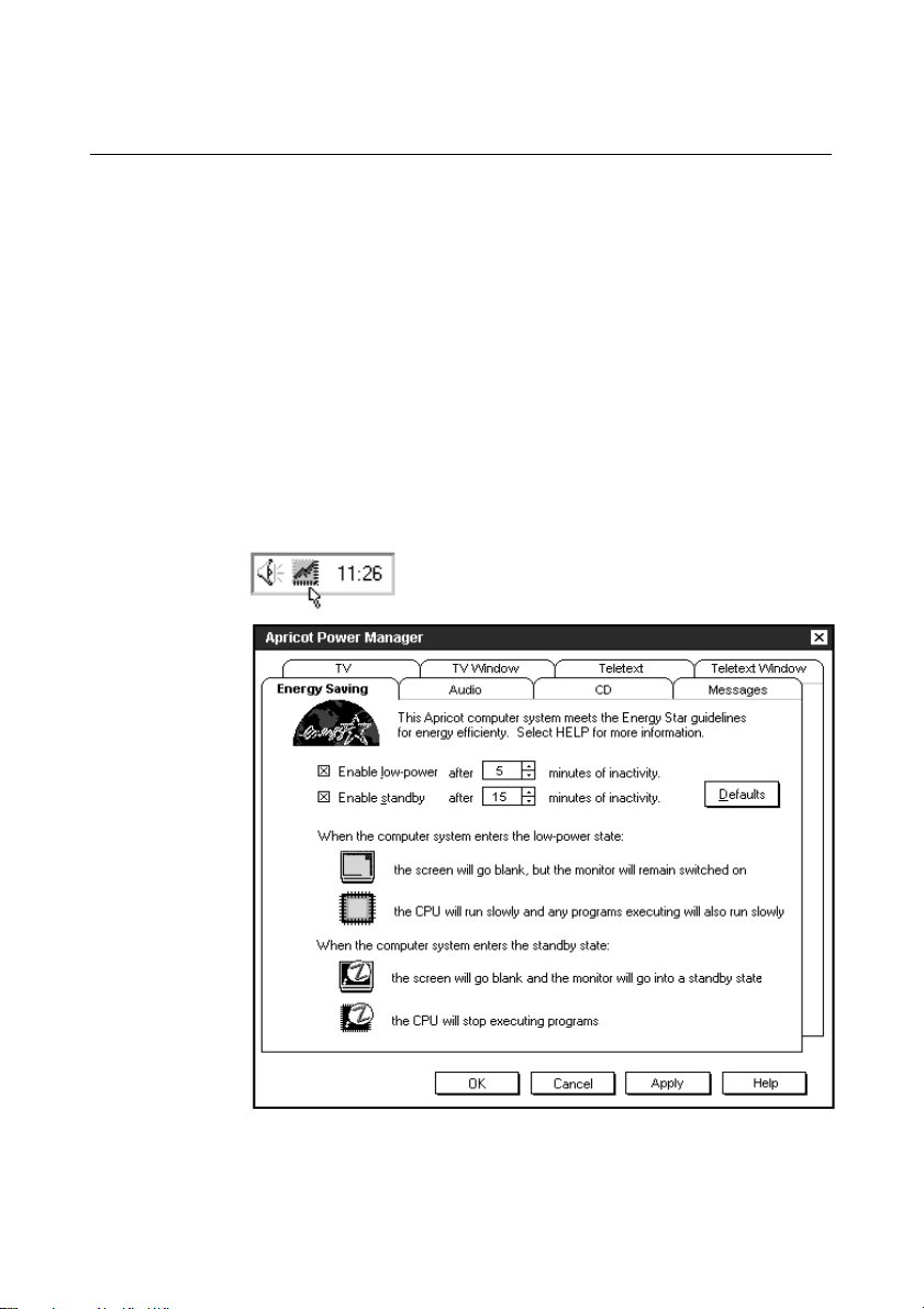
The Apricot Power Manager Application
Intelligent power management features come as standard with your
system. These features allow you to leave your system powered 24
hours a day much like your video recorder.
The system will power down into a ‘standby’ state if it has been left
idle for 15 minutes (default setting) or by pressing the purple standby
button on either the front panel of the system, or the remote control.
As you become more familiar with your system you may wish to
change some of the actions of your system. It is advisable that
inexperienced users do not attempt to alter any settings as you may
cause incorrect components to power down whilst using certain applications.
The Power Manager application is accessed by double-clicking the
following icon in the Windows 95 taskbar:
Refer to the on-line help file for further details.
4/8 MS-530 OWNER’S HANDBOOK
Page 34
The Radio Application (Optional)
The radio application is accessed via the remote control. Press the
button to display the remote status window, and then press the
HELP
coloured button on the remote control corresponding to the radio
application.
If you can not see the radio application listed, then you need to press:
the forward or rewind buttons on the remote control to step
through the options. You then need to press the coloured button
corresponding to the radio application on the remote control.
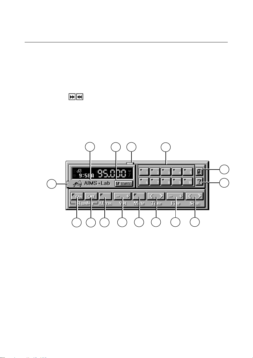
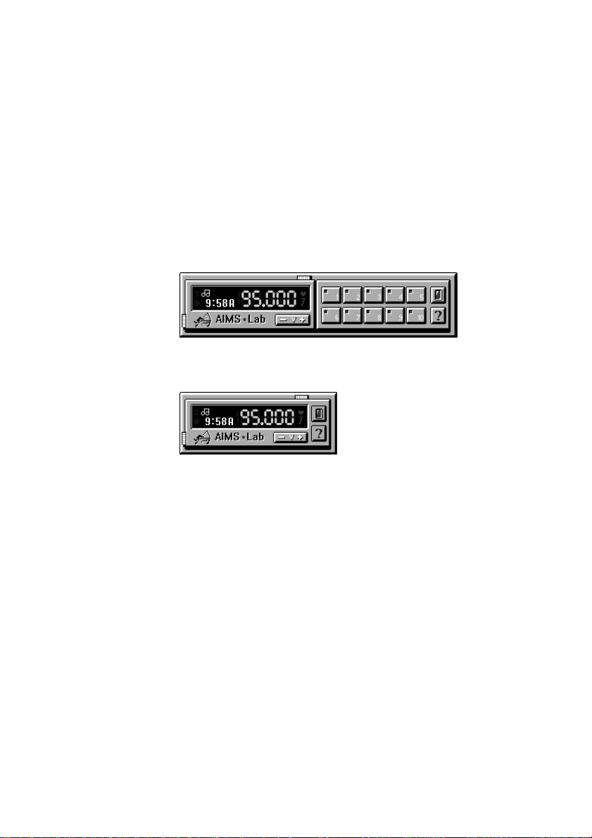
The radio interface is very easy to use, and is similar to a car radio
(shown below):
The Multimedia Applications
6
4
5
3
1
7
12
13
8
1 Power (On/Off)
2 Help button
3 Pre-set channel buttons (1-10)
4 Horizontal resize button
5 Memory button, saves the current frequency to a pre-set station.
6 Clicking the logo minimizes the radio display.
7 Vertical resize button
8 Radio mutes after pre-set time.
9 Turns the timer off.
10
9
11
14
15
2
MS-530 OWNER’S HANDBOOK 4/9
Page 35
The Multimedia Applications
10 Sets the radio to begin playing at the specified time.
11 Increase/decrease the volume.
12 Turns off the sound.
13 Increase/decrease tuner frequency (0.1 MHz).
14 Increase/decrease tuner frrequency (0.025 MHz)
15 Search next/previous stations.
Pressing the vertical resize button
makes the lower part of the display
➆
disappear:
Pressing the horizontal resize button ➃ makes the pre-set buttons disappear:
The Tune button is also used to set the hour setting on the alarm
and the minute setting on the slumber.
The Fine tune button is also used to set the minutes of the alarm.
Further detailed information can be found in the on-line Radio Help
file which is accessed by pressing the Help button
on the radio.
➁
4/10 MS-530 OWNER’S HANDBOOK
Page 36

System Upgrades
55 SSYYSSTTEEM M UUPPGGRRAADDEESS
Read this chapter before purchasing any upgrade. If in any doubt
consult your supplier. If, having read the relevant instructions, you
still do not feel confident about installing the upgrade, you may
wish to have your supplier or service organisation install it for you.
Before you start installing any upgrade you must be thoroughly
familiar with all the relevant instructions.
Appendix A, “Inside the System Unit”, provides: a guide to recommended antistatic precautions, instructions on how to pull out the LPX system
cage and information on motherboard jumpers.
The only tool required to complete the installation of the upgrades
is a small cross-head screwdriver.
Warning
Never carry out any work inside the computer with AC power applied. Turn
off the computer and unplug all power cords before starting work.
MS 530 OWNER’S HANDBOOK 5/1
Page 37

System Upgrades
Adding more system memory
The computer’s motherboard is fitted with sockets for four SIMMs
(single in-line memory modules) BUT two of them are obstructed by
the CD-ROM drive and therefore cannot be used.
The SIMMs sockets are located at the front of the mother-board.
SIMMs with capacities of 4, 8, 16 or 32 Mbytes are supported,
giving a maximum capacity of 64 Mbytes.
SIMMs must be fitted in pairs and the pair must be identical. The
system does not require parity checking (36 bit) SIMMs.
Conventional 32 Bit SIMMs with a refresh rate of 70ns for a 5V
power supply is the specification. The newer Enhanced Data Output
(EDO) type SIMMs are supported and will give enhanced
performance, more noticeably if L2 cache is not fitted.
This table shows all the supported memory configurations.
Total memory Bank0 Bank1
8 Mb 4 Mb 4 Mb
16 Mb 8 Mb 8 Mb
32 Mb 16 Mb 16 Mb
64 Mb 32 Mb 32 Mb
Installing and removing SIMMs
1. Turn off the computer and unplug the power cord.
2. Take suitable anti-static precautions and pull out the rear LPX
system cage.
Caution
If you are unfamiliar with the recommended anti-static precautions and/or
the process of pulling out the LPX system cage, refer to Appendix A, “Inside the
System Unit”.
3. Compare the current configuration of SIMMs with the
configuration for the memory upgrade you intend to install. You
MS 530 OWNER’S HANDBOOK5/2
Page 38
To install a SIMM
System Upgrades
will have to remove the existing SIMMs, before going on to
install the new SIMMs.
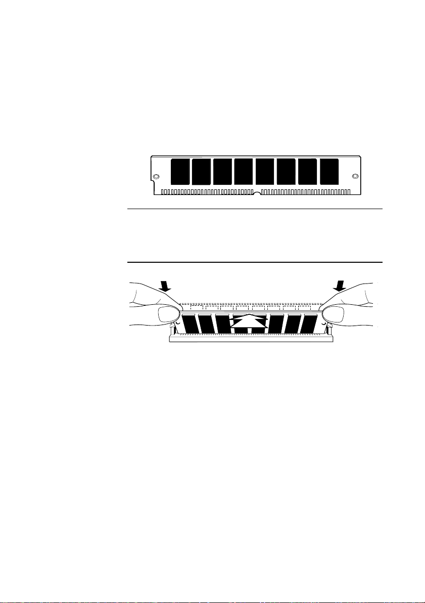
1. Take the SIMM out of its anti-static packaging. Hold it by its
edges and avoid touching the metal contacts.
Note:
The SIMM is not symmetrical. There are small notches in one end and
also slightly off centre along the connection edge, as shown below. it will
only fit into the socket one way.
2. Place the SIMM in the socket at a 15o angle to the vertical.
3. Pushing gently on its top corners, stand the SIMM upright in
the socket until the pegs of the socket engage the holes on the
SIMM and the metal clips hold both ends of the SIMM firmly in
position. Do not use excessive force.
4. If the SIMM will not fit easily, remove it and start again.
5. Repeat these steps for each SIMM you want to install.
MS 530 OWNER’S HANDBOOK 5/3
Page 39

System Upgrades
To remove a SIMM
1. Gently disengage the metal holding clips on each side of the
socket using your thumbs, while placing your forefingers on the
top edge of the SIMM. Then tilt the SIMM forward to about 15
to the vertical.
2. Lift the SIMM out of its socket. Hold the SIMM by its edges and
avoid touching the metal contacts.
3. Place the SIMM in suitable anti-static packaging.
When you have finished refit and secure the LPX system cage.
Reconfiguring the system
The first time you turn on the computer after adding or removing
SIMMs the memory change will be automatically detected by the
system BIOS, but you will have to confirm to the BIOS that the
change it has detected is correct. See Appendix B, “System BIOS and
Setup”.
If an error message occurs check that you have:
o
1. Installed a configuration supported in the list above.
2. Correctly fitted the SIMMs in their slots.
3. The SIMMs are of the correct type
It may be necessary to refit the original memory SIMMs to check if
there is a problem with your new SIMMs. If in any doubt contact
your supplier.
Adding more cache memory
An external or secondary level (L2) cache is a small amount of dedicated
memory with significantly faster access times than the computer’s
system RAM. A controller ensures that it always contains a copy of
the most recently accessed areas of RAM, so that the processor is
able to read it quickly.
MS 530 OWNER’S HANDBOOK5/4
Page 40

In this system a maximum of 64 Mb of RAM is cached.
First-level (L1) cache is contained within the processor itself, and is
not accessible. It could be either 8 Kb or 16 Kb.
You can improve the performance of some software applications by
adding or upgrading the L2 cache memory.
To decide if an upgrade is possible:
• You will need to enter ‘Setup’ to find out how much cache
• Check with your supplier to find out what upgrade kits are
To fit cache memory
1. Turn off the computer and unplug the power cord.
2. Take suitable anti-static precautions and pull out the LPX system
System Upgrades
memory the computer already has.
available.
cage.
Caution
If you are unfamiliar with the recommended anti-static precautions and/or
the process of pulling out the LPX system cage, refer to Appendix A,
“Inside the System Unit”.
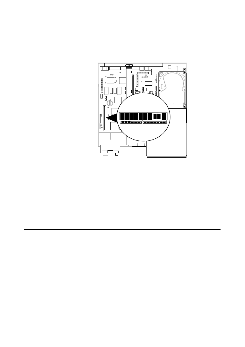
3. Identify the cache memory socket see Appendix A, “Inside the
System Unit”.
4. To fit or remove a module in the cache socket, you may have to
remove any expansion cards that are in the way. (Take note of
which way all the cables are connected). Disconnect any cables
connected to the cards, remove the screws that secure the cards
at the rear of the system unit, then remove the cards from the
system unit.
5. Remove the existing cache memory SIMM module (if fitted) by
carefully lifting by the edges. It is a tight fit.
MS 530 OWNER’S HANDBOOK 5/5
Page 41
System Upgrades
6. Fit the new cache memory SIMM module by aligning the module
with the slot and carefully pressing home. It will only fit in one
way; remember it is a fairly tight fit.
7. If necessary, replace any expansion cards you removed earlier
and reconnect all cables, etc.
8. Refit and secure the LPX system cage, reconnect the system and
switch on.
9. To check whether the new value of cache memory has been
registered by the system you need to enter ‘Setup’.
Adding more video memory
Video memory is memory reserved for use by the on-board EVGA
controller. More video memory provides more colours and/or
higher resolutions.
If your computer has only 1 Mbyte of video memory, you can
upgrade it to 2 Mbytes on board.
There are no changes to be made to the system BIOS. The only
immediate differences will be apparent when you come to make
changes to your video driver settings.
MS 530 OWNER’S HANDBOOK5/6
Page 42

System Upgrades
To add video memory
1. Turn off the computer and unplug the power cord.
2. Take suitable anti-static precautions and remove the system unit
cover.
Caution
If you are unfamiliar with the recommended anti-static precautions and/or
the process of removing the LPX system cage, refer to Appendix A, “Inside
the System Unit”.
3. If there are any expansion cards in the way, you may have to
remove them. (Take note of which way all of the cables are
connected.) Disconnect any cables connected to the cards,
remove the screws that secure the cards at the rear of the system
unit, then remove the cards from the system unit.
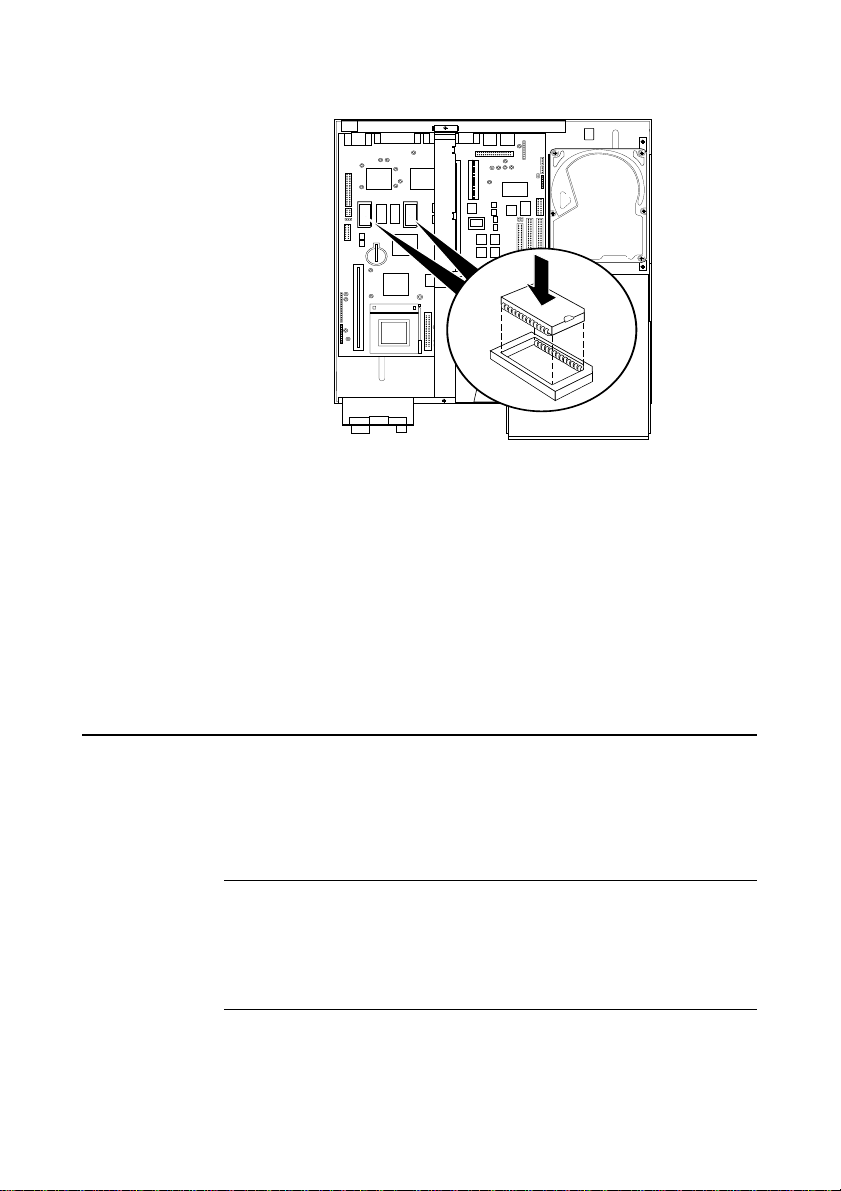
4. Identify the two video memory upgrade sockets, see Appendix
A, “Inside the System Unit”.
5. Unpack the upgrade kit and lay the memory chips out on an
anti-static surface. Hold each chip by its edges and be careful
not to touch the metal pins. These memory chips are particularly
static sensitive. Handle with extreme caution.
6. It is vital that the chips are fitted the right way round.
Each chip has a notch at one end or small bevel at one corner,
corresponding to the notch or bevel on the socket corner. These
must be aligned as shown.
MS 530 OWNER’S HANDBOOK 5/7
Page 43
System Upgrades
7. One at a time, press the chips in the sockets, push firmly home.
8. If necessary, replace any expansion cards you removed earlier
and reconnect any cables, etc.
9. Refit and secure the system unit cover. Then switch on and
check your system.
Remember, no immediate on-screen changes will be apparent,
unless there is a fault with the upgrade chips just fitted. Running the
video driver set-up software will highlight extra capabilities.
Upgrading the hard disk drive
The computer’s 3.5” hard disk drive bay can accommodate one 1”
high hard disk drive. If you feel that you need a high capacity hard
disk drive then you will need to purchase one and replace it with
the one currently fitted in your system.
Note
You will need to re-install all the software onto the hard disk. Any programs
or documents which you have created will need to be saved on floppy disks and
then saved on the ‘upgrade’ hard disk if you require access to them from the
hard drive.
MS 530 OWNER’S HANDBOOK5/8
Page 44
Installing the drive
COMPACT
To install the hard disk drive :
1. Turn off the computer and unplug the power cord.
2. If there is a diskette in the diskette drive, remove it.
3. Take suitable anti-static precautions and pull out the LPX system
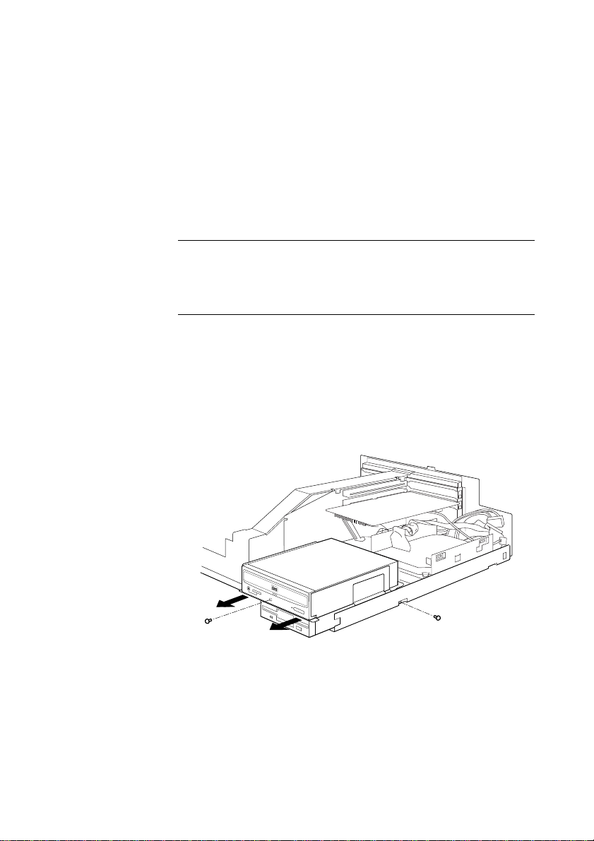
4. Unplug the power and signal cables from the rear of the CD-
5. Remove the two side screws which secure the CD-ROM and
System Upgrades
cage.
Caution
If you are unfamiliar with the recommended anti-static precautions and/or
the process of removing the LPX system cage, refer to Appendix A, “Inside
the System Unit”.
ROM and floppy drives.
floppy drives in place, (as shown below) and put them safely
aside. Slide the tray forward and lift it out of the system cage.
Put it down on a flat anti-static surface.
6. Unplug the power and signal cables of the current hard disk
from the rear of the drive.
MS 530 OWNER’S HANDBOOK 5/9
Page 45
System Upgrades
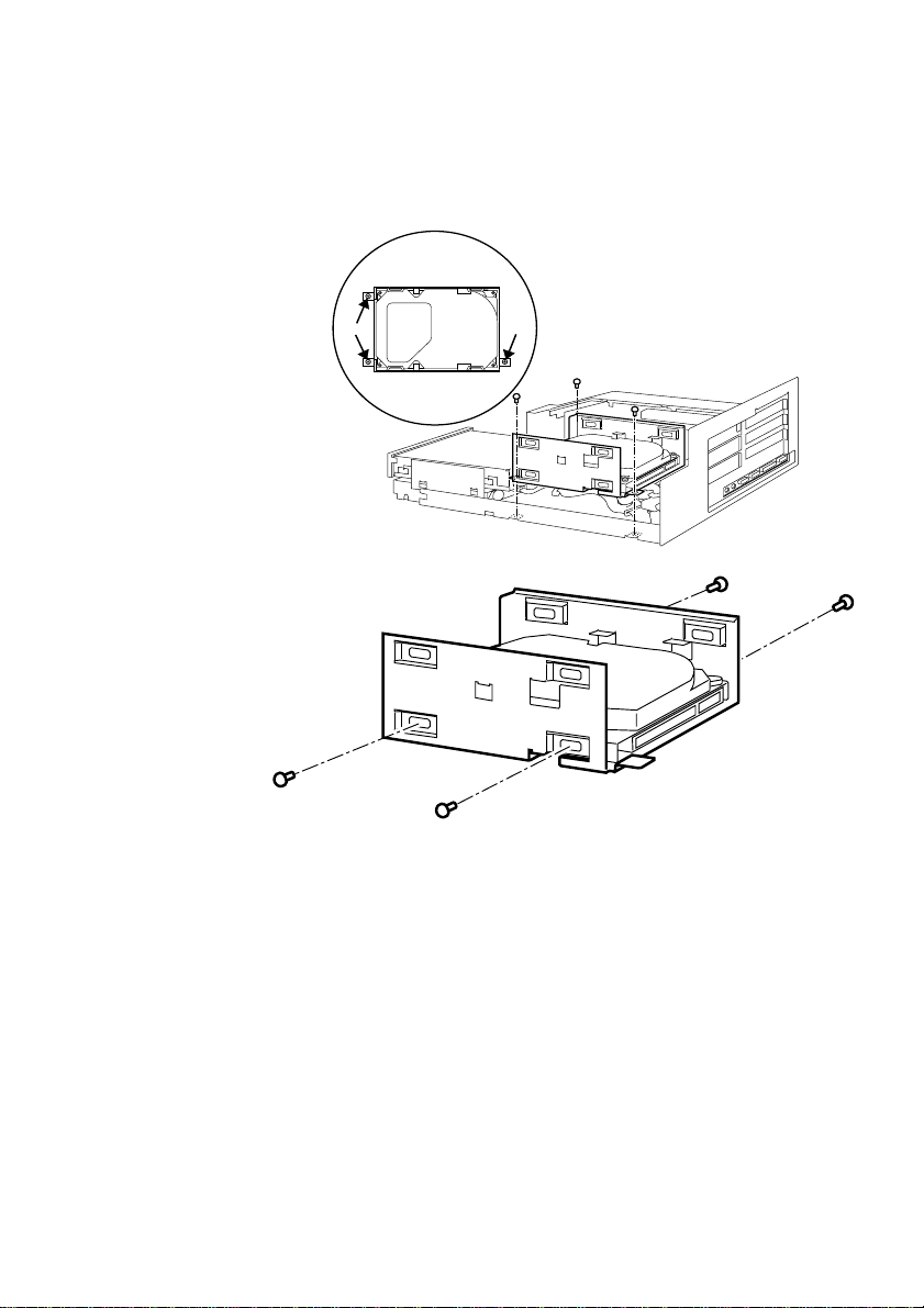
7. The hard disk drive bay is secured by three screws. Identify
these using the illustration shown below. Unscrew these screws
to remove the drive bay with hard drive from the system unit.
8. Unscrew the four screws which secure the hard disk drive into
the bay, as shown above.
9. Slide out the hard disk drive from the drive bay and place it on
an anti-static surface.
10. Place the upgrade hard disk into the drive bay and secure it with
the four screws.
11. Place the hard disk drive and bay into the system unit and
secure the drive bay back into the system unit.
MS 530 OWNER’S HANDBOOK5/10
Page 46

System Upgrades
12. Connect the hard disk’s power and signal cables.
13. Re-fit the CD-ROM and floppy drives into the system cage and
reconnect the power and signal cables for both.
14. Refit the LPX system cage.
Upgrading the processor
The computer is supplied with a Pentium processor. The ZIF (zero
insertion force) processor socket on the motherboard is designed to
accept a variety of Intel processors.
You can upgrade your processor by replacing it with one of higher
performance. The motherboard supports the full range of OverDrive
processors known at the time of writing.
The system also supports a range of external clock speeds of 50, 60
and 66 megahertz (MHz). The clock speed is set by adjusting some
jumpers on the motherboard. Note that the external clock speed is
lower than the processor’s internal clock speed, which is usually the
one advertised. The ratio of the internal and external clock speeds is
known as the ‘processor clock multiple’.
Intel Pentium OverDrive
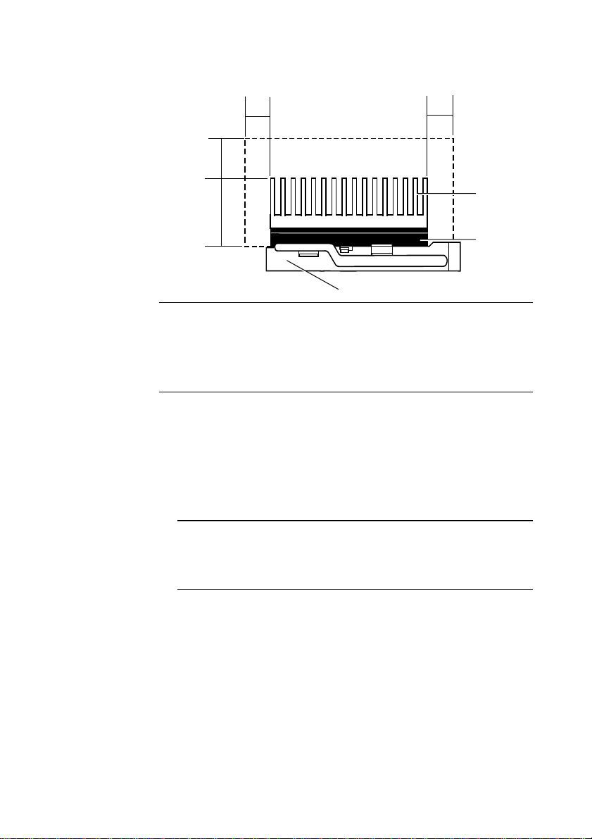
When installing an Intel Pentium processor, you must ensure that
there is sufficient air space around it. If you do not leave enough air
space, the processor may overheat. So, ensure that no obstructions
such as cables or expansion cards, intrude upon the open air space
shown below:
MS 530 OWNER’S HANDBOOK 5/11
Page 47
System Upgrades
0.2"/0.5cm
0.4"/1.1cm
1.0"/2.54cm
SOCKET
PROCESSOR
0.2"/0.5cm
HEATSINK
Warning
If you install a high power Pentium Overdrive and you have five expansion
cards fitted then you will probably have to remove some of the expansion
cards. This is due to high power consumption of the cards and OverDrive
processor which may cause problems that the system cannot cope with.
Removing and fitting a processor
MS 530 OWNER’S HANDBOOK5/12
To remove the existing processor:
1. Turn off the computer and unplug all power cables.
2. Take suitable anti-static precautions and pull out the LPX system cage.
Warning
If you are unfamiliar with the recommended anti-static precautions or the
procedure for pulling out the LPX system cage, refer to Appendix A,
“Inside the System Unit”.
3. If the computer was turned on prior to commencing this
procedure, wait at least 15 minutes for the processor to cool down
before proceeding.
Page 48
System Upgrades
1
2
Warning
The processor can get very hot. You may burn your fingers if you attempt
to remove the processor before it has cooled down. Also, the processor’s
pins expand slightly when hot and this can prevent it being removed from
the socket.
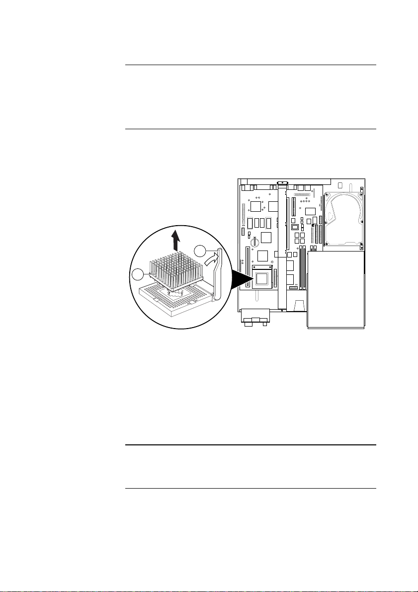
3. To locate the ZIF processor socket, refer to Appendix A, “Inside
the system unit”. The lever attached to the socket secures the
processor in the socket.
4. Lift this lever [1] from its locked position until it is upright (at
right-angles to the motherboard). The first and last 15° of
movement may require significant effort. Apply just enough
pressure to overcome the resistance offered by the lever.
5. Lift the processor [2] out of the socket and place it on an antistatic surface outside the system unit. Hold the processor by its
edges and avoid touching the metal pins.
Caution
If the processor does not lift easily out of the socket, do not attempt to force
it. Wait for the processor to cool down.
MS 530 OWNER’S HANDBOOK 5/13
Page 49
System Upgrades
To fit the upgrade processor:
1. Ensure that the securing lever on the ZIF socket is still in the
upright position.
2. Take the upgrade processor out of its anti-static packaging. Hold
the processor by its edges and avoid touching the metal pins.
The upgrade processor and the ZIF socket are keyed to ensure
that the processor is installed in the correct orientation. One
corner of the socket has a key hole (see below). The corresponding
corner of the processor is slightly bevelled and has a positioning
guide in the form of a coloured dot.
2
1
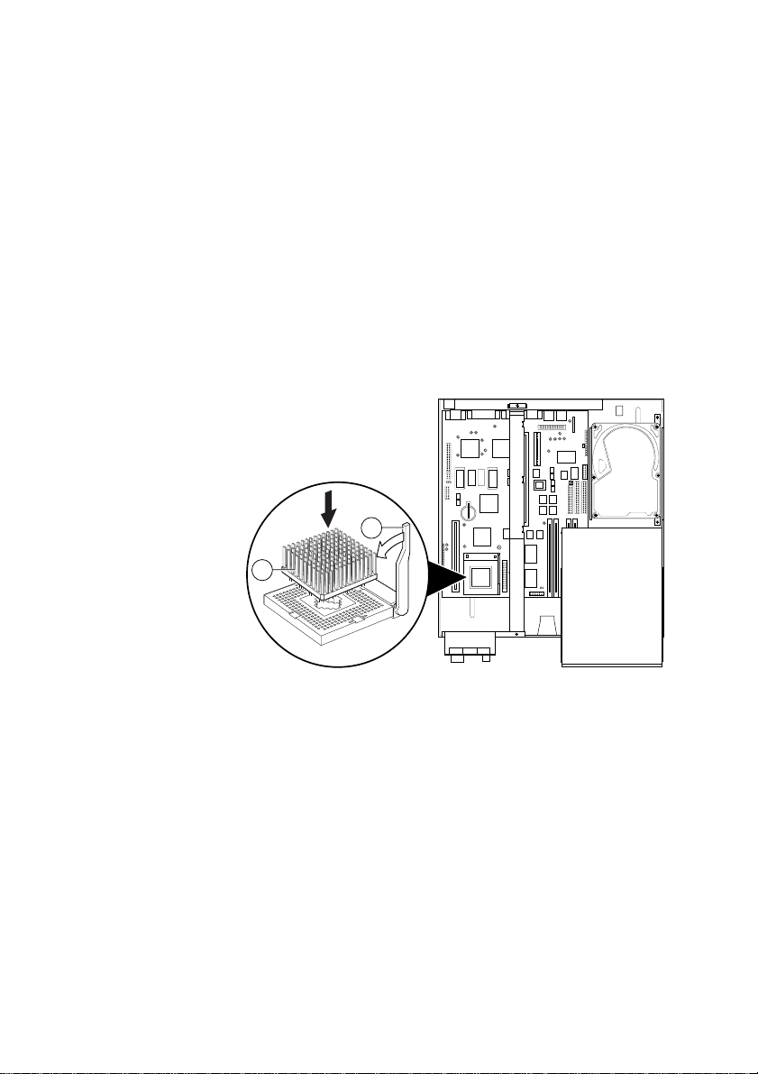
3. Place the processor in the socket [1], making sure that it is
correctly aligned and that you do not bend or otherwise damage
the pins.
If the upgrade processor is not big enough to occupy all four
rows of holes in the socket it should be positioned centrally (as
shown on the previous page).
MS 530 OWNER’S HANDBOOK5/14
Page 50

System Upgrades
Caution
If the processor is misaligned it will not go into the socket, and any attempt
to force it will damage the processor, or the socket, or both.
5. Move the securing lever in the locked position. Apply just
enough pressure to overcome the resistance offered by the lever.
6. You may need to adjust the Processor Selection and/ or External
Clock Speed jumpers on the motherboard.
See Appendix A, “Inside the System Unit”, for more information
about locating and adjusting motherboard jumper settings.
7. Refit the LPX system cage.
MS 530 OWNER’S HANDBOOK 5/15
Page 51

Expansion Cards
6 EXPANSION CARDS
This chapter contains instructions on installing expansion cards in
your computer. It is important that you read this chapter before
purchasing a card. If, having read the installation instructions, you
do not feel confident about installing the upgrade yourself you may
wish your supplier or service organisation to fit the card for you.
Before you start installing the card you should be thoroughly
familiar with the instructions. The only tool required is a small
cross-head screwdriver.
Appendix A, “Inside the System Unit” provides: a guide to recommended antistatic precautions, instructions on how to pull out the LPX cage and
disconnect the power and audio cables. Information on the
motherboard jumpers is also provided.
Warning
Never carry out any work on the equipment with power applied. Always
switch off at the mains and remove the power lead from the equipment before
starting work.
MS 530 OWNER’S HANDBOOK 6/1
Page 52
Expansion Cards
K
1/2 ISA
1/2 PCI
FULL ISA
1/2 ISA
1/2 PCI
AUDIO REAR CONNECTIONS
Your computer can accept various expansion cards or boards. Most
are simple to install with the benefit of the ‘Plug and Play’ features,
explained in the guide to Windows 95. (Look out for the ‘Plug and
Play’ symbol on the packaging of these add-in boards). You can
extend the capabilities of your computer, for example:
• A graphics/movie card can provide more specialised video
functions.
• A modem card can provide a connection to the Internet or a
bulletin board via telephone line.
• A television card can enable you to watch T.V. on your monitor
and capture individual frames.
• A radio card enables you to receive radio signals and tune into
your favourite radio station.
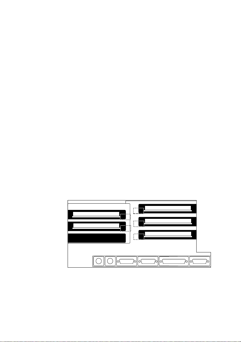
This computer system has room for:
One: full length Industry Standard Architecture (ISA) slot
Two: half length ISA slots
Two: half length Peripheral Component Interface (PCI) slot
These can be arranged into the internal RISER CARD generally as
shown in this rear view (the blanking plates have been removed for
simplicity of showing the layout).
6/2 MS 530 OWNER’S HANDBOO
Page 53

Expansion Cards
Configuring the card
Part of the installation procedure for many expansion cards involves
setting up or configuring the card so it works correctly in the
system. To configure, you assign values to various settings on the
card, which enable the card to communicate with the computer.
These must be registered in the BIOS see Appendix B, “System BIOS
and Setup” and the section ‘ISA Legacy resources’.
Many cards require that you specify at least two of the following:
• Interrupt request level (IRQ)
• Direct memory access (DMA) channel
• Base input/output (I/O) port address
• Base memory address
The important thing to understand is that the settings used by the
card must be different from the settings used by the other hardware
in the computer, whether another card or a component on the
motherboard, the settings must not conflict.
Some settings are done by jumpers and/or switches on the card and
are best done before installation, others are configured by running
installation software after installation. Some cards use a mixture of
both methods.
The documentation accompanying the card should tell you what is
required. Remember to check any diskettes supplied with the card
for README or other help files, before you start. If you are in any
doubt consult the supplier or manufacturer.
Cards often come with pre-configured or default settings. It is best
to rely on these settings as much as possible, and change them only
if they conflict with other devices.
MS 530 OWNER’S HANDBOOK 6/3
Page 54

Expansion Cards
K
ISA Interrupt request level (IRQ)
The interrupt request level or IRQ (the two terms are used
interchangeably) is the line over which the expansion card sends a
signal to get the attention of, or interrupt, the processor. Many of
these are reserved for components on the computer’s motherboard.
Some of these interrupts are fixed, others can be re-assigned, or
freed by disabling the component with BIOS Setup.
The following table lists the interrupts used by the computer and
shows which may be available for use by expansion cards.
IRQ Default assignment Available?
IRQ0 System timer No
IRQ1 Keyboard controller No
IRQ2 System No
IRQ3 Serial port 2 Optionally
IRQ4 Serial port 1 Optionally
IRQ5 Audio (if fitted) Yes
IRQ6 Diskette controller No
IRQ7 Parallel port Optionally
IRQ8 Real time clock No
IRQ9 Yes
IRQ10 Yes
IRQ11 Yes
IRQ12 Mouse No
IRQ13 Coprocessor No
IRQ14 Primary ATA/IDE interface No
IRQ15 Secondary ATA/IDE interface No
6/4 MS 530 OWNER’S HANDBOO
Page 55

Expansion Cards
IRQ3 is available if you disable serial port 2 with the BIOS Setup
utility.
Note:
If you disable IRQ3 then you will also disable the IR sensor used for the
infra-red remote control.
IRQ4 is available if you disable serial port 1.
Do not disable either one unless you have no intention of using the
affected port. Similarly, if you have no intention of using the parallel
port, you can disable it with the BIOS Setup utility, completely
freeing IRQ7 for use by an expansion card.
Direct memory access (DMA) channel
Some hardware devices can use a DMA channel to access system
memory without directly burdening the processor. Computers have
DMA channels numbered DMA0 to at least DMA7.
The following table lists the DMA channels used by the computer
and shows which are available for use by expansion cards. See the
notes below the table for further explanation.
DMA Default assignment Available?
DMA0 Yes
DMA1 8-bit Audio Optionally
DMA2 Diskette/floppy disk controller No
DMA3 Enhanced Capabilities Port (default) Optionally
DMA4 System No
DMA5 16-bit Audio Optionally
DMA6 Yes
DMA7 Yes
MS 530 OWNER’S HANDBOOK 6/5
Page 56

Expansion Cards
K
Base input/output (I/O) port address
I/O ports are used by the processor to communicate with hardware
devices. Some expansion cards are also controlled by I/O ports. The
base I/O port address specifies where the card’s ports begin. The
following table lists the I/O ports used by devices on the
motherboard. Any ports not listed below may be available for an
expansion card.
I/O ports Default assignment
000h-01Fh DMA controller 1
020h-021h Interrupt controller 1
022h-023h ALI configuration port
034h, 038h, 03Ch Alternate Local bus ATA/IDE
040h-05Fh System timer
060h-06Fh Keyboard controller
070h-07Fh Real-time clock, NMI mask
080h-09Fh DMA page register
0A0h-0A1h Interrupt controller 2
0B4h, 0B8h, 0BCh Local bus ATA/IDE
0C0h-0DFh DMA controller 2
0F0h, 0F1h Math coprocessor busy (clear/reset)
0F8h-0FFh Math coprocessor
1F0h-1F7h Hard disk drive controller
200h-207h Game I/O (disable)
220h-22Fh, 230h-233Fh Sound blaster system
240h-24Fh, 250h-253Fh Alternate Sound blaster system
278h-27Fh Parallel port 2
2B0h-2DFh Alternate VGA
2F8h-2FFh Serial port 2
300h-301Fh Alternate Midi (disable)
330h-331Fh Midi
6/6 MS 530 OWNER’S HANDBOO
Page 57

Expansion Cards
I/O ports Default assignment
378h-37Fh Parallel port 1
388h-38Fh FM synthesiser
3B0h-3BFh Monochrome display and printer adapter
3B4h, 3B5h, 3BAh Video subsystem
3C0h-3C5h VGA
3C6h-3C9h Video DAC
3CAh-3DFh VGA
3F0h-3F7h Diskette drive controller
3F8h-3FFh Serial port 1
Base memory address
Some expansion cards are fitted with memory of their own, usually
read-only memory (ROM) containing functional extensions to the
computer’s BIOS (basic input/output system) ROM. Some cards also
have random-access memory (RAM).
In order that this memory can be recognised by the system
processor, it must be mapped somewhere within the computer’s own
address space. By setting the base memory address you specify
where the card’s memory begins within the address space. Typically,
an expansion card’s memory must be mapped onto the addresses
between C8000h and EFFFFh in upper memory. With most modern
expansion cards this is fully automatic.
Note
Memory addresses are always written in base 16 (hexadecimal notation).
Hexadecimal uses sixteen digits (0-9 and A-F, where A=10, B=11 and so on up to
F=15). Hexadecimal numbers are denoted either by the suffix “h” or by the prefix
“0x”. The final digit of a five-digit memory address is often omitted, so C8000h may be
written as C800h. Since amounts of memory are usually stated as kilobytes rather than
in hexadecimal notation, the following conversion table may be helpful:
4 Kbytes = 1000h 8 Kbytes = 2000h 16 Kbytes = 4000h
32 Kbytes = 8000h 64 Kbytes = 10000h 128 Kbytes = 20000h
MS 530 OWNER’S HANDBOOK 6/7
Page 58

Expansion Cards
K
The card’s documentation should list its possible base memory
addresses. You will also need to know how much memory the card
has, so that you can leave the right gap between this card’s base
address and the next.
Installing the card
Installing expansion cards can be one of the most difficult
operations you may ever perform within your computer. If you are
in any doubt, or come into difficulties you are unable to resolve,
contact the supplier of the expansion card or ask your Apricot dealer
for advice or assistance.
1. Turn off the computer and unplug all power cords.
2. Take suitable anti-static precautions and remove the rear system
unit cover, detailed instructions are provided in Appendix A,
“Inside the System Unit”.
Note
If you are unfamiliar with the recommended anti-static precautions and/or
the process of pulling out the LPX system cage, refer to Appendix A,
“Inside the System Unit”.
3. At the rear of the system unit are metal blanking plates, one for
each expansion card slot. Opposite the blanking plates, at the
front of the system unit, there are card guides. These ensure that
the front edge of a full-length card is supported securely.
4. First decide in which of the available slots you wish to install the
card. In general it is easiest to start with the lowest slot and
work upwards.
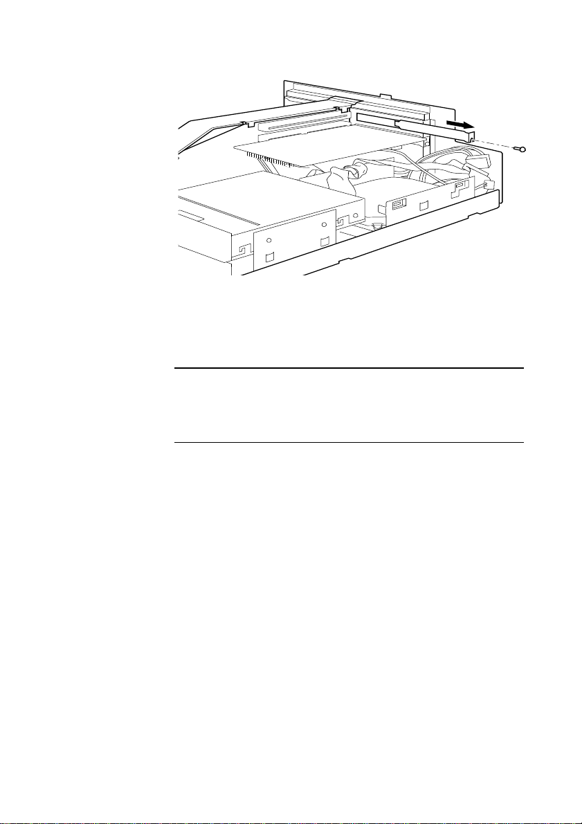
5. Remove the blanking plate of the chosen slot by removing its
securing screw, then sliding the blanking plate out of its slot.
Keep all the screws, etc., they will be needed later to secure the
card.
6/8 MS 530 OWNER’S HANDBOO
Page 59
Expansion Cards
6. If the card you are installing is configured by the means of
jumpers or switches, check that it is correctly configured before
proceeding.
Note
If the card uses the video feature connector on the motherboard, you may
need to connect this before you install the card (otherwise, the card could
get in the way of the connector).
8. Position the expansion card alongside the slot in which you
wish to install it. Align the rear of the card with the slot in the
rear of the system unit, and, if the card is full length, align the
front of the card with the card guide, into the bottom slot.
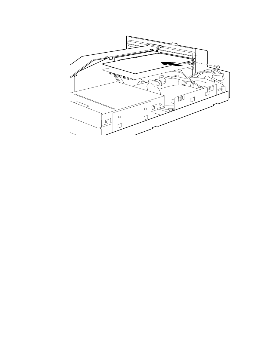
9. Slide the card into the slot ensuring that the card edge connector
engages correctly with the socket on the riser board. Do not use
excessive force.
MS 530 OWNER’S HANDBOOK 6/9
Page 60
Expansion Cards
K
10. Secure the card by replacing all the screws/clamps that you
removed in Step 5.
11. Connect any necessary signal cables to the card.
12. Check to ensure no other cables or connectors have become
dislodged and replace the system unit cover.
13. Read the manuals supplied with the card and follow any other
installation requirements, such as software etc.
6/10 MS 530 OWNER’S HANDBOO
Page 61

Maintaining and Transporting
7 MAINTAINING AND
TRANSPORTING
This chapter provides information on how to care for your
computer. You will find that your computer requires little physical
maintenance other than occasional cleaning. But you must take care
when transporting it to avoid damage to its delicate components,
particularly the hard disk.
Warning
Turn of the system unit and unplug the power cord before cleaning or moving
the computer.
MS 530 OWNER’S HANDBOOK 7/1
Page 62

Maintaining and Transporting
Cleaning the computer
Make sure that the system unit is turned off and all power cords are
disconnected before you attempt to clean or move the computer. If
you have any problem which can not be resolved by cleaning then
consult Chapter 8, “Troubleshooting”.
The system unit
Do not use sprays, solvents or abrasives that might damage the
system unit surface. Do not use cleaning fluids or sprays near air
vents, ports, or removable-media drives.
• Occasionally wipe the system unit with a soft, slightly damp,
lint-free cloth.
• Occasionally wipe the air vents on the rear and sides of the
system unit. Dust and fluff can block the vents and limit the
airflow.
• Occasionally wipe the monitor with a soft, slightly damp, lint-
free cloth. It is best to use anti-static glass cleaner on the monitor
screen, but do not spray glass cleaner directly onto the screen; it
could run down inside the case and damage the circuitry.
The keyboard
When necessary, clean the keycaps with a slightly damp cloth and a
minimum amount of a non-abrasive cleaning agent.
Take care not to spill any liquid onto the keyboard. Follow these
steps if you spill something on the keyboard and it stops working:
1. If the liquid is viscous, unplug the keyboard and call your
supplier or an authorised maintainer.
2. If the liquid is thin and clear, try unplugging the keyboard,
turning it upside down to let the liquid drain out, and drying it
for at least 24 hours at room temperature. If the keyboard still
won’t work, call your supplier or an authorised maintainer.
7/2 MS 530 OWNER’S HANDBOOK
Page 63

The mouse
Maintaining and Transporting
If a solid object drops between the keys, turn the keyboard upside
down and shake it; do not probe between the keys as this may cause
further damage.
Dust and dirt may accumulate in the ball tracking mechanism of the
mouse. To clean the mouse:
1. Unplug the mouse, turn it upside down and locate the plastic
cover that holds the ball in place. Depending on the model, the
plastic cover can be removed either by rotating it counterclockwise or by sliding it forward slightly.
2. Remove the cover and set it aside.
3. Cupping one hand over the underside, turn the mouse back the
right way up. The ball will drop into your hand.
4. Blow gently into the mouse to remove any dust that has
collected there.
5. Inside the mouse there are three plastic rollers. Using a cotton
swab moistened with a solvent cleaner, gently wipe off any oil or
dust that has collected on the rollers, rotating them to reach all
surfaces.
6. Use clear water, or water with a mild detergent, to clean the ball.
Then dry it with a clean, lint-free cloth.
7. Put the ball back in its socket and replace the plastic cover. It
should click into place.
MS 530 OWNER’S HANDBOOK 7/3
Page 64

Maintaining and Transporting
Transporting the computer
Warning
Turn off the computer and unplug the power cord before moving the computer.
Be careful when attempting to move the computer - it weighs around 40kg.
Use common sense when handling the computer; hard disks in
particular can be damaged if the computer is dropped or handled
roughly. As a precaution, back up (copy) the contents of the hard
disks to tape or diskettes before moving the computer.
Don’t try to move the computer while it is plugged into the AC
power supply or with any other cables, including network cables,
still attached.
If you need to transport the computer any great distance, use the
original packing materials.
If you intend to use the computer in another country, see the next
section for some important advice.
Using the computer in another country
The computer arrives ready to work with the commercial AC power
supply available in the country in which it is first sold.
If you plan to use the computer in another country, you should first
check the following facts about your destination:
• The voltage and frequency of the commercial AC power supply.
The type of plug required for the AC power outlets.
•
Check the power rating labels on the rear of the computer’s system
unit to ensure that they are compatible with the AC power supply.
AC power cord
If you plan to use the computer in another country, you must get a
power cord that complies with the safety standards of the destination
country. For further details, see the “Safety and Regulatory Notices”
section at the start of this handbook.
7/4 MS 530 OWNER’S HANDBOOK
Page 65

8 TROUBLESHOOTING
This chapter offers advice if you suspect a fault with your computer.
It is concerned mainly with problems caused by the computer itself,
problems more often arise from other sources such as your operating
system or application software.
It must also be remembered that it can be very easy to leave off or
dislodge cables and connectors inside the computer when fitting
expansion cards, or upgrading the motherboard, or indeed anything
that may require temporary removal of the system cover.
If in doubt.
Turn off the computer and unplug the power cord before consulting your
supplier or maintenance provider. Make a note of any of the symptoms, error
codes, display messages etc., before calling.
Troubleshooting
MS 530 OWNER’S HANDBOOK 8/1
Page 66

Troubleshooting
K
Problems when starting
If you suspect a blown fuse
In the United Kingdom, and some other countries, AC plugs contain
fuses. Your Apricot computer is initially supplied with the correct
fuse fitted for operation within the UK. If the fuse in the system
unit’s AC plug blows when you turn it on, this may be caused by an
AC power surge, but is more likely a symptom of problems with the
computer or its peripherals. Follow these steps:
1. Turn off the computer and unplug the power cord.
2. Look for any obvious cause of the fault. If none is apparent,
replace the blown fuse with one of the same rating, reconnect
the system power cord and try to turn it on again.
3. If the replacement fuse blows, call your supplier or maintenance
provider.
4. If the replacement fuse does not blow, reconnect one peripheral
at a time and switch it on. Repeat this step for each peripheral in
turn.
Power-on self-test (POST)
Whenever the computer is switched on, the POST routine tests
various hardware components, including memory, and compares the
actual configuration of the computer with that recorded in
configuration (CMOS) memory. During this time, BIOS sign-on and
POST messages are displayed.
A configuration discrepancy could arise if you have just installed or
removed a hardware option (for example, if you have replaced a
SIMM). In this case you may be diverted directly into the BIOS
Setup. If POST detects a hardware fault, one or more error messages
may be displayed. A full list of these is given at the end of Appendix
B, “System BIOS and Setup”.
Your first action should be to turn off the computer, wait at least 30
seconds, and then turn it on again to see if the error is transitory or
persistent. Persistent POST errors may indicate a fault in the system.
8/2 MS 530 OWNER’S HANDBOO
Page 67

Failure to boot
Troubleshooting
The computer may be able to continue despite the error indication
(for example, if a memory chip fails POST, the computer can
sometimes continue with less memory).
If after checking the BIOS settings you are unable to clear the
hardware problem call your supplier or authorised maintainer.
The computer attempts to boot from a system diskette or bootable
HDD partition.
Failure to boot correctly may result in an error message, most of
which will be from the BIOS. One other may be:
Non system disk or disk error. Replace and
strike any key when ready
There may be a floppy disk in the drive which is not a bootable
floppy, in which case remove it, or replace it with one that is. If the
message persists there may be a fault with the HDD, in which case,
check the BIOS settings are correct. If they are then the HDD may
need to be reformatted and the system software restored.
Restoring the software
In the event of a complete disaster the original software can be
restored by means of the special sealed pack supplied with the
system. Full instructions are supplied with this CD and floppy disk.
It should not need to be used other than for a system restore, unless
you are dramatically changing your system settings, printer, etc.
Troubleshooting checklist
If you encounter a problem with the computer the following sections
suggest checks to make before you alert your dealer, authorised
maintainer or support organisation. The checks listed cover the
causes of common problems.
.
MS 530 OWNER’S HANDBOOK 8/3
Page 68

Troubleshooting
K
Connections
Check that the power and signal cables are securely connected to
the correct port on the computer.
The keyboard and mouse are particularly easy to connect into the
wrong port. Although the connectors are identical, the keyboard
will not work if plugged into the mouse port, and vice versa.
The two serial ports also appear identical. If you have a problem
make sure that the cable is connected to the correct port.
Power
Check that the AC power supply is switched on, and that the fuse in
the AC plug (if any) has not blown. If the system still does not seem
to be getting power, obtain another power cord from your supplier.
Monitor
If there is no display check that the brightness and contrast controls
are not turned to minimum.
Expansion cards
If an expansion card does not work, check that all internal cables are
securely connected, that the card is configured correctly and does
not ‘conflict’ with another card or motherboard component. Check
also that the software that controls or uses the card is correctly
configured. Check in Chapter 6, “Expansion Cards” for information
on, for example IRQ’s and in Appendix B, “System BIOS and Setup” to
see whether your chosen settings are useable. Check also that the
resources used are registered in the BIOS.
Remote control
First of all check the batteries. The LED on the remote control
should illuminate to red when any of the remote keys are pressed.
Try the batteries in a torch or something similar, replace them if
necessary. Check also that the front window is not obscured on
8/4 MS 530 OWNER’S HANDBOO
Page 69

either the system unit or the handset. Periodic cleaning with a soft
lint-free cloth is advised.
System BIOS
Check finally the system BIOS to ensure that it has not been
disturbed from the original settings. If the settings appear to have
altered, there may be a fault with the BIOS battery. See Appendix A,
“Inside the System Unit” and Appendix B, “System BIOS and Setup”.
The system’s disk drives
Refer also to Chapter 3, “Using the System Drives”.
Floppy disk drive
If you have problems accessing a diskette or floppy disk, check that
it is inserted correctly, that it has been correctly formatted, that is
not write-protected, and that the permissions assigned by the BIOS
allow the intended access. Some application software also may not
allow you to read or write to floppy disks during certain other
operations, or until you are about to exit the programme.
Troubleshooting
CD-ROM drive
Hard disk drive
If you have problems accessing a CD, check that you have allowed a
few seconds for the disk to spin up to full speed, that the disk is the
correct way up in the drive and that it is a data CD. Remember that
you cannot save your data onto a CD with a conventional CD drive
and disk.
If you encounter problems accessing the hard disk drive, check that
the power and signal cables have been connected correctly. Check
also, that the permission assigned by the BIOS or the software
which you are using allows the intended access.
MS 530 OWNER’S HANDBOOK 8/5
Page 70

Inside the System Unit
A INSIDE THE SYSTEM UNIT
This appendix provides instructions regarding access to the inside of
your computer system for the purposes of maintaining or upgrading
the system. Details of the various jumper switches are enclosed and
instructions to replace the battery are also provided, the only tool
required is a small cross head screwdriver.
Warning
Turn off the computer and unplug the power cord before attempting to pull out
the LPX system cage.
MS 530 OWNER’S HANDBOOK A/1
Page 71

Inside the System Unit
Anti-static precautions
Static electricity can cause permanent damage to electronic
components. You should be aware of this risk, and take precautions
against the discharge of static electricity into the computer.
Static electricity can be generated by moving on a chair, brushing
against desks or walls, or simply walking across an ordinary carpet.
Items handed from one person to another, or being wrapped or
unwrapped, can acquire a static charge. Air conditioning systems can
also result in very high levels of static.
Clothing made of synthetic fibres is particularly likely to generate
static electricity; this static electricity is often completely unnoticed
by the wearer, but can be sufficient to cripple or destroy sensitive
electronic components in computers.
The computer is at risk from static discharge while the LPX system
cage is out, as the electronic components of the motherboard are
exposed. Memory modules, cache upgrades and OverDrive
processors are other examples of electrostatic sensitive devices
(ESSDs).
All work that involves pulling out the LPX system cage must be
done in an area completely free of static electricity. We recommend
using a Special Handling Area (SHA) as defined by EN 1000151: 1992. This means that working surfaces, floor coverings and
chairs must be connected to a common earth reference point, and
you should wear an earthed wrist strap and anti-static clothing. It is
also a good idea to use an ionizer or humidifier to remove static
from the air.
• When installing any upgrade, be sure you understand what the
installation procedure involves before you start. This will enable
you to plan your work, and so minimise the amount of time that
sensitive components are exposed.
Do not pull out the LPX system cage, nor the anti-static bag or
•
wrapping of any upgrade, until you need to.
A/2 MS 530 OWNER’S HANDBOOK
Page 72
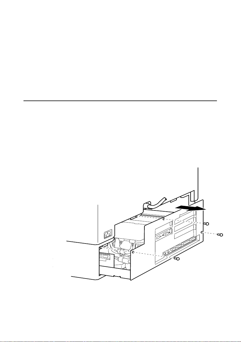
Handle static-sensitive items with extreme care. Hold expansion
•
cards and add-on components only by their edges, avoiding
their electrical contacts. Never touch the components or
electrical contacts on the motherboard or on expansion cards. In
general, do not handle static-sensitive items unnecessarily.
• Keep all conductive material, foodstuffs and especially liquids,
away from your work area and the open computer.
Opening the system unit
To pull out the LPX system cage:
1. Turn off the system unit.
2. Set the AC power outlet switch to its Off position.
3. Unplug the power cord from the rear of the system unit.
4. Unscrew the three screws (shown below), and put them safely to
one side.
Inside the System Unit
MS 530 OWNER’S HANDBOOK A/3
Page 73
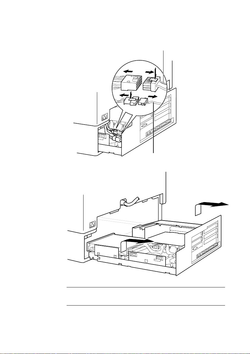
Inside the System Unit
5. Pull out the LPX cage so as to disconnect the two internal cables.
6. Gently pull out the remaining LPX cage.
Power Cable
Audio Cable
Note:
Remember to re-connect the two internal cables before re-fitting the LPX cage.
A/4 MS 530 OWNER’S HANDBOOK
Page 74
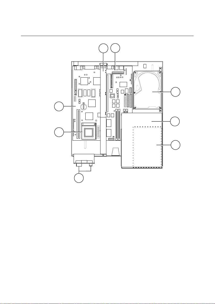
The components inside your computer
1
2
3
5
6
4
8
7
Inside the System Unit
1 System main board, for details see ‘Board Layout’.
2 System Processor
3 ‘Standby/Restore’ switch and LEDs.
4 Floppy disk drive, see Chapter 3 ‘Using the System Drives’.
5 CD-ROM drive, see Chapter 3 ‘Using the System Drives’.
6 Hard disk drive, see Chapter 3 ‘Using the System Drives’.
7 Rear audio sub-board.
8 Riser board, see Chapter 6 ‘Expansion Cards’.
MS 530 OWNER’S HANDBOOK A/5
Page 75
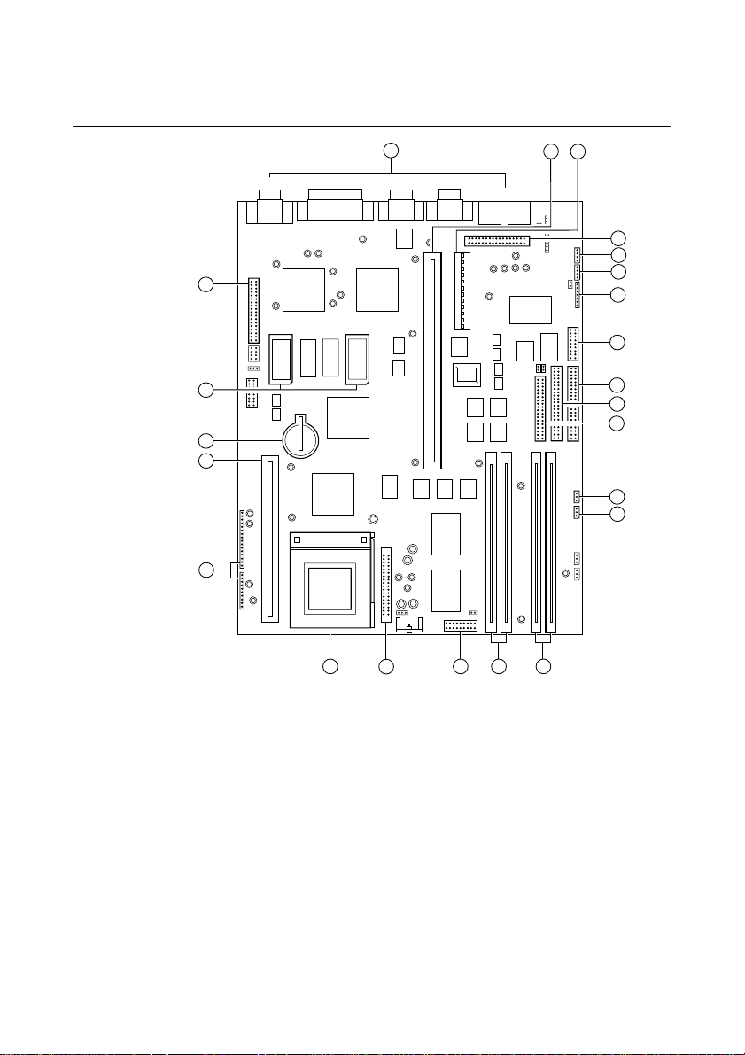
Inside the System Unit
21
20 2
3
1
19
18
17
15
14
Video
Parallel
Com 2
Com 1
Mouse Key/Bd
7
8
9
10
6
5
11
16
13
12
4
23
22
Board layout
1 Front audio connection 13 Riser board socket
2 SIMMs sockets 0, 1 14 External ports
3 SIMMs sockets 2, 3 (unavailable) 15 Video feature connection
4 Floppy ribbon connector 16 Video upgrade sockets
5 CD ribbon connector 17 CMOS Battery
6 HDD ribbon connector 18 Cache memory socket
7 Wave table connection 19 System connections
8 Modem audio connector 20 Processor ZIFF socket
9 TV audio connector 21 Power module
10 CD audio connector 22 BIOS jumper PL5
11 Rear audio connection 23 BIOS jumper PL6
12 Power connections
A/6 MS 530 OWNER’S HANDBOOK
Page 76

Jumper configurations
There are very few jumpers that will ever need changing, most of
them have been factory set for your system and its needs, but for
information the details are given here. Use the board layout view (on
the previous page) to identify the jumpers (detailed below). Some of
the jumpers may be hidden under the CD-ROM and floppy drive
and will therefore need to be removed in order to get to the jumper
switches. Refer to Chapter 5, “System Upgrades”, which details instructions on
how to remove the CD-ROM and floppy drives.
Internal ‘audio’ modem
PL4 Just along from the CD audio connection, default position
BIOS reprogramme
These links are for special purposes. Only to be used for an official
upgrade to the system BIOS. Do not move for any other reason.
PL5 Normal link 1 and 2. This link is in the event of a disaster
Inside the System Unit
if no internal modem is fitted, link pins 3 and 4. Remove
only when fitting an internal modem supporting sound.
occurring during an upgrade to the system BIOS. Link
moved to pins 2 and 3 will enable the system to be booted
up from an internal backup of the BIOS held in a secure
area in the system ROM.
PL6 Normal link 2 and 3, move to pins 1 and 2 to enable
Floppy disk control mode
PL13 Next to floppy disk ribbon connector, default position
Clear BIOS settings
PL21 Next to outer video upgrade socket, default position link
BIOS reprogramming (requires specialist software).
link pins 3 and 4. To enable 3-mode operation of the
drive (not usual in Europe), link 1 to 3, and 2 to 4.
pins 1 and 2. Moving the link to pins 2 and 3 disconnects
the battery from the BIOS memory, and will cause all the
MS 530 OWNER’S HANDBOOK A/7
Page 77
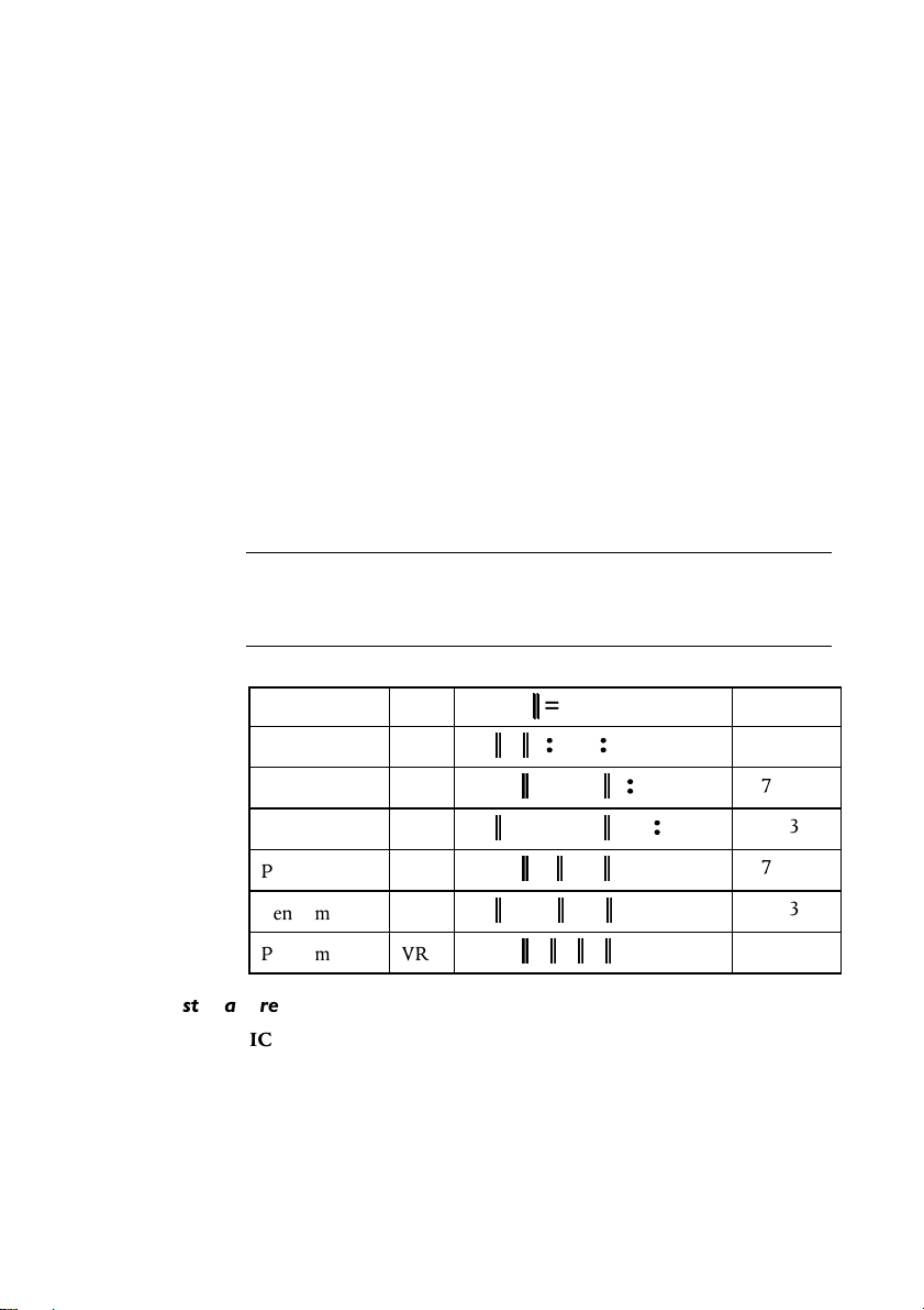
Inside the System Unit
user settings to be lost. To be used with caution and only
in the event of an access password being lost.
VESA option
A single jumper may be the only one fitted, at the end nearest PL21.
This would normally be removed if fitting a higher feature ‘plug in’
video card. It may not cause any problem if this link is inadvertently
left in during the upgrade but, if taken out, it must be replaced if the
extra video card is subsequently removed.
Processor and BUS clock
These settings must not be changed except in the event of a processor
upgrade. Full details of the processor’s required settings should
accompany the new processor and the appropriate board links
should then be identified from the table below.
Warning
Do not alter these links under normal circumstances as it could lead to the
destruction of the processor and/or other vital components on the board.
Processor Speed PL1
Pentium 75 VRE
Pentium 90 VRE
Pentium 100 VRE
Pentium 120 VRE
Pentium 133 VRE
Pentium 150 VRE
Soundblaster address
IC12 Near CD audio connector. Default position, link rear pins,
sets the on-board Soundblaster to address 220h. Removing
the link changes the address to 240h.
A/8 MS 530 OWNER’S HANDBOOK
SW1,
Pin 1
Pin 1
Pin 1
Pin 1
Pin 1
Pin 1
Link, = No link
=
MHz)
ISA (
8.33
7.5
8.33
7.5
8.33
7.5
Page 78
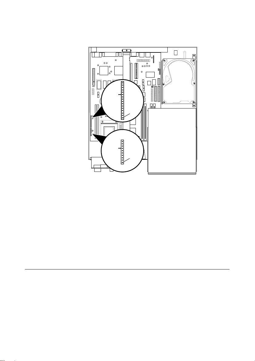
PL24, PL28
Inside the System Unit
PL28
Pin1
PL24
Pin1
This range of pins is not for jumpers, but is used to connect various
features around the system case to the motherboard.
PL24 Pins: 1 to 4 HDD active light
5 to 9 Keylock (not fitted)
10 & 11 System in ‘power standby’ light
12 & 13 System hardware reset (not fitted)
PL28 Pins: 1 & 2 System standby restore switch
3 to 7 Infra-red controller
8,9,10 Fan, slow mode (not used)
11,12,13 Fan, full speed mode (default)
Replacing the CMOS battery
The battery has an average life of 3-5 years. If you have to reconfigure the
computer every time you turn it on, the battery has discharged and
needs replacing. The battery is a 3 volt lithium type (CR2032 or equivalent).
MS 530 OWNER’S HANDBOOK A/9
Page 79

Inside the System Unit
To replace the battery
1. Turn off the computer and unplug the power cord.
2. Take suitable anti-static precautions and pull out the LPX system
cage. If you are unfamiliar with the recommended anti-static
precautions and/or the process of pulling out the LPX system
cage, refer to beginning of this Chapter for detailed instructions.
3. Identify the battery holder from the diagram of the motherboard.
4. Carefully disconnect and remove any expansion cards that may
obstruct easy access to the battery.
Warning
Do not
metal or other conductive implement to remove the battery. If
use a
a short-circuit is accidentally made between its positive and negative
terminals, it may cause the battery to explode.
5. Lift the edge of the battery far enough to clear the base of the
holder, then slide the battery from under the contact spring.
6. Check the replacement battery is identical to the old battery.
7. Taking care not to touch the top or bottom surface of the battery,
pick up the replacement with the positive (+) terminal upwards.
8. Slide the battery into the holder from the same side the old
battery was removed.
9. Replace any expansion cards you had to remove in step 4.
10. Refit the LPX system cage.
11. Dispose of the old battery according to the makers instructions.
When you turn on the computer you will have to run the BIOS Setup
utility to re-enter the hardware configuration. If in any doubt refer
to Appendix B, “System BIOS and Setup”.
A/10 MS 530 OWNER’S HANDBOOK
Page 80

System BIOS and Setup
B SYSTEM BIOS AND SETUP
When the system is switched on, the Power on Self Test (POST)
does its job depending upon the information it finds in the BIOS
and sets up the computer to boot into operation. You can access the
BIOS and check or alter the configuration via its setup utility.
Caution
The BIOS has been set in our factory for the optimum system performance and
operation. It is not advisable to alter any settings under normal use.
MS 530 OWNER’S HANDBOOK B/1
Page 81
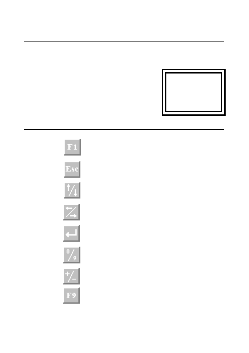
System BIOS and Setup
Entering Setup
During, or just after, the POST, a small box appears in the top right
corner of the screen. It looks like this:
While this is on the screen press
[F1] on the keyboard, and in a few
seconds you will be presented with
the BIOS setup screen. This is the
only way in which you can enter the
setup utility.
Control keys
Provides help on the highlighted topic, pressing it again
transfers you to the general help pages.
Exit either the setup, or go back a page if in a sub-menu.
~~~~ ~~~
~~~~ ~~~
~~~~ ~~~
Scroll through a menu list.
To toggle values or settings.
The enter key, to select the highlighted item.
Numbers, used in places where values are to be entered.
Used when required, similar to numbers.
Restores the original settings that you entered with.
B/2 MS 530 OWNER’S HANDBOOK
Page 82

To restore the original default setting
Warning
F9 will not restore the date settings and pressing F10 may put in a default setting
that could have been changed by our factory during production build and test.
We recommend that you make a note of ALL of the settings before any
changes are made.
If Setup runs on its own
This can happen for three reasons.
• There is a configuration error, or fault. In which case an error
message may well appear. A list of these is given at the end of
this chapter.
• The BIOS battery may be running down. In this case you may
also get error messages. If it happens every time you boot up,
you may have to change the motherboard battery. Instructions
for this are given in Appendix A, “Inside the System Unit”.
System BIOS and Setup
• The system’s configuration may have been changed. More
system memory, more cache memory, or an upgrade that uses
ISA interrupts etc.
If you are unable to resolve any problem, do not alter too many
settings, but make a note of them and any error messages that
appeared on the screen and call your Apricot dealer or authorised
maintainer.
MS 530 OWNER’S HANDBOOK B/3
Page 83

System BIOS and Setup
Opening screen
On entering the setup utility a main menu screen appears. If there is
an associated sub-menu, or a further sub-menu available, then the
listed options have a preceding bullet, as shown below:
• System summary Information about the system.
• Devices and I/O ports The settings for serial, parallel ports,
• Date and time Change the system master clock
• Security View or change access to HDD, user
• Start options Boot from A: or C:, keyboard speed,
• Advanced setup Change the cache settings, ROM
• ISA Legacy resources Register resources used by new ISA
Processor, memory, drives etc.
IDE interfaces, HDD.
and administrator passwords.
POST speed etc.
shadowing and other related topics.
expansion cards, memory, DMA,
interrupts etc.
• Power management Change settings for the Low power and
Save settings Saves any changes that have been made
Restore settings Restores all the settings to the values
Load default settings Restores the settings to their default
Exit setup Ends the session and starts the system
B/4 MS 530 OWNER’S HANDBOOK
Standby energy saving modes.
that were in force when you entered
setup, same as pressing F9
(possibly blank) state. CAUTION-Some of the settings may have been
altered during factory build or test.
POST again. You will be asked to save
any new settings.
Page 84

Sub-menu pages
System summary
This page cannot be edited, but gives a summary of the system main
settings. Changes made in other pages will be reflected here. Make a
note of the information on this page before you progress any further
or make any changes.
Devices and I/O ports
Serial ports 1 & 2 (COM1 & COM2)
Selects the I/O ports and interrupts used by the two serial ports.
Normally set to default settings. Do not disable the serial ports
unless you are absolutely sure you are not going to need them.
Parallel port
This sets the I/O port and interrupt used by the parallel port. You
can select standard, or extended port modes. To obtain the extended
port modes it will be necessary to change the I/O setting.
System BIOS and Setup
Standard mode Output only.
Extended mode Bi-directional Simple two way data.
EPP Enhanced parallel port
compatible operation.
ECP Extended capabilities port
operation.
Any parallel port devices that you may wish to attach, such as a tape
streamer or external hard drive etc., will have full instructions
supplied with them that will tell you if the port capabilities need to
be altered to one of the extended options above.
Mouse
This tells the system that a mouse is connected to the mouse port.
The mouse is then detected by the POST. You should not normally
change this setting.
MS 530 OWNER’S HANDBOOK B/5
Page 85

System BIOS and Setup
Floppy disk drives
This is available purely to change the mode of the floppy drive. The
drive supplied and fitted is a 3.5” 1.44 Mbyte. This setting, if
changed, could prevent software access to the fitted drive.
Hard disk drive
Hard disk type is auto detected on switch on.
HDD 0 The system hard drives are normally attached to
HDD 1 the primary PCI IDE interface. The system is
Selecting either of the HDD will put you into a further sub-menu
where their settings can be changed;
Performance Select either Compatible or High performance
Transmission Select either Extended or Standard
Mode Default setting: Extended
CD-ROM drive
supplied with a master HDD (HDD 0)
Default setting: High performance.
CDROM 2 The CD-ROM drives are included in this section
CDROM 3 as most new types are controlled from the
Selecting either of the CDROM will put you into their sub-menu
where the changeable setting for these drives is for;
Performance Select either Compatible and High performance
Date and Time
This is to enable a change to the Real Time Clock (RTC) on the
system motherboard. This RTC is normally maintained by the
motherboard battery when the system is switched off.
B/6 MS 530 OWNER’S HANDBOOK
secondary IDE interface
Default setting: Compatible
Page 86

System security
System BIOS and Setup
System time
Using the left and right arrow keys to move around, you then use
either the number keys to insert new figures or the + and - keys to
increase/decrease the existing number. The time is in 24 hour
format.
System date
The procedure is the same as setting the time, the date being in UK
format of Day / Month / Year, e.g. 1st August 95 = 01 / 08 / 1995
This is to allow you to set, change or delete a set of passwords for
either user or administrator, plus control access independently to
HDD and floppy drives.
Caution
This menu can have interaction with the START OPTIONS menu. You must
ensure that a user has access to a STARTUP DEVICE, or the user could be
denied access to the system completely.
User password
If a user password is enabled , the correct password must be entered
every time the system is switched on or re-booted. If you select this
option a sub-menu appears:
Enter User Password Type in your password, use numbers
and letters only.
Enter Password Again Re-type it as above.
Set Or Change Select this to accept the password for
all future sessions.
If you have not changed or entered a password before selecting ‘Set
Or Change’, a box will appear asking you to press ENTER to
confirm deletion of the existing password, effectively choosing ‘no
password’. If you make any mistakes, press ‘Esc’ to return to the
main menu and start again.
MS 530 OWNER’S HANDBOOK B/7
Page 87

System BIOS and Setup
Delete User password
Use this to clear or remove the existing password, without replacing
it with a new one. You may be asked for confirmation or to enter
the old password.
Warning
Remember your passwords, But do not write them down on a piece of paper
and leave it in your desk drawer, or pin it on your wall!
Password prompt
The system can be set to ‘ask’ for the password on switch on or reboot. You may not wish to have a prompt for security reasons, but
the user is still required to enter a password.
Administrator Password
This allows the setting of a supervisory password and to choose
whether a user can change their individual password. This
administrator password will be required in order to enter the BIOS
Setup. If the user password is entered instead, there is only access to
the System Summary and (if enabled) access to setting the User
Password of System Security.
The procedure is generally the same as for the User Password, with
the addition of User Password changeable by User. Select either
Yes or No for this feature.
Start Options
Certain features can be set or enabled for system boot up.
Keyboard Numlock (The default Is ON
If ON, the keyboard number lock is enabled when the system boots
and the right hand section of the keyboard is numbers only.
Keyboard speed (The default is FAST)
This sets the speed at which a pressed key will repeat.
B/8 MS 530 OWNER’S HANDBOOK
)
Page 88

System BIOS and Setup
Disketteless Operation
If this option is Disabled, POST will report a fault or any absence of
the floppy drive and halt the boot process. If Enabled, POST will
bypass the floppy test and continue, providing another boot device
is available e.g. HDD.
Displayless Operation
If this option is Disabled, POST will halt on any absence of a
monitor, Enabled, will allow the system to start without a monitor
e.g. when used as a small fileserver.
Keyboardless Operation
Similar principle to the above.
Start-up Devices
This allows the choice of sequence that the BIOS uses to look for a
‘boot’, drive. The default sequence is:
Diskette drive 0; Hard disk 0 (i.e. A: then C:)
Advanced Setup
It should not need to be changed for normal operation.
Power On Self Test (The default is ENHANCED)
The POST can be selected to either run only a short set of tests
(Quick) or a full test (Enhanced).
Virus Detection
When Enabled, the BIOS will perform a checksum operation on the
boot sector to find if a ‘boot virus’ has crept in. It is not an infallible
check against the newer types of virus, but it may help.
Any settings changed here, if incorrect, may cause the system to halt
or may cause your software to malfunction. A warning to this effect
appears on the screen as you enter this item from the menu.
MS 530 OWNER’S HANDBOOK B/9
Page 89

System BIOS and Setup
Cache Control
A simple two line screen allows you to either enable or disable the
L2 cache memory (external to the processor).
The default setting is Enabled, and should not normally be
changed. Some of the older software is however, speed sensitive and
on rare occasions you may need to disable the L2 cache.
Cache Size
This value also appears in the System Summary. It is detected by the
POST and the value is not editable.
ROM Shadowing
The contents of the Read Only Memory are copied into the faster
Random Access Memory during start-up. Choosing this option displays a
sub-menu showing a split up table of the memory address range,
with the range sectioned into 32K blocks. Some areas are greyed out
as they are already in use by parts of the system.
Changes should only be made to the supplied settings when fitting a
new expansion board, if asked to do so, and then with great care,
using the information supplied with the particular card.
ISA Legacy Resources
When expanding your system with an ISA card this menu section is
used to ‘register’ the system resources that the card uses. This needs
to be done as the system cannot auto-detect their being in use, but
must be told about them so as to auto-configure any PCI or ISA
Plug and Play cards and avoid conflicts. There is a menu for each topic.
The resources affected are; Memory, I/O port addresses, DMA
channels, System interrupts.
Some areas are shown as Allocated by the system and are only for your
information. Each resource can be set to either Available or Not available.
If shown as available, it is assumed by the system not to be in use by
any ISA card or device and therefore will be made available for the
PCI auto-configure process.
B/10 MS 530 OWNER’S HANDBOOK
Page 90

Although many ISA cards are very simple to configure, the resources
they use, if any, MUST be registered in the BIOS.
Power Management
NOTE
Read also the information in the Help topics within the Apricot Power
Management program in Windows before attempting any changes.
The adjustable settings available here will be dependent upon your
system configuration. We recommend to make the adjustments to
events and timings within the Apricot software in Windows. That
will allow use of the Media Manager software to pre-program
restore events and operations.
If timings etc., are available for editing, they will have been pre-set
in our factory to ensure compliance with the Energy Star
Programme, but timing changes, or disabling the features, are both
straightforward, either in the software or the BIOS.
Energy Saving is initially set as a two stage operation. First there is a
‘Low Power’ mode. The monitor will blank, plus certain components
inside the system will slow down or stop. The system is restarted by
events, such as mouse or keyboard activity, NOT by pressing the
standby button.
System BIOS and Setup
Second stage is ‘Standby’, where the monitor is in a controlled ‘off’
state, the processor halts, the HDD will spin down, the fans may
stop and the whole system enters a state where it will typically be
consuming less than 20W. The system is restarted by pressing the
‘standby’ button on the system front panel.
Depending upon the system’s configuration, certain events will
trigger ‘intermediate’ states, e.g. e-mail will start up the appropriate
sections of the system, deal with the message, then return to standby.
MS 530 OWNER’S HANDBOOK B/11
Page 91

System BIOS and Setup
Error Messages
The following table lists errors which will be detected by the POST routine. The
possible cause is listed with the error code. If you get an error which is not listed and
the problem persists, call your supplier or authorised maintainer.
Code Cause Code Cause
Timer tick interrupt failure
101
Timer 2 test failure
102
Diskette controller failure
106
Systemboard memory parity interrupt
110
Option ROM checksum failure
114
Real time clock failure
151
Real time clock battery failure
161
CMOS RAM checksum failure
162
Invalid configuration information
162
Time of day not set -preboot
163
Memory size does not match CMOS
164
Bad EEPROM CRC #1
175
System tampered
176
Bad PAP checksum
177
EEPROM is not functional
178
PAP update required
183
Bad POP checksum
184
Corrupted Boot sequence
185
Hardware problem
186
Excessive password attempts
189
Base memory error
201
External cache failure
229
301
301
301
604
604
605
662
762
1762
1780
1781
1782
1783
1800
1801
1802
1803
1804
1805
1962
2400
2462
Keyboard clock line failure
Keyboard data line failure
Keyboard stuck key failure
Diskette drive 0 failure
Diskette drive 1 failure
Diskette unlocked problem
Diskette drive configuration
Coprocessor configuration
Hard disk configuration
Fixed disk 0 failure
Fixed disk 1 failure
Fixed disk 2 failure
Fixed disk 3 failure
No more IRQ available
No more room for option ROM
No more I/O space available
No more memory <1Mb available
No more memory >1MB available
Checksum error or 0 size option ROM
No bootable device
Display adapter failed; using alternate
Video configuration
B/12 MS 530 OWNER’S HANDBOOK
Page 92

Technical Information
C TECHNICAL INFORMATION
This appendix provides some technical information about the
computer. More detailed information can be obtained from your
supplier.
MS 530 OWNER’S HANDBOOK C/1
Page 93

Technical Information
Specifications
General
Processor Type Intel Pentium 75MHz upwards
Bus speeds 50, 60, 66 Mhz
Chipset Intel Triton
BIOS ROM Surepath 1.3 1 Mb Flash programmable.
Memory Simms 32-bit, parity not required, (One pair of
SIMM socketss obstructed by CD-ROM drive
therefore only one pair available, limiting
memory expansion to a maximum of 64 Mb).
Video Chipset Cirrus Logic CL-GD543x/PCIlocal bus
Video RAM 1 Mb onboard upgradeable to2 Mb
Resolutions EVGA 1280 x 1024
EVGA 1024 x 768
SVGA 800 x 600
VGA 640 x 480
Cache Modules (L2) Write-back, pipeline burst or async 256 Kb
or 512 Kb modules with integral Tag RAMs.
Audio On board Creative Labs 16 Bit
Yamaha OPL3 synthesiser.
I/O ports Serial Two 9-way male D-Type RS-232
(Will be used by the IR sensor for the remote).
Parallel 25-way female D-type. EPP/ECP compatible.
Keyboard 102 key AT-compatible
Mouse PS/2-compatible two-button
Hard disk interface Dual AT-Attachment/Enhanced IDE
Hard disk drive bay Capacity One 1.6” drive (Limitation of fitting one
hard disk only to system).
Expansion Riser board The riser board fitted supports the expansion
of 5 cards:
ISA one full length and
two half length
PCI two half length
C/2 MS 530 OWNER’S HANDBOOK
Page 94

Floppy disk drive (Mitsubishi MF355F)
Power Connector 4 pin miniature
Loading 1.5W during read/write 100mW during
Disk formats (3 Mode) DS-DD 720 Kb, 1.2 Mb (NEC, Japan), HD 1.44 Mb
Reliability MTBF Estimate, 80.000 hours
ATA-API CD-ROM drive (Sony CDU77E)
Discs Acceptable discs CD-ROM mode 1 data discs
Disc diameter 12cm, 8cm
Transfer rate Sustained 600 Kbyte/s (Mode 1)
Burst 4.0 Mbyte/s
Speed Quadruple 600 Kb/s typical mode 1
Access time 190 ms average
Technical Information
standby (400ms start time)
CD-ROM mode 2 data discs
CD audio discs
Audio-combined CD-ROM
Multisession Photo CD
682 Kbytes (Mode 2)
400 ms full stroke
Audio output Line 0.75 V at 47 kOhm
Headphones 0.55 V at 32 Ohm
Host interface ATA-API
Power specification Voltage +5 V dc +5%
+12 Vdc +10%
Ripple +5 V: 100 mVp-p
+12V: 200 mVp-p
Current (max) +5 V: 1000 mA
+12 V: 1500 mA
Reliability MTBF 100,000 power -on hours
Laser Type GaAIAs semiconductor
Wavelength 780 nm
Output power 0.6 nW
MS 530 OWNER’S HANDBOOK C/3
Page 95

Technical Information
Warning
The laser beam inside the CD-ROM drive is harmful to the eyes if looked at
directly. Do not attempt to remove the drive cover or otherwise disassemble the
CD-ROM drive. If a fault occurs, call an authorised maintainer.
Physical Characteristics
Weight and dimensions
Component Height Depth Width Weight
System unit 425 mm 445 mm 430mm 40 Kg
Keyboard 40 mm 205 mm 488 mm 1.4 Kg
Warning
Be careful when lifting the system unit as it weighs approximately 40Kg with
its various components inside.
Temperature and Humidity ranges
Range Temperature Relative humidity with no
Storage/Transport -5 to +45OC 10% to 90%
Operational +5 to +35OC 30% to 80%
Voltage range
Setting AC Voltage Frequency
230V 220 to 240V 50 to 60 Hz
Warning
The power cord supplied with the system complies with the safety standards
applicable to the country in which it was originally sold. You should consult an
Apricot dealer before using the system in another country .
C/4 MS 530 OWNER’S HANDBOOK
condensation
Page 96
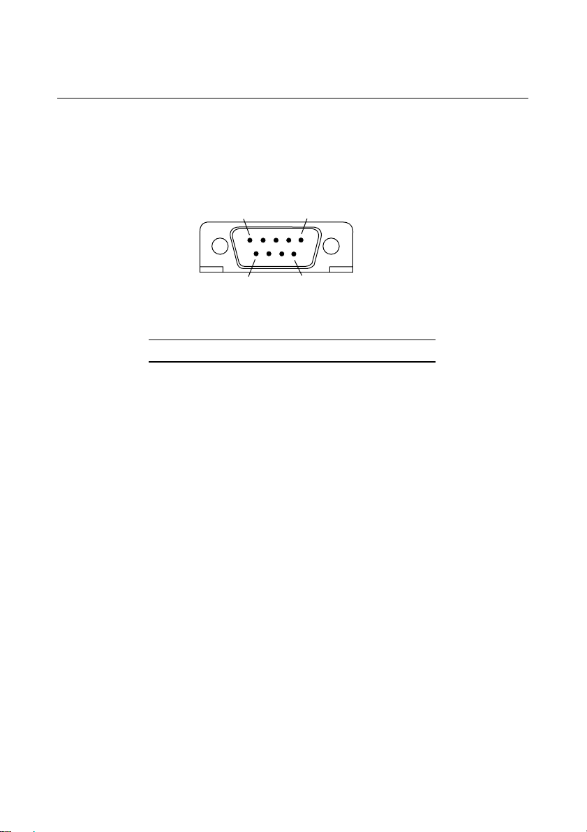
Port Characteristics
51
6
9
10101
Serial port
9-way male D-type (COM1/COM2)
Pin I/O Function
1 I Data carrier detect
2 I Receive data
3 O Transmit data
Technical Information
4 O Data terminal ready
5 - Signal ground
6 I Data set ready
7 O Request to send
8 I Clear to send
9 I Ring indicate
MS 530 OWNER’S HANDBOOK C/5
Page 97

Technical Information
Parallel port
25-way female D-type
13
25
14
Pin I/O Function
1 I/O - STROBE
2 I/O Data bit 0
3 I/O Data bit 1
4 I/O Data bit 2
5 I/O Data bit 3
6 I/O Data bit 4
7 I/O Data bit 5
8 I/O Data bit 6
9 I/O Data bit 7
10 I - ACK
11 I BUSY
12 I PE
13 I SLCT
14 O - AUTO FEED
15 I - ERROR
16 O - INIT
17 O - SLCT IN
18 - Ground
19 - Ground
20 - Ground
21 - Ground
22 - Ground
23 - Ground
24 - Ground
25 - Ground
1
C/6 MS 530 OWNER’S HANDBOOK
Page 98

Monitor port
Technical Information
15-way female D-type (VGA)
5
10
15
1
6
11
Pin I/O Output Monochrome Colour
1 O Red No pin Red
2 O Green Mono Green
3 O Blue No pin Blue
4 - Reserved No pin No pin
5 - Digital G Self test Self test
6 - Red Rtn Key pin Red Rtn
7 - Green Rtn Mono Rtn Green Rtn
8 - Blue Rtn No pin Blue Rtn
9 - Plug No pin No pin
10 - Digital G Digital G Digital G
11 - Reserved No pin Digital G
12 - Reserved Digital G DDC Data
13 O Hsync Hsync Hsync
14 O Vsync Vsync Vsync
15 - Reserved No pin DDC Clock
Red Rtn, Green Rtn, Blue Rtn = Analog grounds
Digital G = Digital ground for sync returns and self test.
MS 530 OWNER’S HANDBOOK C/7
Page 99
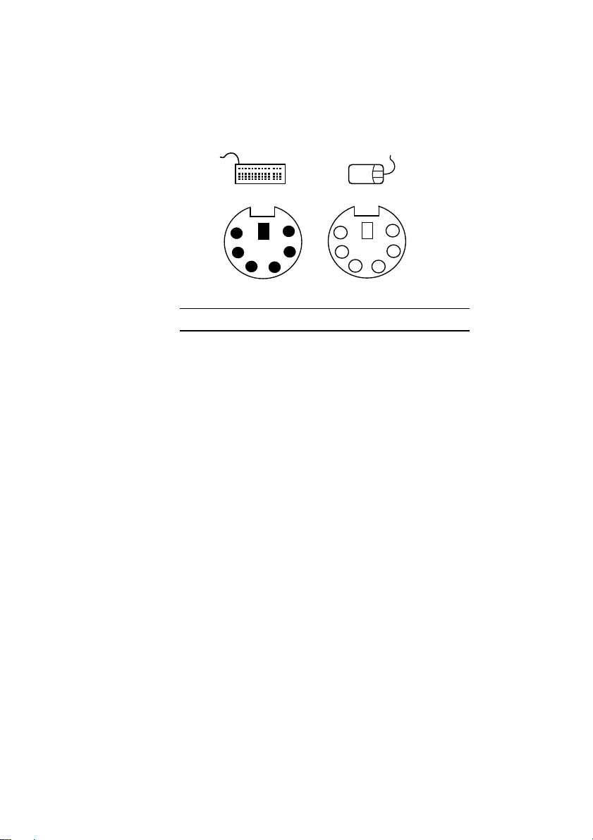
Technical Information
Keyboard and mouse port
6-pin minature DIN connector
Pin I/O Function
1 I/O Data
2 - Reserved
3 - Ground
4 - + 5 Vdc
5
3
1
2
6
4
6
4213
5
5 I/O Clock
6 - Reserved
The voltages and signals are the same for both connectors.
Although the keyboard and mouse ports are physically and
electrically compatible, neither the keyboard nor the mouse will
operate if plugged into the other’s socket.
C/8 MS 530 OWNER’S HANDBOOK
Page 100

MITSUBISHI ELECTRIC
APRICOT COMPUTERS LIMITED
3500 PARKSIDE
BIRMINGHAM BUSINESS PARK
BIRMINGHAM B37 7YS
UNITED KINGDOM
APRICOT COMPUTERS LIMITED
TRAVELLERS LANE
HATFIELD
HERTFORDSHIRE AL10 8XB
UNITED KINGDOM
MITSUBISHI ELECTRIC EUROPE GmbH
GOTHAER STRASSE 8
POSTFACH 1548
40835 RATINGEN
DEUTSCHLAND
 Loading...