

Page 1

CT104 Manual
Rugged Enclosure System
for Embedded
PC/104 Systems
Manufactured by
TRI-M ENGINEERING
Engineered Solutions for Embedded Applications
Technical Manual
P/N: CT104-MAN
Revision: 08/10/03
TRI-M ENGINEERING
1407 Kebet Way, Unit 100
Port Coquitlam, BC V3C 6L3
Canada
http://www.Tri-M.com
Tel 604.945.9565
North America 800.665.5600
Fax 604.945.9566
Page 2

08/10/2003 CT104 Manual
CHAPTER 1: INTRODUCTION............................................................................................................4
1.1 DESCRIPTION ...................................................................................................................................................................................4
1.2 FEATURES:.......................................................................................................................................................................................5
1.3 CAN-TAINER KIT INCLUDES: ...........................................................................................................................................................6
CHAPTER 2: CUSTOM BOARD MOUNTING .....................................................................................6
CHAPTER 3: CAN-TAINER MATERIAL SPECIFICATIONS...............................................................7
3.1 ALUMINUM HOUSING MATERIALS...................................................................................................................................................7
3.2 RUBBER MOUNTING MATERIALS.....................................................................................................................................................8
Tri-M Engineering Tel: 800.665.5600, 604.945.9565
1407 Kebet Way, Unit 100 Fax: 604.945.9566
Port Coquitlam, BC V3C 6L3 E-mail: info@tri-m.com
Canada Web site: www.tri-m.com
2
Page 3

08/10/2003 CT104 Manual
PREFACE
This manual is for integrators of applications of embedded systems. It contains information on
hardware requirements and interconnection to other embedded electronics.
DISCLAIMER
Tri-M Engineering makes no representations or warranties with respect to the contents of this
manual, and specifically disclaims any implied warranties of merchantability or fitness for any
particular purpose. Tri-M Engineering shall under no circumstances be liable for incidental or
consequential damages or related expenses resulting from the use of this product, even if it has been
notified of the possibility of such damages. Tri-M Engineering reserves the right to revise this
publication from time to time without obligation to notify any person of such revisions. If errors are
found, please contact Tri-M Engineering at the address listed on the title page of this document.
COPYRIGHT © 2000-03-22 TRI-M ENGINEERING
No part of this document may be reproduced, transmitted, transcribed, stored in a retrieval system, or
translated into any language or computer language, in any form or by any means, electronic,
mechanical, magnetic, optical, chemical, manual, or otherwise, without the express written permission
of Tri-M Engineering.
Tri-M Engineering Tel: 800.665.5600, 604.945.9565
1407 Kebet Way, Unit 100 Fax: 604.945.9566
Port Coquitlam, BC V3C 6L3 E-mail: info@tri-m.com
Canada Web site: www.tri-m.com
3
Page 4

08/10/2003 CT104 Manual
CHAPTER 1: INTRODUCTION
1.1 Description
Tri-M's PC/104 Can-Tainer is a new and unique design specifically intended to protect PC/104
electronics such as instrumentation, data collectors, remote terminals, SCADA packages or other
solutions that operate in hostile environments. The Can-Tainer is constructed of 0.125” aluminum
and can accommodate any number of PC/104 modules, their cabling and peripherals, with maximum
flexibility in a minimum amount of space. Surprisingly, these units are also priced to be used
anywhere embedded electronics require a black box.
When deploying electronics in mobile or vehicle applications, vibration and G-forces can greatly
reduce their life expectancy and reliability. The Can-Tainer™ ensures the PC/104 modules receive
maximum protection from vibration and G-forces. This is accomplished using Tri-M's dual system of
isolating and absorbing rubber mountings. Internally, each of the four corners of the PC/104 stack is
held in place by a rubber corner system, which isolates the PC/104 cards from the extruded
aluminum enclosure as it absorbs high frequency vibration. Externally, the anodized aluminum
enclosure mates with a thick rubber-mounting pad allowing the Can-Tainer™ to be attached to a
bulkhead while it absorbs low frequency G-forces. The rubber pad is optional and may be removed.
A wide variety of end caps are available for the Can-Tainer including openings for DB9, DB15, DB25
and RJ45s. Custom end caps with any combination of connector holes can be supplied to meet
specific client requirements. The Can-Tainer is NEMA rated when used with optional end cap
gaskets and appropriate end cap and connectors. Each anodized aluminum end cap is securely
attached to the housing with eight self-tapping, hex head machine screws. The standard black
anodized Can-Tainer measures 5.4" x 6.0" (L x W) and comes in five standard heights of 4", 6", 8",
10" and 12". The Can-Tainer Kit includes one solid end cap with no I/O openings (Part # CTEC00),
one I/O end cap with openings for four DB9s & two DB25s (Part # CTEC01), sixteen end cap screws,
and one mounting kit. The mounting kit has two gaskets, four rubber corner guides, eight rubber
corner stops, one tube of CA glue and one external thick rubber anti-shock mounting pad.
To mount boards or items such as hard drives that are larger than 3.550” x 3.775”, use the optional
CTn-VD00 mounting plates. These install into rails that run the length of the enclosure. For smaller
items, an optional PC/104-size aluminum plate, CT-AL00, enables you to mount accessories directly
onto the PC/104 stack.
An optional fan kit (CT-FAN) provides forced air-cooling. To provide airflow through the Can-Tainer,
drill intake holes at the point where the fan is mounted and exhaust holes at one additional location
(usually at one end cap). For a sealed environment with only conduction cooling, the fan may be
mounted offset from the enclosure wall using custom hardware.
The Can-Tainer cross-section measures 6.00” wide by 5.45” high (not including mounting pad). It is
available in seven standard lengths of 2”, 4”, 5”, 6”, 8”, 10”, and 12” (order no. CT-n where n = length
in inches). To calculate the height of your PC/104 stack, refer to the table ****. To compute the
length of the Can-Tainer needed, add the appropriate room at each end for cabling. Usually about
one inch of additional room is needed at any end that will have one or two cables, up to two inches for
more cables, depending on how the cables are routed inside the enclosure.
Tri-M Engineering Tel: 800.665.5600, 604.945.9565
1407 Kebet Way, Unit 100 Fax: 604.945.9566
Port Coquitlam, BC V3C 6L3 E-mail: info@tri-m.com
Canada Web site: www.tri-m.com
4
Page 5

08/10/2003 CT104 Manual
1.2 Features:
o Rugged anodized aluminum
o Securely holds PC/104 modules
o Internal stack vibration mount
o External isolating shock mount
o I/O end caps
o NEMA sealed with end cap gaskets
o PC/104 Can-Tainer available sizes in 2", 4", 5", 6", 8", 10" and 12"
o Custom sizes available
Figure 1 : Corner Mounting Rubber
Tri-M Engineering Tel: 800.665.5600, 604.945.9565
1407 Kebet Way, Unit 100 Fax: 604.945.9566
Port Coquitlam, BC V3C 6L3 E-mail: info@tri-m.com
Canada Web site: www.tri-m.com
Figure 2: Can-Tainer with PC/104 Card
5
Page 6

08/10/2003 CT104 Manual
1.3 Can-Tainer Kit Includes:
o 1x Can -Tainer body 2", 4", 5", 6", 8", 10" or 12"
o 1x CT-EC00, Solid End cap
o 1x CT-EC01, End cap with 4x DB9 and 2x DB 25
o 1x Anti-shock mounting pad
o 2x CT-EC gaskets
o 4x Corner guides
o 8x Corner rubber stops
o 1x Tube CA glue
o 16x End cap screws
Figure 3: Cross Section of Shock Mount Pad
CHAPTER 2: Custom Board Mounting
PC/104 modules may be mounted horizontally method (HM) or vertically method (VM). In the HM
method, the PC/104 modules are securely held by the rubber corner system. Accessory
equipment, such as batteries and transmitters, may be attached to a PC/104-AL mounting plate
and included in the PC/104 stack.
# Boards 1st Board / Non-Stackthrough 1st Board / Stackthrough
1 0.62 0.92
2 1.26 1.58
3 1.92 2.24
4 2.58 2.90
5 3.25 3.57
6 3.91 4.23
7 4.57 4.89
8 5.23 5.55
9 5.89 6.21
10 6.56 6.88
Tri-M Engineering Tel: 800.665.5600, 604.945.9565
1407 Kebet Way, Unit 100 Fax: 604.945.9566
Port Coquitlam, BC V3C 6L3 E-mail: info@tri-m.com
Canada Web site: www.tri-m.com
6
Page 7

08/10/2003 CT104 Manual
For the VM method, the PC/104 stack is mounted to a vertical divider, CT6-VD00 or
CT8-VD00. The vertical divider with the PC/104 stack installed is then slid into the
vertical card slots in the Can-Tainer™ case. Accessory equipment, such as batteries and
transmitters, may be attached to the opposite side of the vertical divider.
CHAPTER 3: Can-Tainer Material Specifications
3.1 Aluminum Housing Materials
Alloy - 6063-T5 Aluminum Extrusion
Finish - Black Anodized. Other finishes available.
Table C:
Typical Properties of 6063-T5 Aluminum Extrusion Alloy*
Physical Property Value
Average Coefficient of Thermal
Expansion
13.0 µin/°F (68° - 212 °F)
Approximate Melting Range 1140°F - 1210°F
Thermal Conductivity
1450 BTU - in/ft² hr °F (@
77°F)
Electrical Resistivity 2.8 µOhm-cm (@ 68°F)
Ultimate Strength 27,000 PSI
Yield Strength 21,000 PSI
12%
Elongation
(% in 2 in, 1/16" thick
specimen)
Hardness Brinell No.
60
(500 kg load, 10 mm ball)
Ultimate Sheer Strength 17,000 PSI
10,000 PSI
Fatigue Endurance Limit
(500 x 106 cycles Moore
Mach.)
Modulus of Elasticity 10 (106 PSI)
* Source: Aluminum Standards and Data, 1988 Aluminum
Association Inc.
Tri-M Engineering Tel: 800.665.5600, 604.945.9565
1407 Kebet Way, Unit 100 Fax: 604.945.9566
Port Coquitlam, BC V3C 6L3 E-mail: info@tri-m.com
Canada Web site: www.tri-m.com
7
Page 8
08/10/2003 CT104 Manual
3.2 Rubber Mounting Materials
Compound - High Grade EPDM 80 extruded rubber
Rating - ULHB94 Horizontal Burn Test, compound # 295-104-02-90
ETHYLENE PROPYLENE COPOLYMER (EPM/EPDM) Elastomers prepared from ethylene and propylene
monomers , at times with a small amount of a third monomer (Etlylene Propylene Terpolymer). Excellent
resistance to phosphate ester type hydraulic fluids.
Specific gravity..........................................86
Tensile Strength.........................................3,000
Elongation, max.........................................6x
Hardness, Shore A.....................................30-90
Brittle Point (F)..........................................-90
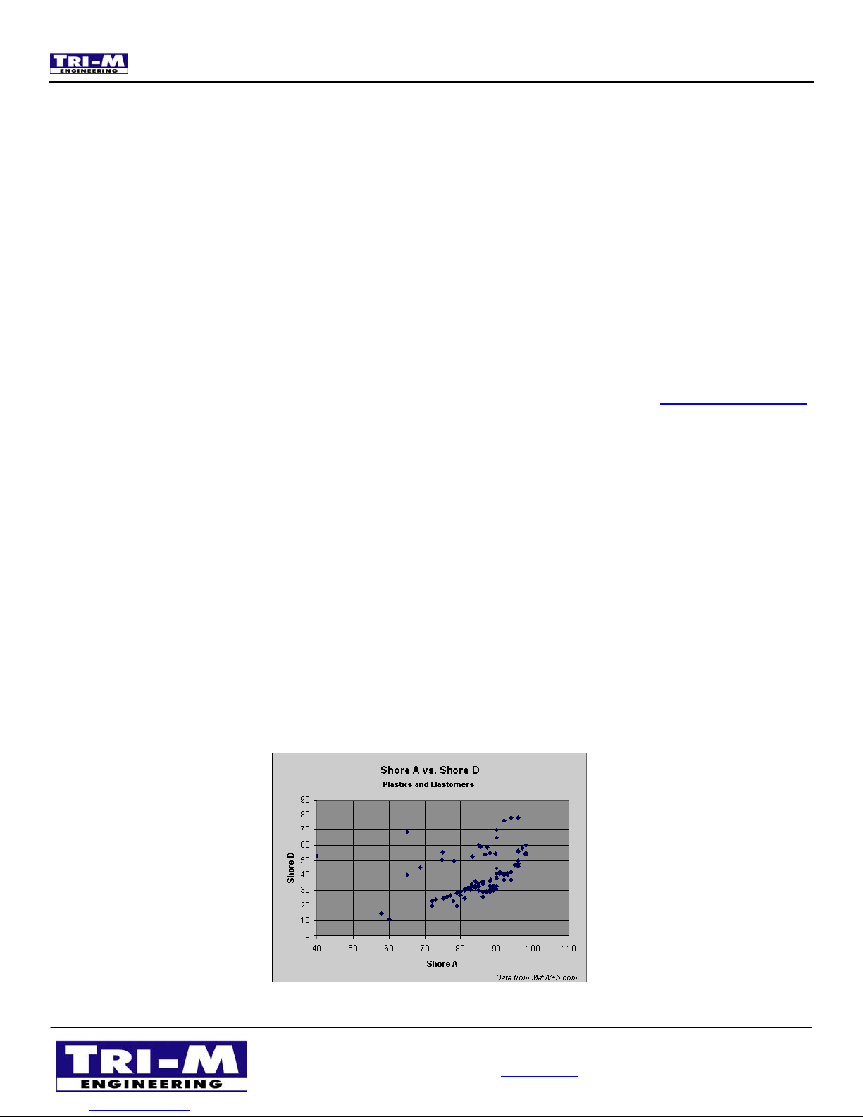
The hardness testing of plastics is most commonly measured by the Shore (Durometer) test or Rockwell hardness test.
Both methods measure the resistance of the plastic toward indentation. Both scales provide an empirical hardness value
that doesn't correlate to other properties or fundamental characteristics. Shore Hardness, using either the Shore A or
Shore D scale, is the preferred method for rubbers/elastomers and is also commonly used for 'softer' plastics such as
polyolefins, fluoropolymers, and vinyls. The Shore A scale is used for 'softer' rubbers while the Shore D scale is used for
'harder' ones.
The Shore hardness is measured with an apparatus known as a Durometer and consequently is also known as
'Durometer hardness'. The hardness value is determined by the penetration of the Durometer indenter foot into the
sample. Because of the resilience of rubbers and plastics, the hardness reading my change over time - so the indentation
time is sometimes reported along with the hardness number. The ASTM test method designation is ASTM D2240 00.
Related methods include ISO 7619 and ISO 868; DIN 53505; and JIS K 6301, which was discontinued and superseded
by JIS K 6253.
The results obtained from this test are a useful measure of relative resistance to indentation of various grades of
polymers. However, the Shore Durometer hardness test does not serve well as a predictor of other properties such as
strength or resistance to scratches, abrasion, or wear, and should not be used alone for product design specifications.
As seen in the charts below, the correlation between the two Shore Durometer hardness scales is weak; attempts at
conversion between the scales are therefore discouraged. The correlation is higher for materials with similar resiliency
properties, but is still too low for reliable conversions. Likewise, conversion between Shore Hardness and Rockwell
hardness is discouraged.
Tri-M Engineering Tel: 800.665.5600, 604.945.9565
1407 Kebet Way, Unit 100 Fax: 604.945.9566
Port Coquitlam, BC V3C 6L3 E-mail: info@tri-m.com
Canada Web site: www.tri-m.com
8
 Loading...