

Page 1
1
4
6000 SERIES SPARE PARTS & ACCESSORIES
6000 SERIES HOOK LOCK
The following are available as optional extras:
SPARE PARTS
Part Number Qty Per Pack Description
206000-010 1 Silver Spare Cover
206000-011 1 Green Spare Cover
206000-012 1 Bronze Spare Cover
206000-013 1 Brown Spare Cover
206000-014 1 Black Spare Cover
206000-020 1 Screw Kit
206000-030 1 Roller Strike Kit
INSTALLATION INSTRUCTIONS
DRAWINGS NOT TO SCALE. INFORMATION IN THIS DATASHEET MAY BE CHANGED WITHOUT NOTICE.
IMPORTANT NOTE: Ensure any rebate strips or door stops are fi tted before proceeding. Hook lock must NOT be used as the only form of door
stop.
This product had been designed for use in weather protected areas, and is NOT suitable for use in hazardous (fl amable or
explosive) atmospheres.
Do NOT attempt to change the locking mode as the unit had been factory set for maximum product reliability.
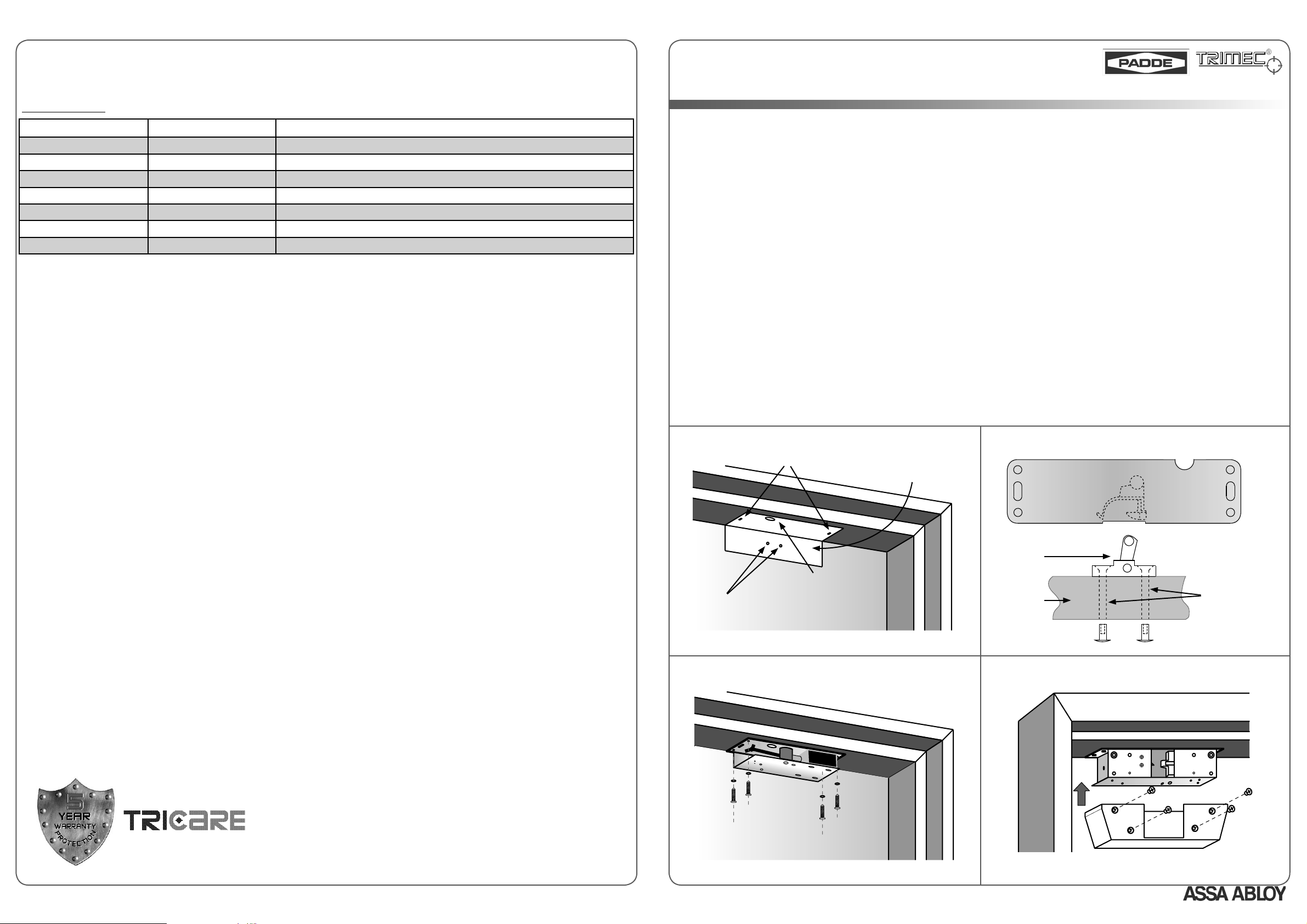
Surface Mount Installation
1.
Remove cover screws and cover from hook lock.
2.
Use cardboard template supplied to mark the position of two elongated lock mounting holes in the door frame, wiring access hole and
two mounting holes for the striker on the door (see Fig. 1). The lock should not be fi tted within 20mm of any corner.
3.
Using the wiring diagram provided on lock body or the datasheet, ensure all wiring is correctly connected and not rubbing on sharp edges
or interfering with any lock mechanism.
4.
Using ONLY the two elongated holes in the lock body, fi x hook lock to door frame using the 6G self-tapping screws and washers provided.
Ensure that lock hook is facing the door.
5.
Fix striker to door as per orientation shown in Fig. 2. Use
doors.
6.
Allow the door closer to latch the lock by fi rst holding the door with the striker resting on the lock hook, and then releasing it. Adjust the
lock position until striker engages hook lock repeatedly without assistance.
7.
Check that hook lock functions with power supplied. Lock should still latch freely under minimum closer force.
8.
Mark and drill the remaining four fi xing holes for the lock before securing the lock in its permanent position (see Fig. 3).
9.
Fit cover to lock body, then recheck that door opens and closes smoothly (see Fig. 4). Ensure that wiring is not trapped or pinched by
cover.
ø9mm mounting holes for wooden doors; ø11mm mounting holes for metal
5 Year Limited Warranty
ASSA ABLOY Australia guarantees for a period of 5 years in accordance with Trimec’s Standard Warranty Conditions, against defects in
manufacture, workmanship or materials, provided that all electrical and mechanical installation requirements are adhered to as per this
datasheet. All third party and consequential claims are expressly excluded from this warranty.
Fig. 1 - Mark Mounting and Wiring Holes with Template Provided
Lock Mounting Holes
Template
Wiring Access Hole
Striker Mounting Holes
Fig. 3 - Drill Fixing Holes, Secure Lock in Permanent Position
Fig. 2 - Fit Striker to Door in Orientation Shown
Roller
Striker
Door
Fig. 4 - Fit Cover to Lock
TRIMEC
TRIMEC
Drill ø9mm in
WOODEN door
OR
ø11mm in
Drill
METAL door
ASSA ABLOY Australia
warranty
2/16 Atkinson Road
Taren Point 2229
NSW, Australia
www.trimec.com.au
DA0095, Issue 2: 27th Feb 2007
age
An ASSA ABLOY Group brand
Page
Page 2
2
3
Mortise Installation
1.
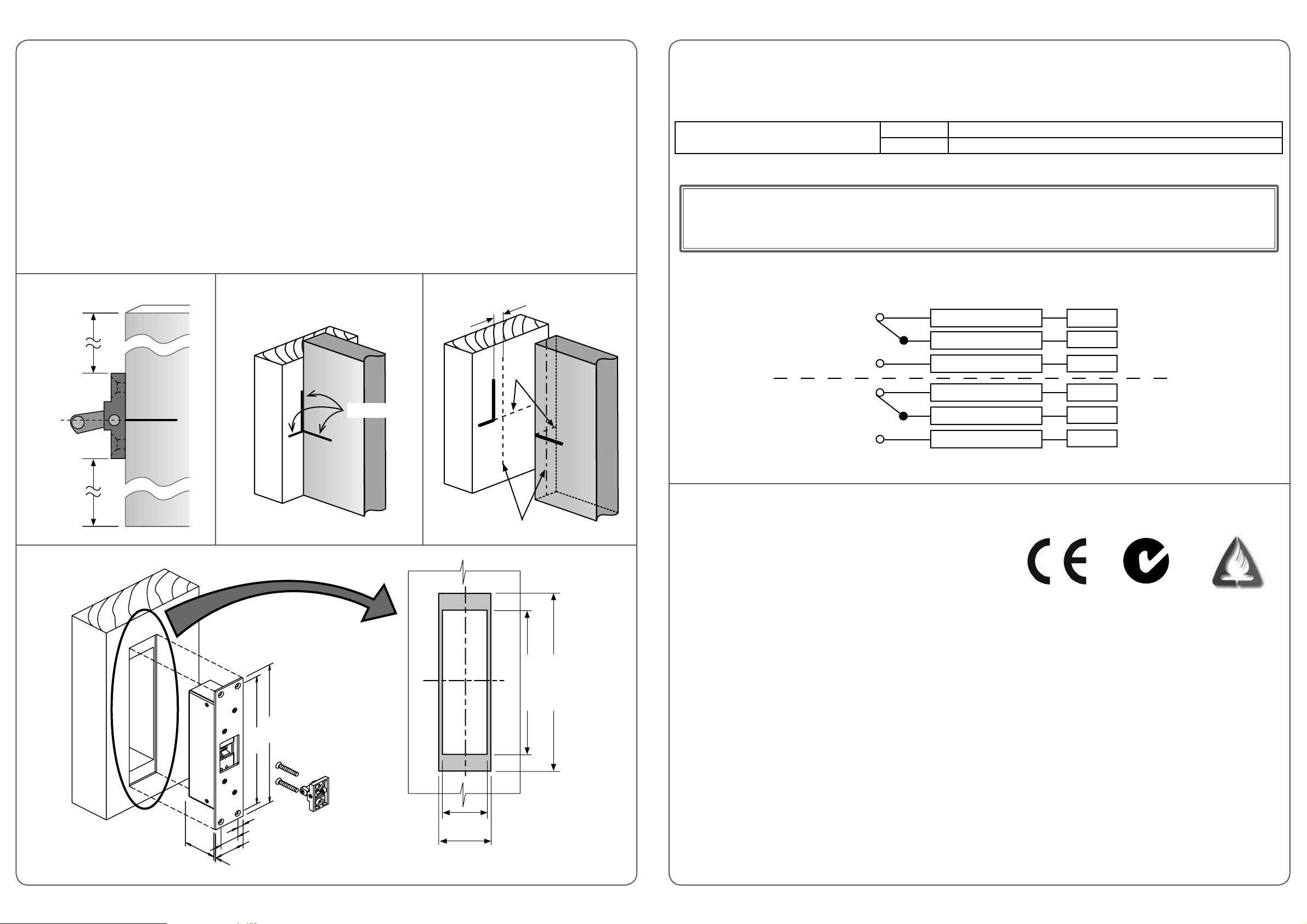
Place roller striker at a desired position along the edge of the door. Measure half the height of the roller striker and mark a horizontal line
(A) on the side of the door (see Fig. 5). Note that the striker must NOT be placed within 150mm from the top or bottom of the door.
2.
Remove striker, then close door and transfer horizontal line (A) to the door frame. Also, mark a vertical line on door frame
corresponding to one face of the door (see Fig. 6).
3.
Open door, then mark on both the door and frame 2 lines (B) that are parallel to the vertical line, at a distance equal to half the thickness
of the door (see Fig. 7).
4.
Extend lines A and B on the door and frame until they intersect. The 2 lines on the door frame are the centrelines of the cutout.
5.
Measure and mark the cutout onto the door frame, then route out opening (see Fig. 8).
6.
Using the wiring diagram provided on lock body or the datasheet, ensure all wiring is correctly connected and not rubbing on sharp edges.
7.
Install hook lock into door frame cavity and secure with mounting screws provided.
8.
Mortise roller striker into door if necessary, using the striker body as template. Secure striker to door, ensuring that the striker fi xing holes
are in line with the marked vertical centreline, and in the orientation as per Fig. 2.
9.
Gently close door to check for correct alignment of striker when it engages the lock. A maximum of 1mm “door rattle” should be allowed.
10.
Open and close door repeatedly to check for correct operation of all functions.
Fig. 5 - Mark Horizontal Line on Door
TOP
≥ 150mm
Fig. 6 - Transfer Lines to Door Frame
Fig. 7 - Mark Parallel Lines
1/2 Door Thickness
Extend
A
ELECTRICAL SPECIFICATIONS
Solenoid Leads Colour
Red
Black
Current Draw
Circuit Protection : Reverse Polarity and Back EMF protection. Solenoid is continuously rated.
@ 12 VDC Initially 830 mA reducing to 250 mA after 1 second
@ 24 VDC Initially 530 mA reducing to 140 mA after 1 second
CAUTION! Incorrect supply voltage may cause damage not covered by warranty. Please check supply voltage with a suitable meter
to ensure it is within 12-30 VDC.
This product has been designed for use in weather protected areas only. DO NOT OIL OR LUBRICATE.
6000 Series Microswitch Monitoring
The 6000 Series hook lock is fi tted with a UL approved changeover microswitch (max. rating: 125 VAC, 3 A / 60 VDC, 200 mA) to monitor
the lock and door status. The wiring diagram for the monitoring schematic is shown in Fig. 9 and on the back of the strike.
N.C. (Normally Closed)
Lock Monitor
Common
N.O. (Normally Open)
Supply Voltage
12-30 VDC
Ground (0 V)
White
Orange
Grey
A
Door
≥ 150mm
BOTTOM
Fig. 8 - Mark Cutout and Route Opening
Door Frame
258.5
238.5
A
Mark Lines
Door Frame
Extend B
211
259
N.C. (Normally Closed)
Door Monitor
N.O. (Normally Open)
Fig. 9 - Monitoring Schematic
Certifi cation
AS4145.2 compliant
•
BS5872 approved
•
CE compliant
•
up to 4-hours fi re rating, depending on type of doorset
•
(in accordance with AS1905.1 - 1997, Part 1: Fire-resistant Doorsets)
Performance
Standard UL 1034 Tested for:
1,500 lbs. (680 kg) static strength rating
•
70 foot-lbs. dynamic strength rating
•
250,000 cycles endurance rating
•
Common
Yellow
Violet
Brown
4
Hour
At the request of ASSA ABLOY Australia, this model was tested to the following VOLUNTARY ratings:
2,000,000 cycles of operation
•
660 lbs. (300 kg) pre-load capability
•
10
32
52
54.5
3.0
age
46
52
Cutout Dimensions
age
 Loading...