

Page 1
4
100A/110A SERIES SPARE PARTS & ACCESSORIES
100A/110A SERIES ELECTRIC STRIKE
The following are available as optional extras:
SPARE PARTS
Part Number Qty Per Pack Description
220100-501 1 12 V Solenoid Coil
220100-512 1 12 V Weather Resistant Solenoid Coil
220100-502 1 24 V Weather Coil
220100-511 1 24 V Weather Resistant Solenoid Coil
220100-509 1 48 V Solenoid Coil
200100-100 5 100 Series Locking Pins, Spring and Stop Screw
200100-110 5 100 Series Weather Resistant Locking Pins, Spring and Stop Screw
200110-100 5 110 Series Locking Pins, Spring and Stop Screw
200110-110 5 110 Series Weather Resistant Locking Pins, Spring and Stop Screw
ACCESSORIES
Part Number Qty Per Pack Description
220100-506 1 100 Series 15mm Extension Lip *
220110-502 1 110 Series 15mm Extension Lip *
220100-507 1 100 Series 25mm Extension Lip *
220110-503 1 110 Series 25mm Extension Lip *
220100-508 1 100 Series 50mm Extension Lip *
220100-504 1 110 Series 50mm Extension Lip *
* When the use of extension lips is required, the standard model numbers of electric strikes must be suffi xed with “X” to denote
pre-drilled extension holes (e.g. 110X).
INSTALLATION INSTRUCTIONS
DRAWINGS NOT TO SCALE. INFORMATION IN THIS DATASHEET MAY BE CHANGED WITHOUT NOTICE.
IMPORTANT NOTE: Ensure any rebate strips or door stops are fi tted before proceeding.
For double-leaf doors, the inactive leaf must be securely fi xed in the closed position and a rebate strip fi tted to prevent
door over-travel.
100 Series strike suitable for 15mm latches, based on a 3mm door gap.
110 Series strike suitable for 18mm latches, based on a 3mm door gap.
1.
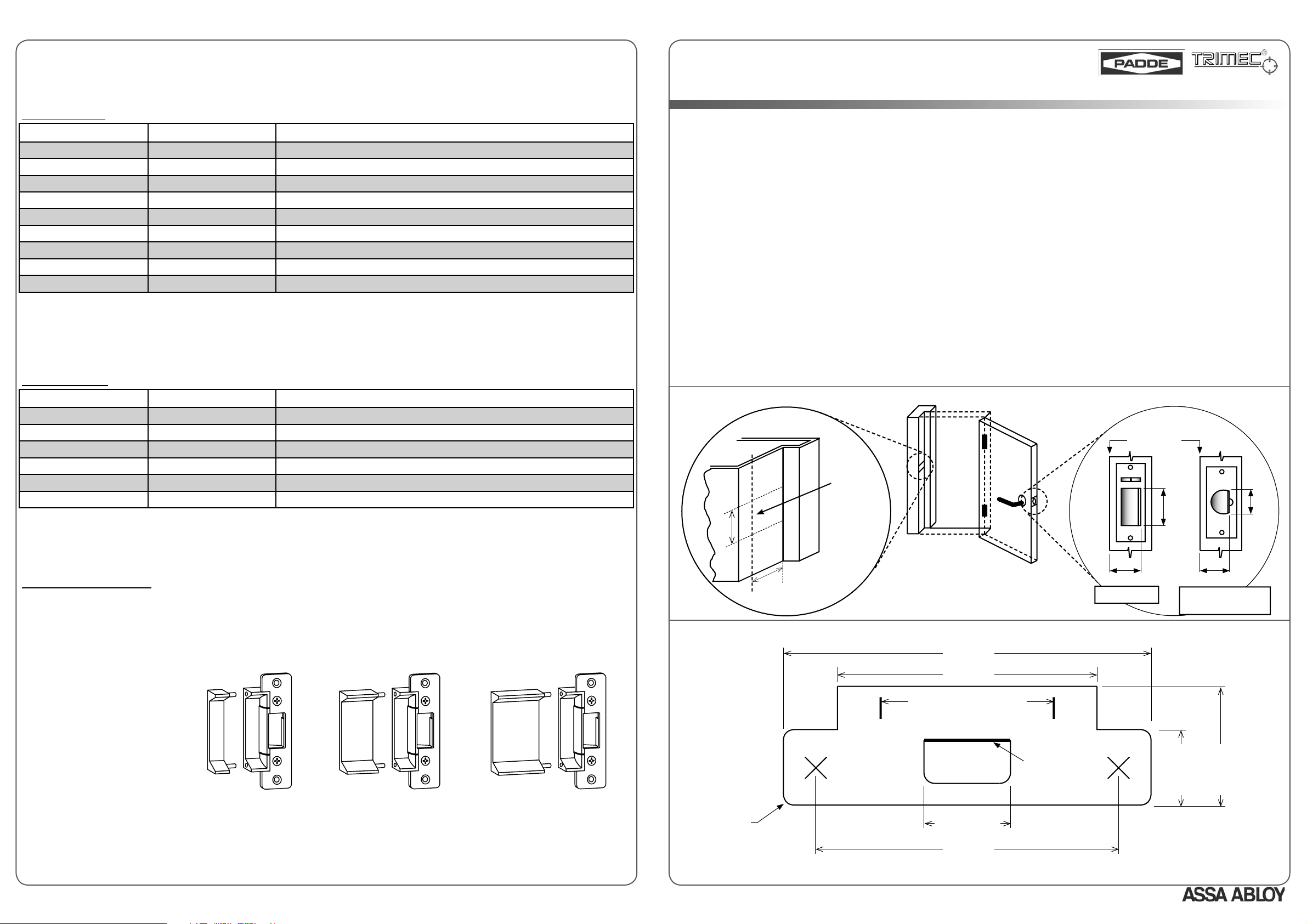
Mark positions X and Y of door latchbolt on door jamb (see Fig. 1).
2.
Remove the backing of supplied stick-on template, and apply to door jamb. Ensure the lines “Front face of Lock Latch” on both template
and door jamb are aligned (see Note 1).
3.
Scribe the door jamb according to template outline (see Fig. 2).
4.
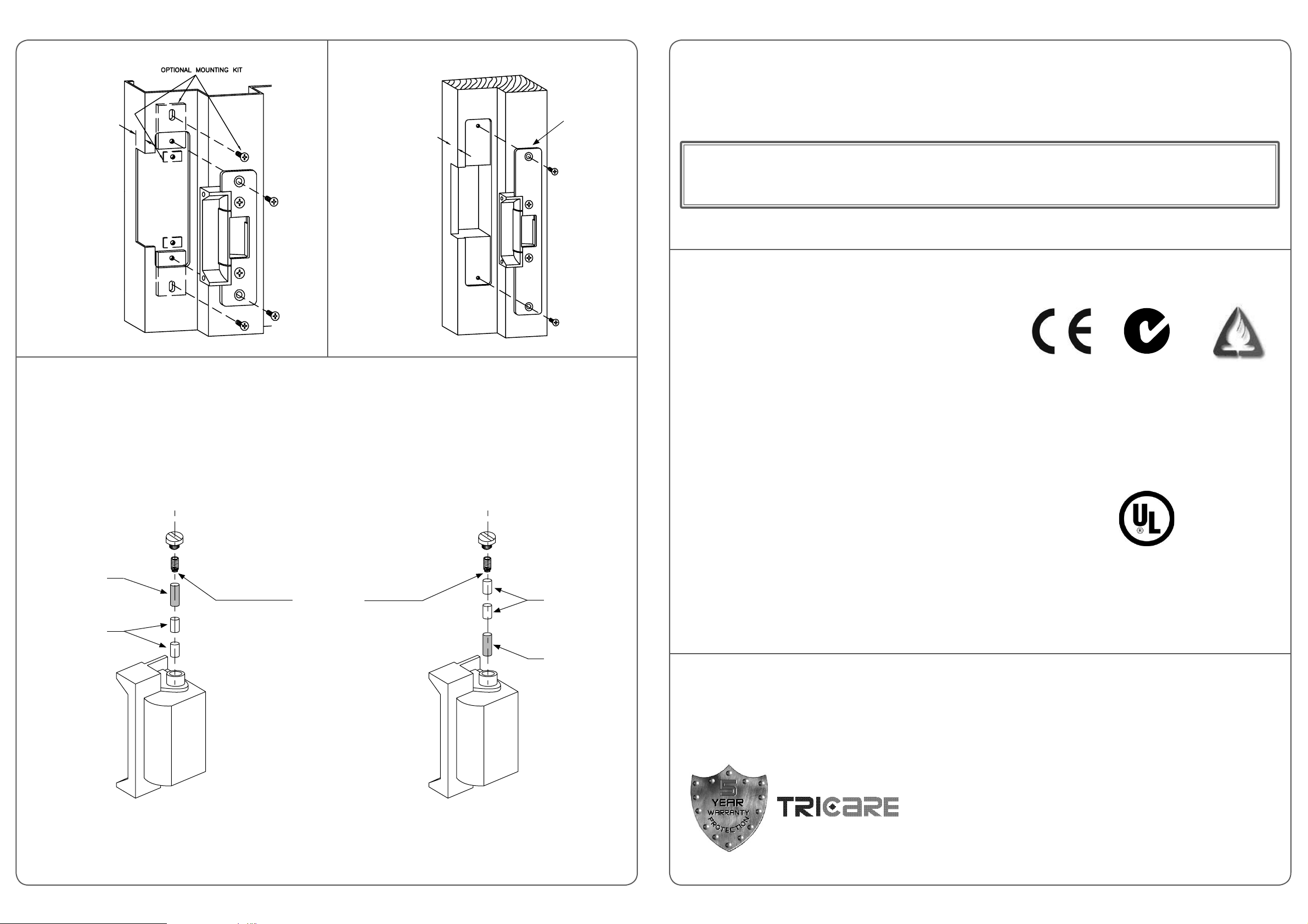
Prepare door jamb as per appropriate installation type; for Metal Jamb refer to Fig. 3, for Wood Jamb refer to Fig. 4. Install mounting tabs
where applicable. (see Note 2).
5.
Ensure all wiring is correctly connected and not rubbing on sharp edges or interfering with any strike mechanism.
6.
Install the strike temporarily in position and check there is no interference between the door, strike and lock face plates, and the extension
lip of strike during door closing. Ensure the deadlatching auxiliary bolt does not enter the strike keeper area when door is closed.
7.
Check there is no pressure on the strike keeper when door is closed.
8.
When all above checks are complete, secure strike with appropriate screws and re-check operation.
NOTE 1 : A 1mm clearance has been designed into the template to prevent the door exerting pressure on the strike when closed.
NOTE 2 : Allow suffi cient space between the electric strike unit and jamb cut-out for the wires. Bunching of wires may cause the unit
to malfunction.
Fig. 1 - Door Frame Preparation
Bevelled Face
Door Edge
Align with
“Front Face
of Lock
Latch” line
on Template
y
y
y
or
or
y
y
STRIKE FACE PLATES
For a wide range of strike face plates to suit a particular application, please contact your nearest distributor.
A
B
C
15mm extension lip (A),
25mm extension lip (B)
15mm
25mm
50mm
50mm extension lip (C)
available as optional extras.
DA0006, Issue 8: 16th Feb 2007
age
x
Fig. 2 - 100A/110A Series ANSI Face Plate Type “A” Template Outline
*123.7mm
*86mm
Limits of Extension Lips
59.5mm
NOT TO SCALE
R 4.0mm
*These dimensions have a tolerance of +0.8mm/-0
Template outline may vary depending on strike face plate used.
An ASSA ABLOY Group brand
Keeper Width
38.8mm
104.8mm
age 1
Front Face of
Lock Latch
X
xx
Mortice Lock
31.7mm
X
Tubular/Cylindrical
Latch
*43.7mm
Page 2
2
3
Fig. 3 - Metal Jamb Installation
Fig. 4 - Wood Jamb Installation
ELECTRICAL SPECIFICATIONS
100A series - 17mm
110A series - 20mm
100B series - 17mm
110B series - 20mm
“B” Plate
strike shown
CHANGING MODE OF LOCK OPERATION
1.
To change electric strike’s mode of lock operation, remove brass screw from top of strike body.
2.
Invert strike and release the spring and 3 locking pins (2 x Short pin, 1 x Long pin).
3.
Re-insert pins in in the manner shown for the desired mode of lock operation (Power to Open: see Fig. 5; Power to Lock: see Fig. 6),
followed by the spring.
4.
Screw in the brass screw to strike body. This will secure the spring and locking pins
Solenoid Leads Colour
Red
Blue
Supply Voltage
12 VDC
24 VDC
Current Draw
250 mA
187 mA
CAUTION! Incorrect supply voltage may cause damage not covered by warranty. Please check supply voltage with a suitable meter
to ensure it is within +/- 15% of the nominal voltage shown above with the strike powered.
This product has been designed for use in weather protected areas only. DO NOT OIL OR LUBRICATE.
Certifi cation
AS4145.2 compliant
•
BS5872 approved
•
CE compliant
•
up to 20-minutes fi re rating, depending on type of doorset
•
(in accordance with AS1905.1 - 1997, Part 1: Fire-resistant Doorsets)
20
Mins
UL Listing
Wiring methods and materials shall be in accordance with the National Electric Code, ANSI/NFPA 70 - 1996.
•
Unit must be powered by a UL listed limited energy power source.
•
Use only those mounting screws and hardware supplied with the product for installation. Do not use substitute installation fasteners or
•
hardware.
UL listed for burglary resistance category 1034.
•
Long Pin
Short Pins
Fig. 5 -
Power to Open (Fail-Secure) Confi guration
Small End of
Spring
Short Pins
Long Pin
Fig. 6 -
Power to Lock (Fail-Safe) Confi guration
Standard UL 1034 Tested and Listed for:
1,500 lbs. (680 kg) static strength rating
•
70 foot-lbs. dynamic strength rating
•
250,000 cycles endurance rating
•
At the request of ASSA ABLOY Australia, this model was tested to the following VOLUNTARY ratings:
1,000,000 cycles of operation
•
5 Year Limited Warranty
ASSA ABLOY Australia guarantees for a period of 5 years in accordance with Trimec’s Standard Warranty Conditions, against defects in
manufacture, workmanship or materials, provided that all electrical and mechanical installation requirements are adhered to as per this
datasheet. All third party and consequential claims are expressly excluded from this warranty.
warranty
www.assaabloyasiapacifi c.com
ASSA ABLOY Australia
2/16 Atkinson Road
Taren Point 2229
NSW, Australia
age
age
 Loading...