

Page 1
EL110 SERIES CABINET LOCK
INSTALLATION INSTRUCTIONS
DRAWINGS NOT TO SCALE. INFORMATION IN THIS DATASHEET MAY BE CHANGED WITHOUT NOTICE.
IMPORTANT NOTE: Lock is designed to be fi tted into cabinets and lockers etc with swing or sliding doors.
Lock is supplied in “Power-to-Open” confi guration as the initial factory setting.
1.
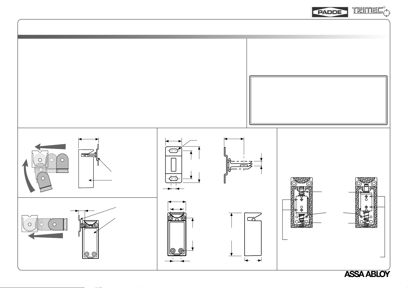
Striker may engage with lock from side or front.
Front Enagement : see Fig.1
Side Engagement : see Fig.2
2.
Mount lock on inside of cabinet, connect wiring (see Electrical Specifi cation) and power up lock. Lock and striker
dimensions are shown in Fig.3. Allow suffi cient space betwen lock unit and cut-out for wires as bunching of wires
may cause unit to malfunction.
3.
Adjust the striker horizontally and vertically to ensure the striker locking recess engages with locking pin in the
lock.
4.
Open and close the door several times, and readjust striker if necessary to achieve a smooth closing operation.
5.
Confi gure lock mode of operation (see Fig.4). Lock may need to be removed temporarily to be reconfi gured.
6.
When lock and striker is in place, remove fi lm from double-sided tape on solenoid and affi x faceplate onto lock.
Fig. 1 - Front Engagement
Fig. 2 - Side Engagement
11
37
To prevent over- or
under-travel, set
distance between
back mounting face
of lock and striker
to 37mm.
Striker
Lock
Striker
Lock
To prevent over- or
under-travel, set
distance between
back mounting face of
striker and centre of
nearest fi xing hole of
lock to 11mm.
Fig. 3 - Lock and Strike Dimensions
18
30
21.5
R4
31
39.9
4.5mm Horizontal
Adjustment
55
13.5
22.5
ELECTRICAL SPECIFICATIONS
Solenoid Leads Colour
CAUTION! Incorrect supply voltage may cause damage not cov-
ered by warranty. Please check supply voltage with a suitable meter
to ensure it is within +/- 15% of the nominal voltage shown above
with the strike powered.
This product has been designed for use in weather protected areas
only. DO NOT OIL OR LUBRICATE.
5mm Sliding
Vertical Adjustment
72.7
28
Supply Voltage
Red
Blue
Black
Fig. 4 - Changing Mode of Lock Operation
Remove two rear solenoid fi xing screws.
•
Remove solenoid, spring and wire.
•
Confi gure solenoid, spring and wire depending on the
•
lock mode required, as shown below.
Power-to-Lock
(Fail Safe)
For Power-to-Lock (Fail Safe), reinsert using the
two lower solenoid fi xing screw holes.
For Power-to-Open (Fail Secure), reinsert using
the two upper solenoid fi xing screw holes.
12 VDC
24 VDC
48 VDC
Power-to-Open
Short Spring
Wire
Long Spring
Current Draw
175 mA
88 mA
45 mA
(Fail Secure)
An ASSA ABLOY Group brand
Page 2

5 Year Limited Warranty
ASSA ABLOY Australia guarantees for a period of 5 years in accordance with Trimec’s Standard Warranty Conditions, against defects in manufacture, workmanship or materials, provided that all
electrical and mechanical installation requirements are adhered to as per this datasheet. All third party and consequential claims are expressly excluded from this warranty.
warranty
ASSA ABLOY Australia
2/16 Atkinson Road
Taren Point 2229
NSW, Australia
www.assaabloyasiapacifi c.com
DA0015, Issue 4: 2nd Apr 2007
 Loading...