

Trimble Navigation PDLUH05 Users manual

PDL
User's Guide
Revision 04
December 2004
Pacific Crest Corporation
990 Richard Avenue, Suite 110
Santa Clara, CA 95050
(408) 653-2070
(408) 748-9984 Fax
PN: M0052204

ii iii

NOTICE
PACIFIC CREST CORPORATION MAKES NO WARRANTY
OF ANY KIND WITH REGARD TO THIS MATERIAL,
INCLUDING, BUT NOT LIMITED TO, THE IMPLIED
WARRANTIES OF MERCHANTABILITY AND FITNESS FOR A
PARTICULAR PURPOSE. Pacific Crest Corporation shall not
be liable for errors contained herein or for incidental
consequential damages in connection with the furnishing,
performance, or use of this material.
This document contains proprietary information that is protected
by copyright. All rights are reserved. No part of this document
may be photocopied, reproduced, or translated into another
language without the prior written consent of Pacific Crest
Corporation.
The information contained in this document is subject to change
without notice.
CAUTIONS AND WARNINGS
Throughout this manual this symbol is used to indicate
9
caution or warning. Please pay particular attention to
these items to assure safe and reliable operation of
your radio modem product.

iv
© Copyright 2004 Pacific Crest Corporation. All rights reserved.
Reproduction, adaptation, or translation of this manual is
prohibited without prior written permission of Pacific Crest
Corporation, except as allowed under the copyright laws.
Trimtalk and Trimble are trademarks of Trimble Navigation Ltd.

v
TABLE OF CONTENTS
Notice........................................................................................... iii
Cautions and Warnings ...............................................................iii
Table of Contents ........................................................................ v
Introduction .................................................................................. 1
Welcome .................................................................................. 1
Scope ....................................................................................... 1
Note Concerning this Guide..................................................... 1
Features and Benefits.................................................................. 3
Setting Up The PDL High Power Base........................................ 5
Overview of PDL High Power Base Radio Modem.................. 5
PDL High Power Base System Setup...................................... 9
Setting Up The PDL Low Power Base/Repeater....................... 15
Overview of PDL Low Power Base Radio Modem ................ 15
PDL Low Power Base Setup.................................................. 18
Setting Up The PDL Rover ........................................................ 21
Overview of PDL Rover Radio Modem.................................. 21
PDL Rover Setup ................................................................... 24
Tips and Techniques for Best Performance .............................. 28
Antenna.................................................................................. 28
Power Supplies ...................................................................... 28
How to Use AutoRover™....................................................... 28
How to Use AutoBase™ ........................................................ 29
Equipment Care ..................................................................... 30
Error Codes............................................................................ 30
FCC Rules and Regulations ...................................................... 33
Licensing Requirements ........................................................ 33
Equipment Compliances ........................................................ 33
Being Part of the RF community ............................................ 34
Automatic Station Identification.............................................. 35

vi
Carrier Sense Multiple Access (CSMA)................................. 35
Service and Support .................................................................. 37
Contacting Pacific Crest Corporation..................................... 37
Warranty .................................................................................... 39
Two-year Limited Warranty.................................................... 39
Exclusions .............................................................................. 39
Warranty Limitations .............................................................. 39
Appendix A - Pin-outs and Connectors ..................................... 43
PDL Base ............................................................................... 43
PDL Rover.............................................................................. 43
Antenna.................................................................................. 43
Appendix B - Technical Specifications ...................................... 45
General .................................................................................. 45
Radio...................................................................................... 45
Modem ................................................................................... 46
Environmental ........................................................................ 47
Table of Figures
Figure 1 - PDL High Power Base Front Panel............................. 5
Figure 2 - PDL High Power Base Rear Panel ............................. 8
Figure 3 - PDL High Power Base System Setup....................... 10
Figure 4 - PDL Low Power Base .........................................…...16
Figure 5 - PDL Low Power Base Setup….……………………….19
Figure 6 - PDL Rover……………………………………………….22
Figure 7 - PDL Rover Setup ……………………………………….25
Figure 8 - PDL Data/Power Connectors…………………..……...41

INTRODUCTION
Welcome
Thank you for purchasing the Positioning Data Link™ (PDL™)
for use with your survey system. The PDL is an advanced, high
speed, wireless data link that is designed specifically for
GPS/RTK applications. Your success in using the PDL is our
primary goal. We stand behind our product with expert support
and service. We welcome your comments and questions.
Scope
This guide introduces the PDL Base and rover radio link systems
used for GPS and RTK applications. It is written for the first-time
user, and gives details concerning system setup, operation and
maintenance. We urge you to take the time to review this short
manual completely prior to setting up your system.
Note Concerning this Guide
We believe that the PDL system provides the best value and
performance for the user. As such, we provide our equipment in
complete turnkey systems, including all of the items necessary
for operation with your GPS.
You may have purchased your PDL from a third party. On
occasion, the bundled product provided by these sources may
differ from the kits provided directly from Pacific Crest
Corporation. If this guide does not accurately reflect the
equipment that you received, please contact your supplier for
specific instructions concerning the setup of items that differ.

2 Introduction
This page intentionally left blank.

FEATURES AND BENEFITS
Fast Over-the-Air Data Rate – 19,200 bits per second
• Reduced latency provides better GPS position information
• Lower power consumption allows longer field operation
• Greater throughput handles both GPS and GLONASS
Enhanced User Interface – Channel display and buttons
• View and change radio channel
• Monitor charge status and other parameters
Intelligent Protocols – Forward Error Correction (FEC),
AutoBase™ and AutoRover™ technology
1
• FEC provides improved noise immunity and range
• Base automatically selects channel with AutoBase
• Rover automatically locks to base with AutoRover
Rugged Construction – Designed specifically for GPS RTK field
surveying
• Double shock mounted electronics improve reliability
• Water tight operation stands up to bad weather conditions
• Built-in mounts simplify tripod and range pole mounting
Backward Compatible – Interoperable with RDDR, RFM and
Trimble® products
• Benefit by the latest technology with your existing equipment
• Facilitates GPS equipment mix and match
• Provides upgrade path for existing installations
1
Patents Pending

4 Features and Benefits
This page intentionally left blank.

SETTING UP THE PDL HIGH POWER BASE
Overview of PDL High Power Base (PDL HPB) Radio Modem
Front Panel
Digital Display
Channel Change Pushbutton
TX Indicator
RX Indicator
ON / OFF Indicator
ON / OFF Pushbutton
AMP POWER
Indicator
Figure 1 - PDL High Power Base Front Panel
Buttons
The ON/OFF button is used to turn the PDL HPB station on and
off. Turn the unit on by pressing the ON/OFF button and holding
it until the channel display indicator is lit. Turn off the PDL HPB
by pressing the ON/OFF button until the display goes blank.
There is a one-second turn-off delay in the power button to
prevent inadvertent turn off.

6 Setting Up the PDL High Power Base
The CHANNEL button is used to display and change the
channel. Press the CHANNEL button momentarily to display the
selected channel. To change the channel, press the CHANNEL
button once to light the display, and then again to change the
channel.
Use the CHANNEL button to select the “b” setting. With “b”
selected, the PDL HPB will be placed in AutoBase mode. This
mode selects the channel for transmission automatically.
Display
The seven-segment numeric display is used to indicate the
channel or mode selection. To conserve power, the display is
only lit for a short time following the pressing of the CHANNEL or
ON/OFF buttons. Channel selections range from Channel 0 to
Channel 15. Two digit channel numbers are displayed by
alternately flashing a 1 followed by the second digit.
The seven-segment display also has a decimal point to the lower
right of the number. The decimal point is lit to indicate that the
channel selection was done automatically with AutoRover or
AutoBase.
Indicator LEDs
The power LED has two purposes – first, to indicate that the unit
is powered, and second, to indicate the level of charge for the
power supply. The power LED will blink to indicate that the
base station battery is at or below 10 Volts and may require
charging.

PDL User's Guide 7
The amplifier power LED indicates the RF power output level
selected. When lit, the amplifier power LED indicates that the
RF output power is set to high. When blank, the amplifier power
LED indicates that the RF output power is set to low.
The TX LED indicates that the PDL HPB is actively transmitting.
In most RTK applications, the base station TX LED will blink
once per second.
The RX LED indicates that the PDL HPB is receiving an RF
carrier signal. If the RX LED is lit for extended periods of time, or
continuously, then another radio station is operating on the same
frequency. This competing RF source may interfere with the
GPS RTK system, and may require that you change channels for
better performance.
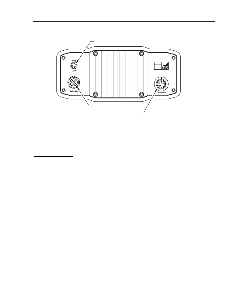
Rear Panel
Data Connector
A five-pin circular LEMO style receptacle accepts both
programming and GPS model specific cables. The supplied
cables are labeled “RADIO” on the end that plugs into the base.
Align the red dot on the plug with the red dot on the receptacle
and push until a clicking sound is heard.
To remove the cable, grasp the blue cable over-mold, and retract
the locking mechanism by pulling the knurled barrel of the plug
toward your palm.
8 Setting Up the PDL High Power Base
r
Amp Power Selector Switch
CAUTION
HOT
SURFACE
Antenna Connector
Data / Power Connecto
Figure 2 - PDL High Power Base Rear Panel
RF Connector
A BNC jack accepts the BNC male plug coming from the
antenna mount.
Enclosure
The PDL HPB enclosure is rugged extruded aluminum with
integrated heat sink fins. The enclosure is painted with a
weather resistant powder coat blue paint. Black bumpers are
integrated with front and rear gaskets to provide shock protection
and watertight operation. The enclosure is not designed to
withstand submersion and must not be allowed to sit in standing
water.

PDL User's Guide 9
Warning: The PDL HPB enclosure and heat sink may
9
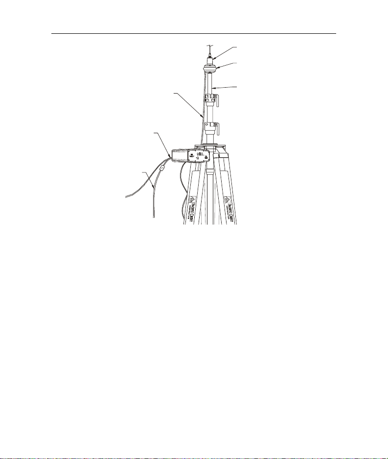
PDL High Power Base System Setup
Antenna and Antenna Mount
Begin your PDL HPB station set up by screwing the Antenna
Mount to the top of the Tripod Antenna Mast. You may want to
leave the mount permanently attached to the mast and avoid this
step in the future.
Next, screw the Antenna on the Antenna Mount. We
recommend inspecting the antenna center push-pin contact to
ensure that it makes good contact with the antenna mount. A
good antenna connection is critical to system performance.
Tripod Antenna Mast
With the Antenna Mount and Antenna connected, extend the
legs of the Tripod Antenna Mast and set up the tripod on level
ground. Spread the tripod legs sufficiently to provide a stable
base.
become very hot during operation. This is normal
depending on the ambient temperature, RF power
selection and transmission duty cycle. Turn off the unit
and allow it to cool prior to handling.
10 Setting Up the PDL High Power Base
A
A
ntenna
ntenna Mount
Antenna Cable
Data / Power Cable
Battery Cable
To GPS Unit
To B at ter y
Tripod M ast
Figure 3 - PDL High Power Base System Setup
Caution: Do not extend the antenna mast in conditions
9
of high wind or in situations where the uneven terrain or
other soil conditions provide an unstable base. Keep
the area surrounding the Tripod Antenna Mast clear
and exercise caution to prevent injury or damage to
property should the Tripod Antenna Mast fall.
Connecting the PDL HPB
The PDL HPB has a built-in tripod mounting bracket that allows
easy mounting to the tripod. Locate the mounting flange at the
top portion of one of the Tripod legs, and hook the PDL HPB in
place.
 Loading...