


PDL Base
Radio Modem
User's Guide
i
Revision 0.2 (preliminary)
May 1999
Copyright 1999 Pacific Crest Corporation
Document M00522
Pacific Crest Corporation
990 Richard Avenue, Suite 110
Santa Clara, CA 95050
(408) 653-2070
(408) 748-9984 Fax
sales@paccrst.com
http://www.paccrst.com

Contents
Contents.............................................................................................................ii
Getting Acquainted .............................................................................................1
Introduction..................................................................................................1
Main Components........................................................................................2
Compliance..................................................................................................6
Electrical Considerations....................................................................................8
Power Supply...............................................................................................8
Data Interface ..............................................................................................8
Appendix A - Cables and Connectors .................................................................9
Data/Power Connector................................................................................. 9
Appendix B - Technical Specifications ..............................................................10
General...................................................................................................... 10
Radio Transceiver...................................................................................... 10
Modem....................................................................................................... 11
Environmental............................................................................................11
ii

Pacific Crest Corporation – PDL Base User’s Guide 1
Getting Acquainted
Introduction
Radio modems provide wireless data communication between remote systems in
situations where wireline communication is difficult or impossible. For field
operations such as remote monitoring and control, DGPS, and data telemetry,
the radio modem provides the ideal link between remote computers, instruments
and other RS-232 devices.
The PDL Base is a high-speed, radio modem designed for field, mobile or office
operation. At the heart of the PDL is a high quality, multi-channel telemetry radio
engineered specifically for data communications. Using a simple 3-wire RS-232
interface, the PDL can easily be connected to most computers and instruments to
provide an efficient and reliable data link.
To meet the needs of a variety of applications, the PDL can be configured with an
IBM-PC compatible computer. Operating parameters such as data transmission
rate, mode, and others can be configured quickly without having to modify the
modem hardware.
Pacific Crest Corporation stands behind its products by providing comprehensive
customer support with quick and efficient service. We understand that your
success in using our products is key. For this reason, our toll-free number is
available for sales and service questions (U.S. and Canada). Additional
customer service options are available to assure that your radio modem products
are properly maintained, and to assure minimum downtime should a problem
occur.
Monday through Friday - 8:00 a.m. to 5:00 p.m. (PST)
1-800-795-1001 (Toll-free U.S. and Canada)
(408) 653-2070 (International/Local)
(408) 748-9984 (Fax)
sales@paccrst.com (Internet)
http://www.paccrst.com
Pacific Crest Corporation – PDL Base User’s Guide2
Main Components
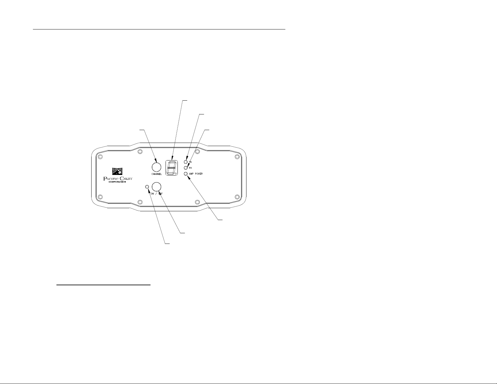
This section will acquaint you with the physical attributes of the PDL Base radio
modem. Figures 1 and 2 show the standard PDL Base unit.
Digital Display
TX Indicator
Channel Change Pushbutton
RX Indicator
PDL
Positioning
Data Link
AMP POWER Indicator
ON / OFF Pushbutton
ON / OFF Indicator
Figure 1 – PDL Base: Front View
PDL Base Front Panel Features
ON / OFF Pushbutton – An environmentally sealed pushbutton switch used for
turning the unit on and off.
ON / OFF Indicator – An LED indicator used to show the unit is powered up.
Channel Change Pushbutton – An environmentally sealed pushbutton switch
used to select among the preprogrammed channels.

Pacific Crest Corporation – PDL Base User’s Guide 3
Digital Display – A seven-segment LED used to indicate channel status and
other diagnostic information.
TX Indicator – An LED indicator which will light when the unit is transmitting
data.
RX Indicator – An LED indicator which will light when the unit is receiving data.
AMP POWER Indicator – An LED indicator which shows the selected RF output
level. The desired level is selected with the Amp Power Selector Switch located
on the back panel. The LED is off when the “LO” (2 Watt) position is selected,
and on when the “HI” (35 Watt) position is selected.

Pacific Crest Corporation – PDL Base User’s Guide4
Amp Power Selector Switch
Antenna Connector
RS-232 / Power Connector
Figure 2 – PDL Base: Back View
PDL Base Back Panel Features
Amp Power Selector Switch – An environmentally sealed toggle switch used for
selecting the desired RF output level. The output power is 2 Watts when the
switch is in the “LO” position, and 35 Watts when in the “HI” position.
Antenna Connector – An environmentally sealed panel mount 50 Ohm female
BNC connector for external antenna connection.
RS-232 / Power Connector – An environmentally sealed panel mount LEMO #1
shell receptacle which contains contacts for a three-wire RS-232 serial bus and
input power connections. The following signals are available on the connector:
RS-232 / Power Connector – continued

Pacific Crest Corporation – PDL Base User’s Guide 5
• Pin 1 -- Power
• Pin 2 -- Ground
• Pin 3 -- TX Data
• Pin 4 -- Signal Ground
• Pin 5 -- RX Data
1
2
3
Figure 3 – PDL Base: RS-232 / Power Connector
5
4
Compliance

Pacific Crest Corporation – PDL Base User’s Guide6
The PDL BASE is designed to be compliant with many worldwide regulatory
requirements, including FCC CFR Title 47 Part 90 and Part 15. Changes or
modifications not expressly approved by Pacific Crest Corporation could possibly
void the user’s authority to operate this equipment.
Note: this equipment has been tested and found to comply with the limits for a
class A digital device, pursuant to part 15 of the FCC Rules. These limits are
designed to provide reasonable protection against harmful interference when the
equipment is operated in a commercial environment. This equipment generates,
uses, and can radiate radio frequency energy and, if not installed and used in
accordance with the instruction manual, may cause harmful interference to radio
communications. Operation of this equipment in a residential area is likely to
cause harmful interference in which case the user will be required to correct the
interference at his own expense.
Part 15 Compliance (for U.S.)
The PDL Base complies with Part 15 of Title 47 of the Code of Federal
Regulations. Operation is subject to the condition that this device does not cause
harmful interference.
Part 90 Compliance (for U.S.)
The PDL Base is type accepted for operation under the rules and regulations of
Parts 2 and 90 of Title 47 the Code of Federal Regulations. Refer to the label
affixed to the unit for the FCC ID designator and other designators for
international compliance.
Licensing Requirement (for U.S.)
The FCC regulates the use of the radio frequency spectrum. An FCC license of
authorization must be obtained prior to operating the PDL Base radio modem. It
is the responsibility of the user to maintain current knowledge of the rules and
regulations to assure compliance.
Application for a license is made by submitting FCC form 600 along with
evidence of frequency coordination (if required) and applicable fees to the FCC.

Pacific Crest Corporation – PDL Base User’s Guide 7
The FCC vigorously pursues and prosecutes those who operate unlicensed radio
stations. All radio operation must be authorized and licensed by the FCC.
Without the cooperation of the radio user community, the airwaves would soon
become overcrowded, making operations such as data transmission impossible.

8 Pacific Crest Corporation - PDL Base User’s Guide8
Electrical Considerations
Power Supply
The PDL Base has power supply connections on pins 1 and 2 of the RS-232 /
Power connector. Supply voltages greater than 16 Volts will cause the unit to
shut off. Pins 1 and 3 are connections to the power ground and RS-232 interface
signal grounds respectively. Note that these pins are tied to a common point on
the PDL BASE. If there is a potential for a ground path current loop due to
improper power application, we recommend a fusible link be inserted in the signal
ground to protect the PDL BASE.
The input regulators of the PDL BASE are designed to protect the circuit from
damage due to reverse polarity (up to 20V). Transient voltage protection is also
provided for circuit protection against ESD and other voltage transients.
Data Interface
The data port is a simple 3-wire RS-232 electrical interface with signals for
transmitting data to and from the PDL BASE. It also provides a reference ground
for the TX and RX signals.

Pacific Crest Corporation – PDL Base User’s Guide 9
Appendix A - Cables and Connectors
RS-232 / Power Connector
The RS-232 / Power connector is a 5 pin LEMO #1 shell receptacle. Use Pacific
Crest part number A00470 as a standard programming cable.
RF Connector
The RF connector is a 50 Ohm female BNC connector.
Appendix B - Technical Specifications

10 Pacific Crest Corporation - PDL Base User’s Guide
General
Interface
RS-232 compatible interface configurable for 150 to 38,400 baud operation with
one start, 8 data, optional parity, and one stop bit.
Power Supply
Power supplied externally through the RS-232 / Power connector (9 - 16 VDC).
Typical power consumption during TX is 110 Watts and 1.9 Watts during RX.
Radio Transceiver
Frequency Ranges
Contact factory for currently available frequency ranges.
Frequency Control
Synthesized 12.5 kHz resolution, ±2.5 ppm crystal stability standard.
Channel Spacing
Channel spacing 12.5 kHz and 25 kHz.
RF Output Power
2 Watt ±20% (LO power switch setting).
35 Watt ±20% (HI power switch setting).
Receiver
Sensitivity -116 dBm or better (12dB SINAD). Selectivity -70 dB at 25 kHz.
Modem

Pacific Crest Corporation – PDL Base User’s Guide 11
Link Rate and Modulation
19,200 bps and 9600 with 4 level FSK.
9600 bps and 4800 with GMSK.
Transmission Protocols
Transparent, packet switched, fast asynchronous, digipeater, TRIMTALK ™.
Forward Error Correction (FEC) and Detection
Hamming code (12, 8) with data interleaving.
Environmental
Size
6.23" W x 2.77" H x 6.58" L
(15.8 cm W x 7.0 cm H x 16.7 cm L)
Weight
Standard enclosure – 2.96 lbs. (1.34 Kg)
Shock and Vibration
Per IEC 68-2-55.
Temperature Range
-22° to 140° F (-30° to 60° C) Operating
-67° to 185° F (-55° to 85° C) Non-operating
 Loading...