

TRIMBLE EUROPE 111256 User Manual

GETTING STARTED GUIDE
Z-Max®.Net
www.thalesgroup.com/navigation

English
Copyright Notice
Copyright 2003-2006 Thales Navigation. All rights reserved.
Trademarks
All product and brand names mentioned in this publication are
trademarks of their respective holders.
FCC Notice
Z-Max.Net Receiver complies with the li mits for a Cl ass B digital device, pursuant to the Part 15 of the FCC rules when it is
used in Portable Mode. See Note below related to Class B device.
Class B digital devices NOTE: This equipment ha s be en t es ted
and found to comply with the limits for a Class B digita l device,
pursuant to Part 15 of the FCC Rules. These limits are des igned
to provide reasonable protection ag ainst harmful interference in
a residential installation. This equipment generates, uses, and
can radiate radio frequency energy and, i f not installe d and used
in accordance with the instruct ions, may cause ha rmful interfe rence to radio communications. However, there is no guarantee
that interference will not occur in a particular installation. If this
equipment does cause harmful inter ference to radio or television
reception, which can be determined by turning the equipment
off and on, the user is encouraged to try and cor rect the int erference by one or more of the following measures:
- Reorient or locate the receiving antenna.
- Increase the separation between the equipment and receiver.
- Connect the equipment into an outlet on a circuit different
from that to which the receiver is connected.
- Consult the dealer or an experienced radio/TV technician for
help.
When Z-Max.Net is used with an external power supply or connected to an external device using the USB port, it complies
with the limits for a Class A digital device, pursuant to the Par t
15 of the FCC rules. See Note below related to Class A device.
Class A digital devices NOTE: This equipment has been tested
and found to comply with the limits for a Clas s A digital devi ce,
pursuant to Part 15 of the FCC Rules. These limits are des igned
to provide reasonable protection against harmful interference
when the equipment is operated in a commercial environment.
This equipment generates, uses, and can radiat e radio frequency
energy and, if not installed and used in accordance with the instruction manual, may cause harmf ul in ter fere nce to radio co mmunications. Operation of this equipmen t in a reside ntial area is
likely to cause harmful interference in which case the user wi ll
be required to correct the interference at his own expense.
Remark: Any changes or modifications not expressly approved
by Thales Navigation, could void the right for user to operate
the equipment.
RF Safety Exposure To Radio Frequency Energy (SAR)
Radio transmitting devices radiate Radio Frequency (RF) energy during its operation. RF energy can be absorbed into the human body and potentially can cause adverse health effects if
excessive levels are absorbed. The unit of measurement for human exposure to RF energy is "Specific Absorption Rate"
(SAR).
The Federal Communications Commission (FCC), Industrie
Canada (IC), and other agencies around the world have established limits that incorporate a substantial safety margin designed to assure the safety of all persons using this equipment.
In order to certify this unit for sale in the US, Canada and Europe this unit has been tested for RF exposure compliance at a
qualified test laboratory and found to comply with the regulations regarding exposure to RF Ener gy .SAR was measured with
the unit (GSM Module) transmitting at its maximum certified
RF power. Often, however, during normal operation the unit
(GSM Module) will transmit much less than maximum power.
Transmit power is controll ed automatica lly and, in g eneral is r educed as you get closer to a cellular base station. Thi s reduct ion
in transmit power will result in a lower RF e nergy e xposure and
resulting SAR value.
SAR: ANSI/IEEE C95.1 1992
FCC OET Bulletin 65 Supplement C
1999/519/CE
The highest SAR value for this wireless survey system when
worn on the body, as described i n this user guide, is 1.44 W/kg.
No separation from the body is required when the wireless survey system is in operation as the SAR meas urements were taken
with the unit "touching" the surface of the body. The device
main intent use is for handheld operations only.
FCC and CE UHF Safety Statement
The different versions of the UHF T ransmitters are FCC and CE
compliant.
In order to comply with FCC and CE RF exposure safet y guidelines as body-worn, normal use of unit, the following must be
followed:
A distance of AT LEAST 10 feet (3 m) of separation between
the users body and the unit (UHF Transmitter). This distance
has been defined taken into account the FCC and CE Requirements and the worst output power configuration.
Do NOT use the device in a manner such that it is in di rect contact with the body (e.g. on the lap). Suc h us e wi ll l ik ely exceed
FCC RF safety exposure limits. See www.fcc.gov/oet/rfsafety/
for more information on RF exposure safety.
Antenna Care/Unauthorized Modifications
Use only the supplied integral antenna. Unauthorized antenna
modifications or attachments could damage the unit and may violate FCC and CE regulations. Any changes or modifications
not expressly approved by the party respon sible for compli ance
could void the user's authority to operate the equipment.
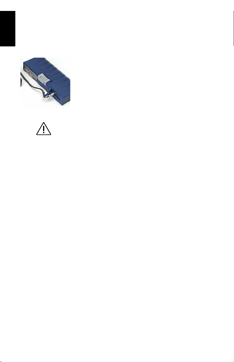
Replacing the Thales U-Link Transmitter Power Fuse
The Thales U-Link transmitter is protected by a 4-A fuse
inserted in the data/power cable. This Y-sha ped cable is used to
connect the U-Link transmitter to the Z-Max.Net re ceive r via a
7-pin connector, and to the power battery.
Should you have to replace this fuse, please get a spare fuse,
4 A, fast acting, ATO type, and then do the following:
- Unplug the battery end of the data/power cable
- Open the fuse holder located along the data/power cable
- Extract the damaged fuse
- Insert the new fuse and then push t he holder lid back into place
- Connect the data/power cable back to the battery.
Where to Find Information
This manual is designed to guide you through the basic
Z-Max.Net procedures. You can find additional information in
the Z-Max.Net Reference Manual, also provided on the
Z-Max.Net CD.
Warranties
Refer to the Z-Max.Net Reference Manual.

Table of Contents
Introduction..........................................................................1
System Components Overview ............................................... 1
Locating the Basic Components.............................................. 3
Z-Max.Net Front Panel............................................................ 3
Bluetooth® Port................................................................. 4
Status LEDs......... .................................. .. .......................... 4
Front Panel Display........................................................... 5
Control Keys...................................................................... 5
Power Key ......................................................................... 6
SD Card Reader and USB ................................................. 6
Z-Max.Net Rear Panel.............................................................6
GNSS Antenna Configurations ............................................... 7
Base ................................................................................... 7
Pole-Mounted Rover ....... .................................................. 7
Backpack-Mounted Rover................................................. 7
Preparing For First-Time Use .............................................8
Charging the Power Module.................................................... 8
Attaching the Lateral Modules ................................................ 9
Attaching the GNSS Antenna Module ....................................9
Inserting a Memory Card.......................................................10
Turning On/Off the System...................................................10
Initializing the System........................................................... 11
Checking that Z-Max.Net Receives Satellites....................... 12
RTK Surveying...................................................................13
RTK Surveying Method Requirements................................. 13
RTK Base Setup ....................................................................14
Choosing the Installation Site.......................................... 14
Setting Up the RTK Base ................................................ 14
RTK Rover Setup ..................................................................16
Establishing Bluetooth Communication with Z-Max.Net..... 18
Introduction ..................................................................... 18
Powering up the Whole Equipment................................. 19
Detecting Bluetooth-Enabled Devices ............................ 19
Finding Bluetooth Services ............................................. 20
Assigning Virtual Ports to Bluetooth .............................. 20
Saving Bluetooth Serial Port Settings ............................. 21
Defining/Saving Bluetooth Settings for FAST Survey... 22
Toggling Bluetooth Between Base and Rover................ 23
Configuring the RTK Base................ .................................... 23
Launching FAST Survey................................................. 23
Configuring the Base and the Data Link ......................... 24
Entering the Base Position and ID................................... 25
Setting the Radio ............................................................. 26
Configuring the RTK Rover.................................................. 27
Case #1: Rover Using a UHF Radio Data Link .............. 28
English

English
Case #2: Rover Using a GSM/GPRS Data Link............. 30
Saving Base and Rover Settings ........................................... 32
Running an RTK Survey....................................................... 32
Logging RTK Points....................................................... 33
Logging RTK Points in Continuous Mode ..................... 34
Staking out RTK Points .................................................. 35
Downloading RTK Results to GNSS Solutions.................... 37
Post-processing Surveying...............................................39
Reminder on the Static Surveying Method ........................... 39
Running a Static Survey........................................................ 40
Equipment Setup............................................................. 40
Getting the Z-Max.Net Unit Started in Static ................. 41
Starting Data Collection.................................................. 43
End of Data Collection.................................................... 43
Downloading Field Data to your PC..................................... 45
Post-Processing Field Data ......................... .......................... 46
Front Panel Interface Function Diagram..........................48

1. Introduction
Congratulations! You have just acquired your new dualfrequency Z-Max™.Net GNSS Surveying System from
Thales!
GNSS (or Global Navigation Satellite System) has
revolutionized control surveys, topographic data collection
and construction surveying. Purchasing the right tools for a
professional job is essential in today's competitive business
environment.
Learning to put these tools to work quickly and efficiently
will be the focus of the present guide.
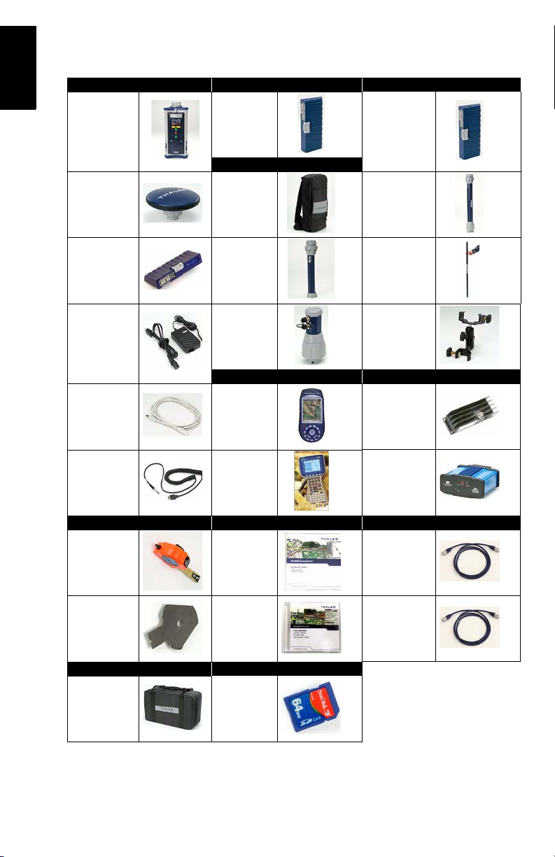
System Components Overview
The table below provides an overview of the different key
items composing the Z-Max.Net System. Depending on
your purchase, based on the type of survey you wish to
perform, you may only have part of the listed items. Please
refer to the delivered packing list for an accurate description
of the equipment that has been delivered to you.
Conversely, as this table is just an overview, it does not list
all the possible items and accessories. For example, the list
of all the possible field terminals is provided but we
intentionally do not mention the field brackets that usually
come along with them. For more information on these items,
please contact your dealer.
For ordering information, please refer to the Z-Max.Net
Reference Manual.
English
1
English
Basic Post-Processing Rover, RTK
GPS Receiver
Module
GNSS Antenna
Module
Power Module Range Pole
Charger
USB Cable
Serial Data
Cable
Static, Base Software RF Cables
V-Module (1)
(Void module)
Rover, Backpack
Backpack
RF Adapter
Max RF
Adapter
Field Terminal Radio
Thales
MobileMapper CE
Juniper
Allegro CX
Communication
Module
UHF Antenna
Module (2)
Range Pole
Mounting
Bracket
Thales U-Link
transmitter
Pacific-Crest
UHF Transmitter
HI measurement tool
eHI Measure-
ment Plate
Transport Case Memory Device
Soft case
GNSS Solutions CD
FAST Survey
CD
SD Card (sold
by Thales)
2
GPS-RF cable
UHF-RF cable
(1) Also used in an RTK base using a
UHF radio as the data link.
(2) A void UHF antenna module also
exists.
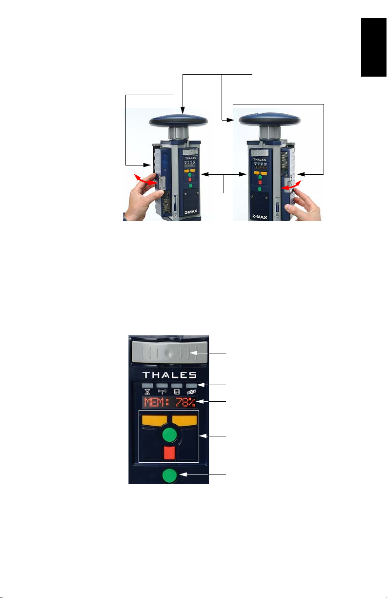
Locating the Basic Components
2. GNSS Antenna Module
3. Power Module 4. Communication Module
or V-Module
1. Receiver
Module
As you are facing the front panel of the GPS receiver
module, the power module attaches to the left-hand side of
the receiver module and the communication module (or Vmodule) to the right-hand side.
Z-Max.Net Front Panel
English
Z-Max.Net Bluetooth®
Status LEDs
Front Panel User Interface
Control keys
Power key
3
English
Bluetooth® Port
This device allows you to communicate with the Z-Max.Net
through a Bluetooth wireless connection. This port is
identified as “port C” on the Z-Max.Net.
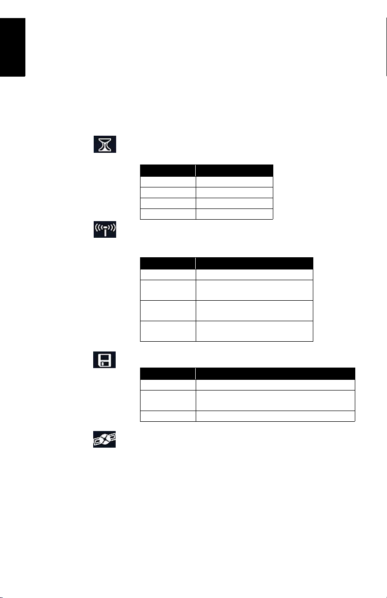
Status LEDs
From left to right, the LEDs are:
• RTK Solution. This LED is only operational when the
receiver is configured as an RTK rover.
Color Meaning
Off Not a RTK rover
Blinking green Fixed solution
Blinking orange Float solution
Blinking red No RTK solution
• Communication. This LED indicates when real-time
data is transmitted (base) or received (rover).
Color Meaning
Off No data link has been configured
Blinking green
Blinking red
Not blinking
Base: Transmits data
Rover: Base data received and used
Base: Irrelevant
Rover: Base data received but not used
Base: No data transmitted
Rover: No base data received
• Data Log. This LED shows the data logging status.
Color Meaning
Off No data logging in progress
Blinking green
Red Unable to log data (memory full)
Data logging in progress. Blinks at the frequency of the
recording interval setting (20 seconds by default).
• Satellite/Power. After po wer up, thi s LED will co nti nue
to blink red once every 1-2 seconds to indicate that the
unit is powered on. Between each red blink, the LED will
also blink green once for each satellite that the receiver is
tracking.
4

Up key
Enter key
Down key
Front Panel Display
The front panel display is an 8-character , alphanumeric LED
display that is used to monitor receiver status, set receiver
parameters and configure the receiver to perform different
types of surveys.
The screen displays up to eight characters at one time.
Messages or parameters longer than eight characters are
scrolled from right to left.
Control Keys
The four control keys are used in conjunction with the front
panel display. They will work differently depending on
whether the screen is in Display or Edit mode.
English
Cancel key
Display Mode:
Key Operation
UP (yellow) Scrolls menu (at same level) forward
DOWN (yellow) Scrolls menu (at same level) backward
ENTER (green) Selects and moves down to next level or enters Edit mode
CANCEL (red) Returns to upper level
Edit Mode:
Key Operation
Data entry context: Scrolls forward through characters
UP (yellow)
DOWN (yellow)
ENTER (green)
CANCEL (red)
Parameter list context: Scrolls forward
Fast scrolling if held depressed for 3 seconds
Data entry context: Scrolls backward through characters
Parameter list context: Scrolls backward
Fast scrolling if held depressed for 3 seconds
Parameter list context: Selects parameter
Data entry context: Accepts character and moves to next space
or quits Edit mode
Data entry context: Deletes last edited character, stays in Edit
mode
Parameter list context: Moves from Edit mode to Display mode
without selecting the parameter.
See Z-Max.Net Reference Manual for more information.
5

English
Power key
Power Key
This key is used to power up, power down or initialize the
unit (see
page 10).
SD Card Reader and USB
Below the four control keys is a small door fastened by two
thumbscrews. Unscrew the attaching screws and open the
door to reveal the SD Card slot and the USB port.
The SD card slot holds the SD card that serves as the
receiver's data storage memory . All data recorded by the unit
is stored on the SD card. Warning! Use exclusively SD
cards sold by Thales.
The USB port is one of the external ports available for
connecting to a computer. The USB port is a type-B
connector.
Z-Max.Net Rear Panel
Handle
External Power In (10-28 V DC)
Port A (RS232)
Port B (RS232 or RS422)
For connector pinout, see Z-Max.Net Reference Manual.
6
(A)
(B)
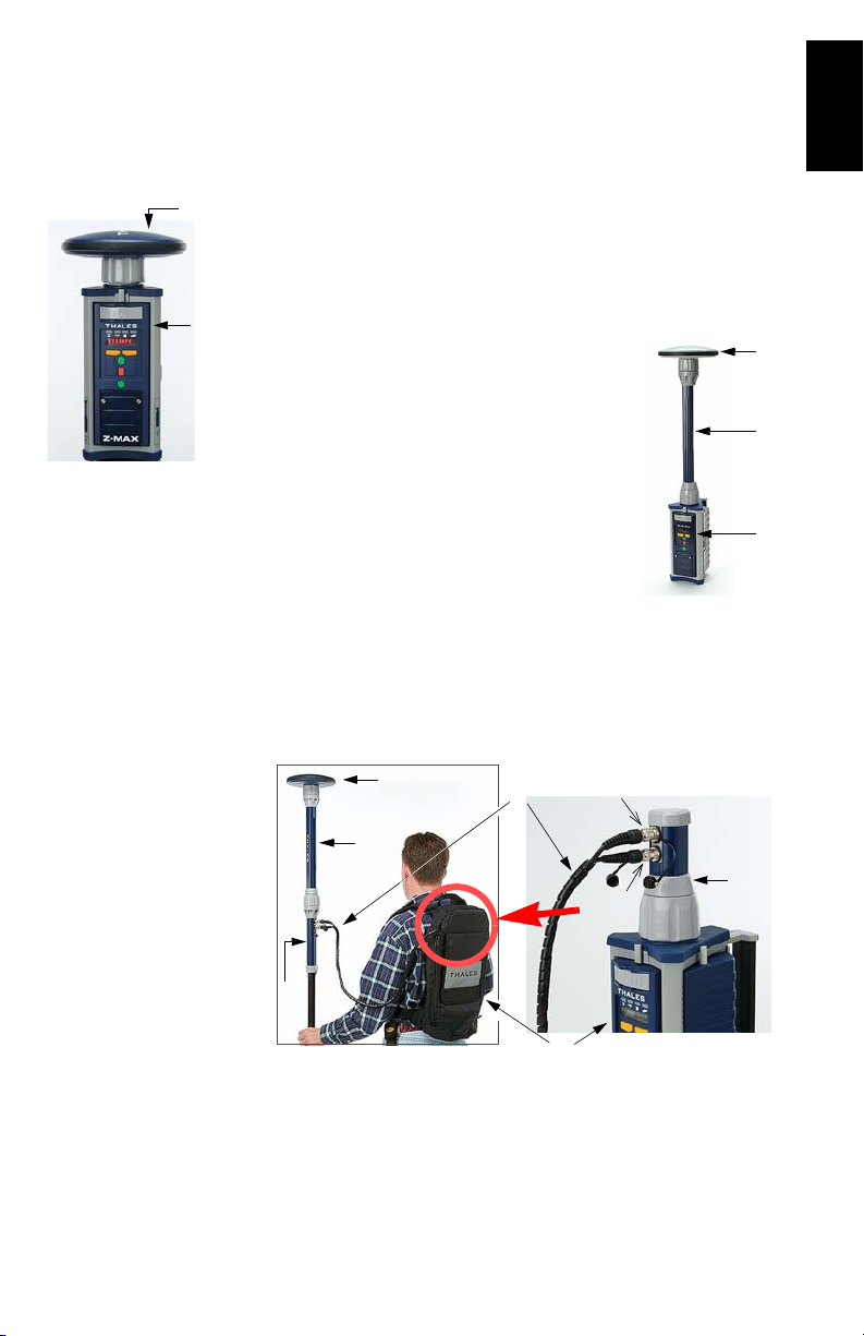
GNSS Antenna Configurations
In all cases of use, the GNSS antenna module must be
connected to the receiver module. But there are three
different ways of doing this, as explained below.
Base
The GNSS antenna module (A) is directly attached to the
receiver module (B).
(A)
Pole-Mounted Rover
The GNSS antenna module (A) is attached
to the receiver module (B) via a UHF
antenna module or a Void UHF antenna
module (C).
(C)
(B)
Backpack-Mounted Rover
The GNSS antenna module (A) is attached to the receiver
module (B) via a UHF antenna module or V oid UHF antenna
module (C), a range pole adapter (D), a dual RF cable (E)
and a Max-RF adapter (F).
English
(D)
(C)
(A)
(E)
GPS
(F)
UHF
(B)
7
English
Use of non-Thales power
supplies for charging the
power module is not
recommended.
2. Preparing For First-Time Use
Charging the Power Module
To charge the power module:
• Plug in your charger and connect the power module to
the charger as shown opposite.
•Charge for a minimum of five hours or preferably
overnight (even if the charger indicates that the battery is
full).
• Verify that the battery is fully charged by pressing the
button on the back side of the power module. The four
LEDs should light up green.
The power module contains rechargeable lithium-ion battery
cells and “smart” charging circuitry. Recharging the power
module is done using the AC/DC power supply, included
with the system.
This power supply can also be used to provide power
directly to the Z-Max.Net through an external connector.
The charger is designed to work with a 110-240 VAC power
source and delivers 12 V DC of input voltage with at least
4-A current capability to the power module.
For more information on the characteristics and management of the power module, see Z-Max.Net Reference Man-
ual.
8
Please take all precau-
tions to keep connector
pins clean and avoid
touching them.
Attaching the Lateral Modules
Whatever the type of module you are
attaching to the receiver module, i.e. a
power module on the left, or a commu
nication or V-module on the right, do
the following:
• Insert the small ledge of the module
into the rear of the housing first as
shown opposite (left and right).
This will correctly align the
module.
• Using the ledge like a hinge, start swinging the module.
To make sure the module is correctly positioned
vertically, take care to align the protruding edges, on
either side of the connector pins, with the grooves in the
receiver module casting. Then swing the module closed
until the latch on the module clicks into place.
• Make sure the module is well seated and the latch on the
edge of the module clicks shut.
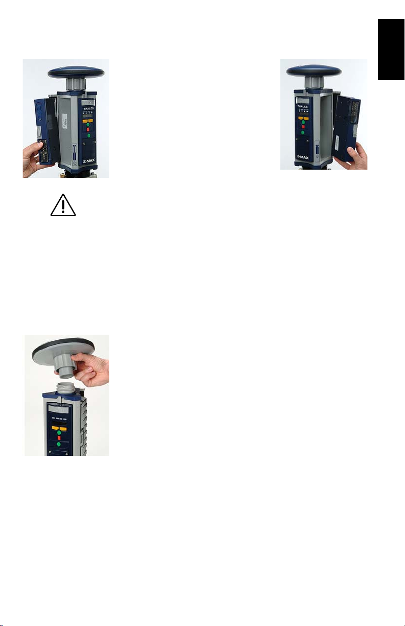
Attaching the GNSS Antenna Module
The base of the GNSS antenna module is circular except for
a flattened area. The top of the receiver module, UHF
antenna module or Void UHF antenna module is keyed so
there is only one way the GNSS antenna module can be
inserted.
• Make sure the base of the GNSS antenna module is
oriented so that the flattened area is lined up with the
flattened area of the receptacle.
• Once aligned, insert the GNSS antenna module into the
antenna receptacle. The module should push easily into
place.
English
9
English
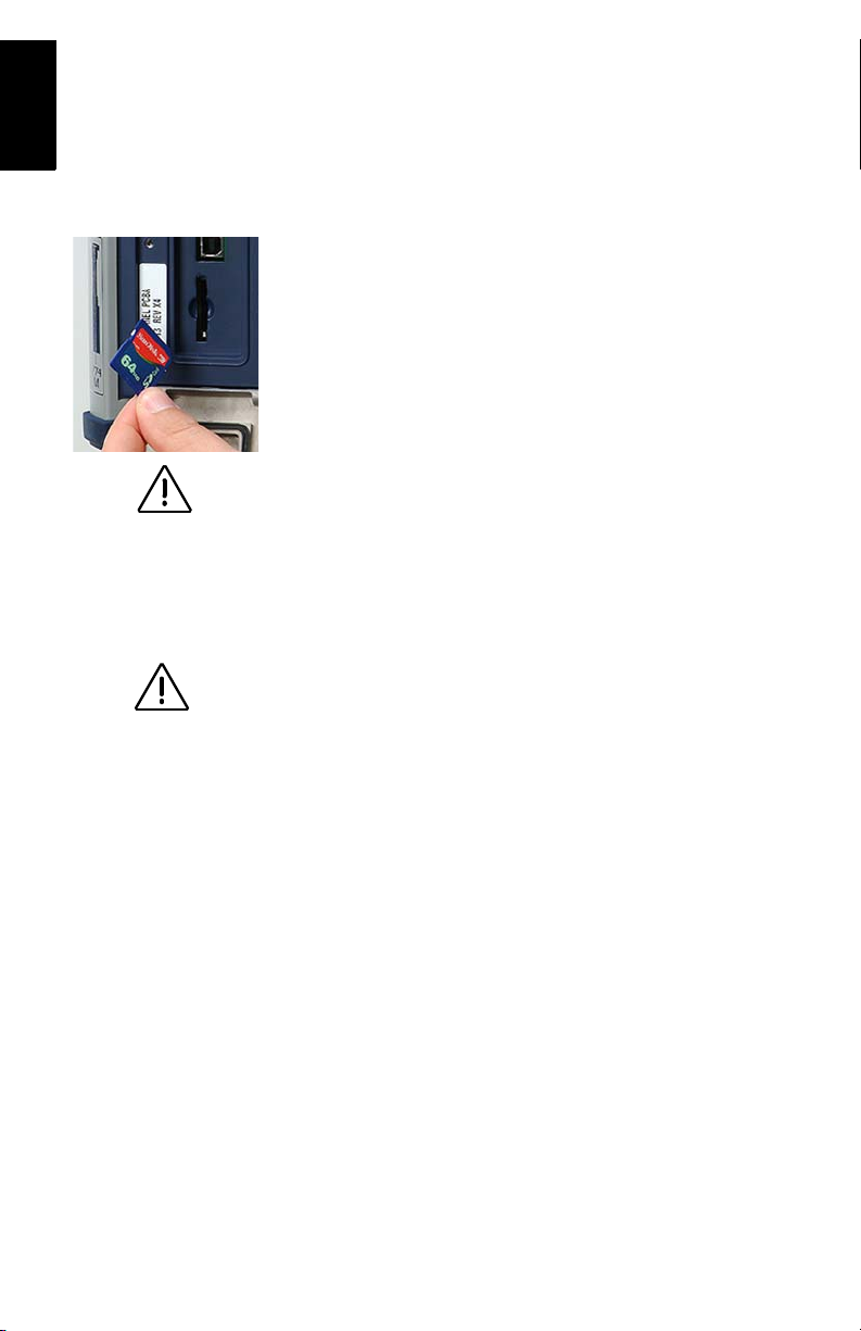
Use exclusively SD
cards sold by Thales!
It is important to power
off the receiver using
the Power key on the
Front Panel before
removing the SD card.
• Once in place, twist the threaded collar on the GNSS
antenna module until the antenna is securely locked in
place.
Inserting a Memory Card
A memory card is required if you want to run a post-processing survey or more generally, when you want to log raw data
with your Z-Max.Net.
To install the SD Memory Card into the reader:
• Orient it so that the chamfered corner of the card is
oriented downwards, as shown opposite.
• Gently push the card into the reader until you feel a soft
“click”. The click indicates that the card is properly
seated. A correctly inserted SD card should not move
once you have removed your hand from the card.
Turning On/Off the System
• Power on the system by pressing the Power button on the
receiver front panel for about 2 seconds (until a beep is
emitted) and then releasing the Power button.
The SV/Power LED should begin to blink red once per
second to indicate that the receiver is powered up.
• T o turn of f the system, just press and hold the power key
for two seconds. The receiver will generate a beep every
second, a “shutdown” message will be displayed, and the
receiver will then power down.
10

Initializing the System
Initializing the system is recommended the first time you use
your system to:
• Clear the internal memory
• Reset the user settings to their default values
• Clear ephemeris and almanac information in memory
• Re-format the SD card. Note that initialization should
also be performed every time you prepare your SD card
for a new survey project. It’s al ways bett er to de lete f i les
from the SD Card by running an initialization sequence
rather than using any other method.
Initializing the system is also appropriate any time the
Z-Max.Net does not work as expected.
T o initialize the system from the Power button, assuming the
system is off, do the following:
• Press the Power button for at least 5 seconds.
The display will show “re-init”, indicating that the
receiver is in the initialization process.
The initialization process will take several minutes
depending on the size of the SD card. The front panel
will continue to display “
plete.
When complete, the receiver will be powered on and in
the normal state with the front panel displaying
“
SYSINFO” and the SD card ready to use.
re-init” until the process is com-
English
11

English
Please go outside after
initialization and make
sure your system has a
clear view of the sky in
all direct ions.
Checking that Z-Max.Net Receives Satellites
If the GPS antenna has a reasonably good view to the sky,
within a few minutes, the receiver should begin to track satellites. This is indicated by the SV/Power LED:
1. It should blink red once per second to indicate that power
is on, and blink green several times between each red
blink.
2. It will blink green once for each satellite that is being
tracked. In normal conditions of reception, the system
should receive about eight satellites on average.
12
3. RTK Surveying
When the base setup is
under your responsibil-
ity, make sure the base
is sited in a clear area
giving the best possible
view of the sky!
When this is possible,
avoid trees, buildings or
any high obstacles in the
vicinity of the base.
Having a clear view of
the sky will allow the
base to collect data from
a maximum of visible
satellites, which is highly
recommended to perform
a successful, accurate
and fast survey.
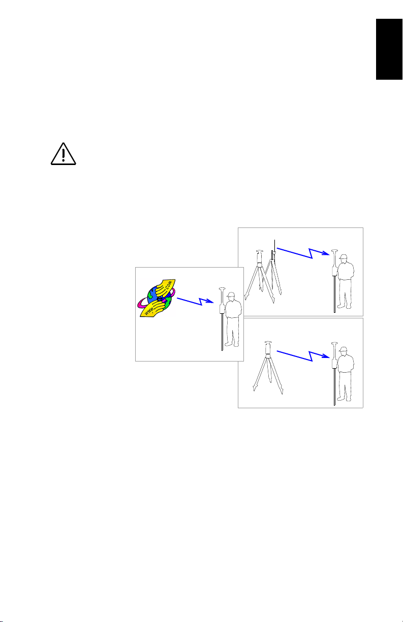
RTK Surveying Method Requirements
Key information is provided below.
1. Two units are needed: one (the base) is operated on an accurately known
position while the other (the rover) is used in the working area.
2. A data link must be established from the base to the rover. This data link
can be implemented in three different ways:
- UHF radio
- Cellular modem (GSM)
- Other external device
3. Depending on the chosen data link, the base will be either:
- A “real” base system (with UHF radio, GSM, or other external device)
- Or a “virtual” base system that delivers its data via a cellular modem
(GPRS).
The main Z-Max.Net RTK system configurations are illustrated below:
GPRS
Internet
Data Link
Rover
UHF Radio
Base
GSM
Base
Data Link
Data Link
Rover
Rover
English
4. Two different rover setups can be used, backpack or range pole, yet
operated similarly. Only the pole-mounted rover system will be described
in this Guide. For more information on the backpack mounting, refer to the
Z-Max.Net Reference Manual.
5. RTK is easier to operate using a field terminal running FAST Survey. RTK
can also be operated from the receiver front panel display.
6. Whatever the base used (“real” or “virtual”), its distance to the rover, called
“baseline” (up to 50 km or 30 miles), must roughly be known to make sure
RTK results will achieve the expected level of accuracy.
13
 Loading...