

Page 1
USER GUIDE
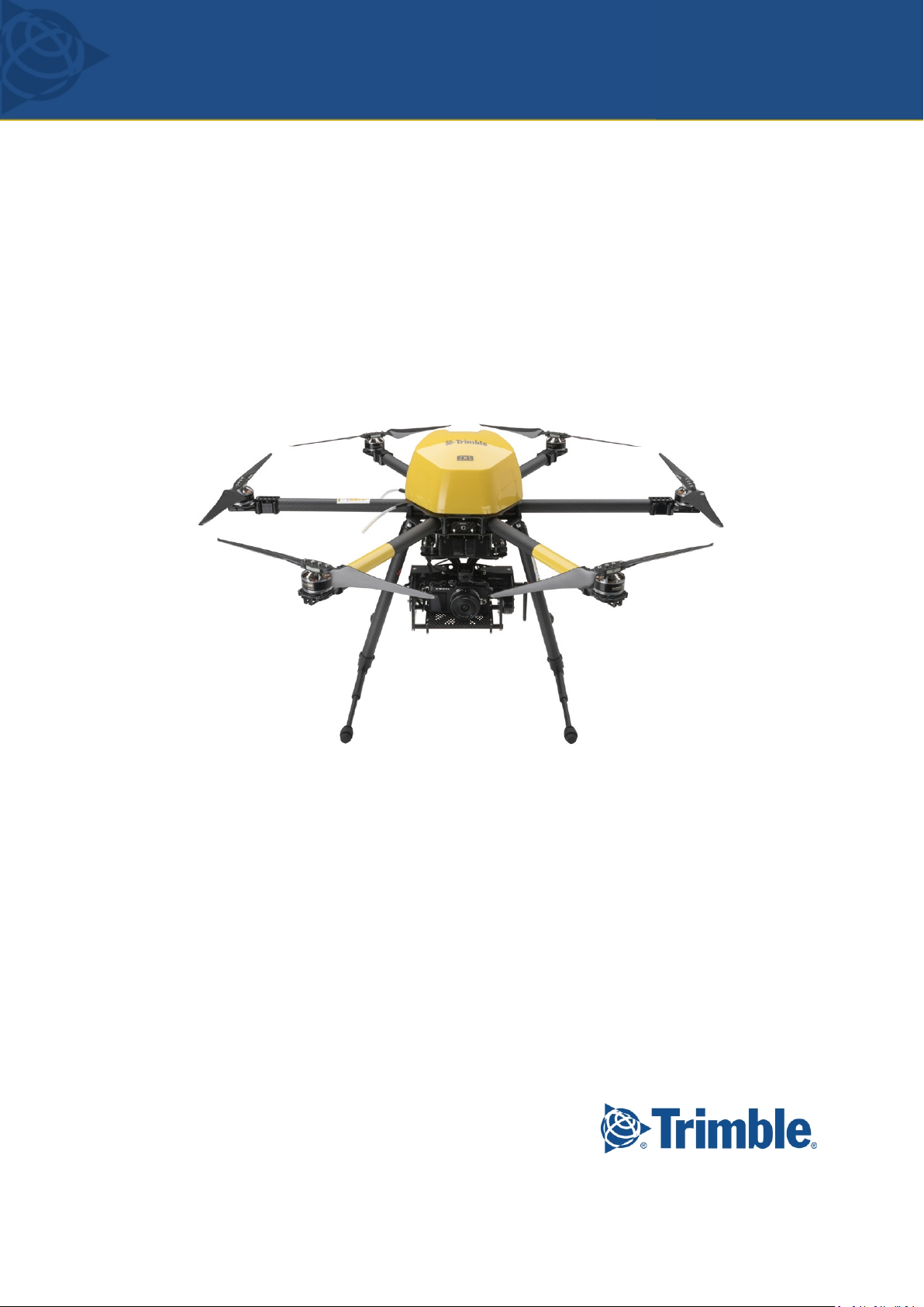
Trimble ZX5
Version1.0.0
RevisionA
March2016
1
Page 2

Legal Information
Trimble Navigation Limited
935 Stewart Drive
Sunnyvale, California 94085
U.S.A.
www.trimble.com
Copyright and Trademarks
© 2013–2016, Trimble Navigation Limited. All rights
reserved.
Trimble and the Globe and Triangle logo are
trademarks of Trimble Navigation Limited, registered
in the United States and in other countries. Access is a
trademark of Trimble Navigation Limited.
Microsoft and Windows are either registered
trademarks or trademarks of Microsoft Corporation in
the United States and/or other countries.
The Bluetooth word mark and logos are owned by the
Bluetooth SIG, Inc. and any use of such marks by
Trimble Navigation Limited is under license.
Wi-Fi is a registered trademark of the Wi-Fi Alliance.
All other trademarks are the property of their
respective owners.
COCOM Limits
The U.S. Department of Commerce requires that all
exportable GPS products contain performance
limitations so that they cannot be used in a manner
that could threaten the security of the United States.
The following limitations are implemented on this
product:
– Immediate access to satellite measurements and
navigation results is disabled when the receiver
velocity is computed to be greater than 1,000 knots,
or its altitude is computed to be above 18,000 meters.
The receiver GPS subsystem resets until the COCOM
situation clears. As a result, all logging and stream
configurations stop until the GPS subsystem is
cleared.
Notices
United States
Certification number:
FCC ID ONTJETIDS16US; ONTJETIR5US.
This equipment has been tested and found to comply
with the limits for a Class A digital device, pursuant to
part 15 of the FCC Rules. These limits are designed to
provide reasonable protection against harmful
interference when the equipment is operated in a
commercial environment. This equipment generates,
uses, and can radiate radio frequency energy and, if
not installed and used in accordance with the
instruction manual, may cause harmful interference to
radio communications. Operation of this equipment
in a residential area is likely to cause harmful
interference in which case the user will be required to
correct the interference at his own expense.
Changes and modifications not expressly approved by
the manufacturer or registrant of this equipment can
void your authority to operate this equipment under
Federal Communications Commission rules.
Canada
Under Industry Canada regulations, this radio
transmitter may only operate using an antenna of a
type and maximum (or lesser) gain approved for the
transmitter by Industry Canada.
To reduce potential radio interference to other users,
the antenna type and its gain should be so chosen
that the equivalent isotropically radiated power
(e.i.r.p.) is not more than that necessary for successful
communication.
This device complies with Industry Canada licenseexempt RSS standard(s). Operation is subject to the
following two conditions:
(1) this device may not cause interference, and
(2) this device must accept any interference, including
interference that may cause undesired operation of
the device.
This Class A digital apparatus complies with Canadian
ICES-003.
Certification number:
IC 10491A-JETIDS16US; 10491A-JETIR5US.
This apparatus complies with Canadian RSS-210.
Conformément à la réglementation d'Industrie
Canada, le présent émetteur radio peut fonctionner
avec une antenne d'un type et d'un gain maximal (ou
inférieur) approuvé pour l'émetteur par Industrie
Canada.
Dans le but de réduire les risques de brouillage
radioélectrique à l'intention des autres utilisateurs, il
faut choisir le type d'antenne et son gain de sorte que
la puissance isotrope rayonnée équivalente (p.i.r.e.)
ne dépasse pas l'intensité nécessaire à l'établissement
d'une communication satisfaisante.
Le présent appareil est conforme aux CNR d'Industrie
Canada applicables aux appareils radioexempts de
licence. L'exploitation est autorisée aux deux
conditions suivantes:
(1) l'appareil ne doit pas produire de brouillage, et
(2) l'utilisateur de l'appareil doit accepter tout
brouillage radioélectrique subi, même si le brouillage
est susceptible d'en compromettre le fonctionnement.
Cet appareil numérique de la classe A est conforme à
la norme NMB-003 du Canada.
Numérique de certification IC: 4492A-DNT2400P.
Cet appareil est conforme à la norme CNR-210 du
Canada.
Trimble ZX5 User Guide 2
Page 3
Europe
The product covered by this guide are intended to be
used in all EU member countries, Norway, and
Switzerland.
This equipment is classified as Group 1, Class A
equipment according to EN 55011. Group 1 is
applicable for all equipment within the scope of EN
55011 that is not classified as Group 2 equipment,
which contains all ISM RF equipment. Class A
equipment is equipment suitable for use in all
establishments other than domestic. Using Class A
equipment in domestic environments may cause
difficulties ensuring electromagnetic compatibility.
CE Declaration of Conformity
Hereby, Trimble Navigation, declares that
this product is in compliance with the
essential requirements and other relevant
provisions of:
– EMC Directive (2004/108/EC)
– Radio Equipment Directive (1999/5/EC)
– RoHS Directive (2011/65/EU)
– Machine Directive (2006/42/EC)
Japan
Certification numbers for the DNT2400P RFM radio
module: 007WWCUL0739 and 003UVA110681
Australia and New Zealand
This product conforms with the regulatory
requirements of the Australian
Communications and Media Authority
(ACMA) EMC framework, thus satisfying the
requirements for C-Tick Marking and sale within
Australia and New Zealand.
Taiwan – Battery Recycling Requirements
The product contains a removable lithium polymer
battery. Taiwanese regulations require that waste
batteries are recycled.
廢 電 池 請回 收
Waste Electrical and Electronic Equipment (WEEE)
For product recycling instructions and more
information, please go to
www.trimble.com/Corporate/Environmen
tal_Compliance.aspx.
Recycling in Europe: To recycle Trimble WEEE (Waste
Electrical and Electronic Equipment, products that run
on electrical power), call +31 497 53 24 30, and ask for
the “WEEE Associate”. Or, mail a request for recycling
instructions to:
Trimble Europe BV
c/o Menlo Worldwide Logistics
Meerheide 45
5521 DZ Eersel, NL
FCC Declaration of Conformity
We, Trimble Navigation Limited.
935 Stewart Drive
PO Box 3642
Sunnyvale, CA 94088-3642
United States
+1-408-481-8000
Declare under sole responsibility that DoC products
comply with Part 15 of FCC Rules.
Operation is subject to the following two conditions:
(1) This device may not cause harmful interference,
and
(2) This device must accept any interference
received, including interference that may cause
undesired operation.
Trimble ZX5 User Guide 3
Page 4

Environmental hazards
The product complies with international RoHS regulations.
Toxic and hazardous substances and elements
Part name Lead
(Pb)
Battery
Lithium polymer
rechargeable battery
Cables
Internal wiring
LCD Display
Keypad
Motor
Power adapter
Power supply
Printed circuit board
assembly
Radio module
Chassis
O O O O O O
O O O O O O
O O O O O O
X O O O O O
O O O O O O
O O O O O O
O O O O O O
O O O O O O
X O O O O O
X O O O O O
X O O O O O
O O O O O O
Mercury
(Hg)
Cadmium
(Cd)
Hexavalent
Chromium
(Cr6+)
Poly-brominated
biphenyls
(PBB)
Poly-brominated
diphenyl ethers
(PBDE)
Enclosure
Hardware
Paper manual
O O O O O O
O O O O O O
O O O O O O
Trimble ZX5 User Guide 4
Page 5

Contents
Safety
1 Introduction
The Trimble ZX5 9
ZX5 system components 9
ZX5 UAV 10
Camera gimbal 16
Ground control station 17
2 Preparing Equipment
Transportation 20
Checking the ZX5 aerial imaging rover 21
Checking the GCS 24
Checking the ZX5 battery pack 24
Charging the ZX5 battery pack 24
Pre-flight acoustical signals 30
Charging the camera batteries 30
Configuring the camera settings 31
3 Operating the ZX5 Using the Remote Control
Controls on the remote control unit 33
Main functions 34
Camera functions 35
Additional functions 35
Flight functions 36
Remote control software menus 40
Remote control in-flight announcements 45
7
8
19
32
4 Completing a Flight
Checking flight permissions and conditions 48
Flight time 51
Pre-flight checks 51
Emergency failsafe functions 53
Ending the flight 54
5 Troubleshooting
Updating the ZX5 firmware 57
Calibrating the compass 58
Technical support 59
6 Specifications and Settings
Operation limitations 61
ZX5 specifications 62
Remote control specifications 63
47
56
60
Trimble ZX5 User Guide 5
Page 6

Contents
A Country-Specific Regulatory Information
FAA conditions and limitations of operation 66
B Learn to Fly Tutorials
Tutorial 1: Position hold, flying in GPS mode 71
Tutorial 2: Start, hover and land in manual mode 72
Tutorial 3: Auto start assistant 73
Tutorial 4: Auto landing assistant 74
Tutorial 5: Coming Home 75
Tutorial 6: Easy Move 76
65
70
Trimble ZX5 User Guide 6
Page 7

Contents
Safety
WARNING – Failure to read and follow the instructions, warnings and recommendations in this guide
can lead to loss of control of the ZX5. Loss of control of the ZX5 can lead to a crash, causing damage to
equipment and property and/or serious personal injury or even death. Make sure to familiarize
yourself regularly with the contents of this guide.
WARNING – The Trimble ZX5 is not a toy. Misuse of this aircraft may result in serious injury or death of
the operator and spectators. The ZX5 must only be operated by trained personnel. Training is available
from Trimble-certified trainers.
WARNING – Always keep a minimum safety distance of 10m (33ft) between the ZX5 and any person
who is not directly responsible for operating the aircraft. Never fly directly over gatherings of people
or traffic on the ground.
WARNING – Contact with moving parts can result in serious personal injury. Do not touch the ZX5
when the propellers are rotating. Before starting the ZX5 make sure all personnel and objects are at a
minimum safety distance of 3m (10ft).
WARNING – For safety reasons, after landing the motor speed can increase again after 2seconds
under certain circumstances. To avoid injury from suddenly moving parts, immediately shut down the
ZX5 motors completely, even if you intend to restart the ZX5. To do this, pull the throttle stick on the
remote control all the way down and move the motor switch to the Off position. Attempting to restart
the ZX5 when the motors are idling can cause loss of control of the ZX5 and lead to a crash directly
after take-off.
WARNING –Loss of control of the aircraft can result in equipment damage, property damage, serious
personal injury, or death. To minimize the risk of loss of control, observe the following at all times:
– Do not fly near other objects in the air.
– Do not fly on rainy or windy days or at night.
– Do not fly near high tension lines, electrical substations, high structures, or communication facilities.
– Never fly this aircraft where damage to property or injury to persons may result if loss of control
occurs.
– Always maintain visual line of sight between you on the ground and the ZX5 in the air.
– Always be prepared to make an emergency landing, without endangering others or damaging their
property.
WARNING –Always inspect the ZX5 carefully after a hard landing or a crash. Damage to parts can
cause unstable flight characteristics, which may lead to loss of control of the aircraft.
WARNING –Lithium polymer batteries are volatile. Make sure to read and understand all information
regarding battery charging and use in this document and the Trimble ZX5 Lithium Polymer Batteries
Precautions guide.
Trimble ZX5 User Guide 7
Page 8

Introduction
C H A P T E R
1
n The Trimble ZX5
n ZX5 system components
n ZX5 UAV
n Camera gimbal
n Ground control station
The Trimble ZX5 User Guide provides detailed
information about operating the components of
the Trimble® ZX5.
Even if you have used other unmanned aviation
systems before, please read this user guide
carefully to familiarize yourself with the ZX5.
Trimble ZX5 User Guide 8
Page 9
1 Introduction
The Trimble ZX5
The Trimble ZX5 is an unmanned aerial vehicle (UAV). An unmanned aerial vehicle is a generic term,
and refers to an aircraft that is operated remotely. The ZX5 is a radio controlled, electric powered
aircraft capable of vertical starts and landings. Using electronic sensors and an integrated GPS
receiver, it is self-stabilising in every direction. The ZX5 is able to fly to pre-set waypoints by itself
and also hold its position under windy conditions.
The camera takes aerial images over the defined area. During the flight, the pictures are acquired at
a specified height, along parallel lines with specified overlap between the image exposures. At the
same time, position information of the pictures is recorded for further processing in image
processing software such as Trimble Business Center software.
The high-performance control unit in the ZX5 provides high accuracy. The ZX5 is controlled by
remote control. For extra control, it is possible for the ZX5 and the camera to be controlled
independently using two different control units. This allows the pilot to concentrate on flying while
the camera operator takes care of the ideal camera view to obtain the best pictures.
To assist with repeated air activity the ZX5 is able to learn waypoints and fly them semiautomatically.
The ZX5 is shipped with an optional Inspection Module, which contains the video receiver to allow a
live video feed during flight.
ZX5 system components
The ZX5 aerial imaging system comprises the following components:
l ZX5 UAV
l Camera gimbal, mounted below the UAV
l Ground control station (GCS) for pilot, with or without a video receiver
or
Trimble ZX5 User Guide 9
Page 10

1 Introduction
ZX5 UAV
The ZX5 comprises the following parts:
l ZX5 frame, page 10
l Propellers, page 11
l Battery pack, page 11
l Dome, page 13
l Connectors, page 13
l Remote control receiver with antenna, page 14
l Video transmitter with antenna , page 15
l Flight recorder, page 15
l Pre-flight acoustical signals
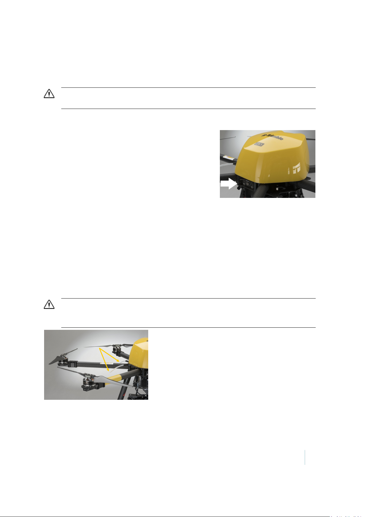
ZX5 frame
The ZX5 is built symmetrically. The front is between the two yellow extension arms.
Trimble ZX5 User Guide 10
Page 11
1 Introduction
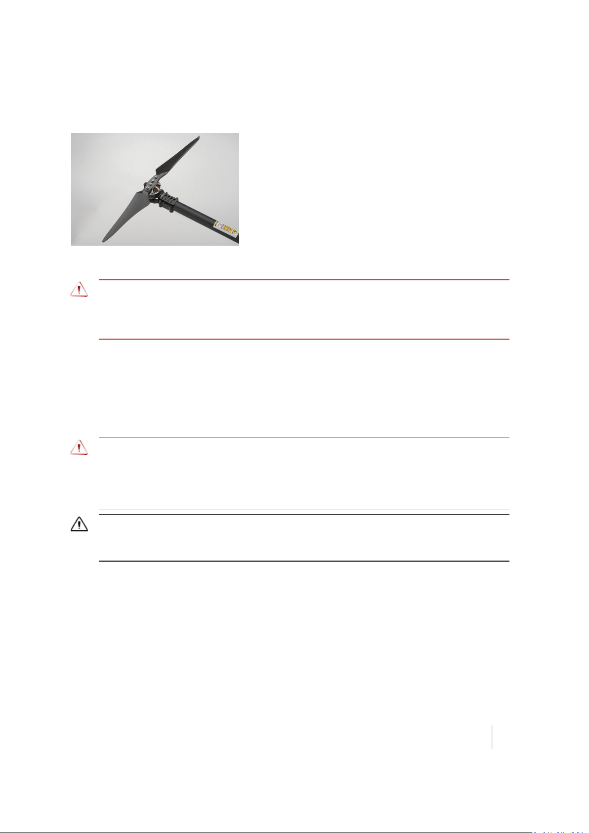
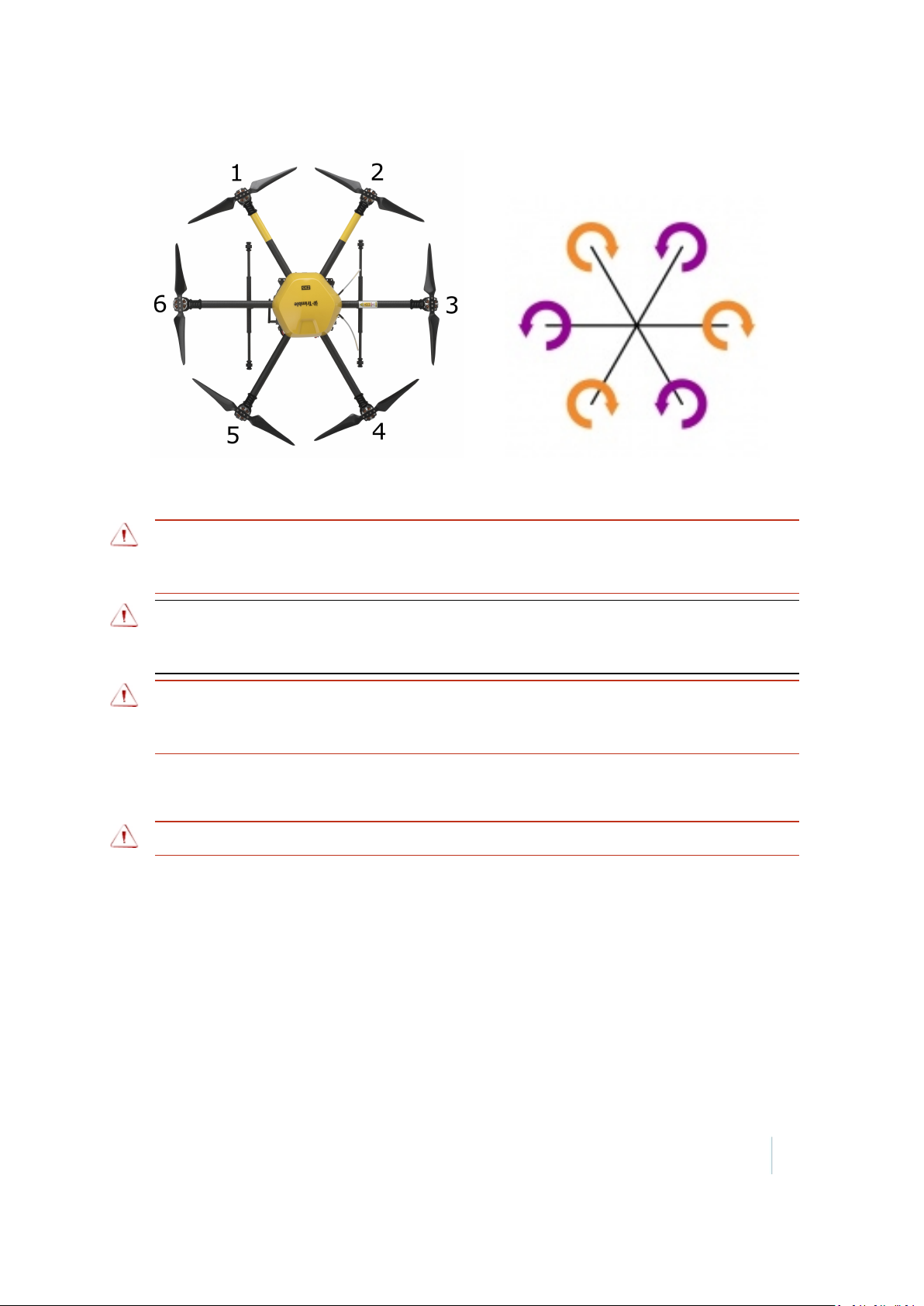
Propellers
The folding propellers are pre-installed on the ZX5.
There are two different rotation directions for the propellers: clockwise and counter-clockwise. Each
propeller must be attached to the appropriate motor so that the ZX5 can fly safely.
WARNING – Always ensure propellers are fitted to the correct motor. If one or more propellers are
fitted to a motor that rotates in the opposite direction to the propeller, the ZX5 cannot fly correctly
causing loss of control. Loss of control of the ZX5 may lead to a crash, resulting in equipment damage,
property damage, or personal injury.
The propellers are very light, but also fragile in case of a hard landing. Each folding propeller is a unit
made of two blades and a center piece. The propeller unit is dynamically balanced during
manufacture to operate at 8000 rpm. The propellers must be properly balanced to avoid vibrations
during flight. Make sure the propellers are kept clean. For more information, see Check the
propellers, page 22.
Avoid contact with other objects during transportation and flight. Fold the propellers before
storing the ZX5 in the flight case. For more information, see Transportation, page 20.
WARNING – Never fly with a damaged propeller. Always replace a damaged propeller before the next
flight. Always replace the full propeller, not just a single blade as the two blades are dynamically
balanced. Exchanging only one blade will create vibration. A damaged propeller can cause loss of
control of the ZX5 which may lead to a crash, resulting in equipment damage, property damage, or
personal injury.
CAUTION – Make sure the propellers are properly balanced before flight to avoid unnecessary
vibration. Vibration can cause blurred and out of focus images or affect the flight characteristics of the
ZX5, causing damage to the ZX5 or loss of control.
For maintenance of the propellers, refer to the Trimble ZX5 Maintenance Guide.
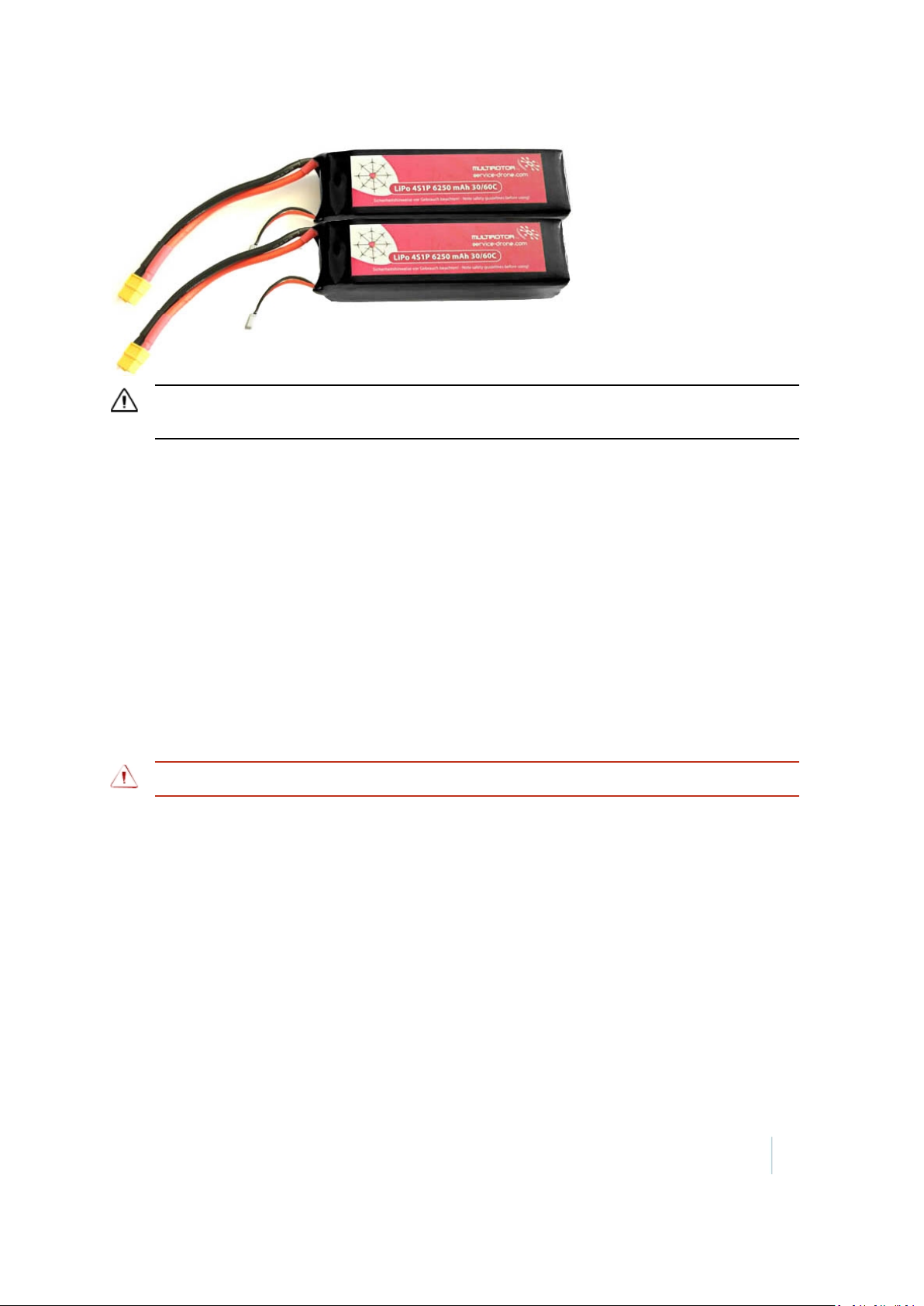
Battery pack
The ZX5 is operated by two high-power lithium polymer batteries connected in parallel. To get the
best performance and lifetime, the two batteries should always be used together. The pair of
batteries is only as good as the bad battery.
Trimble ZX5 User Guide 11
Page 12
1 Introduction
CAUTION –Do not separate the battery pack. Always use the complete battery pack for the lifetime of
the poorest battery. Attempting to separate the battery pack will damage the batteries.
Lithium polymer batteries are characterized by their low weight, high capacity and high power
output.
Correct handling of the batteries is essential to delay the inevitable aging of the battery cells. With
time and use the voltage level of the cell is reduced and the inner resistance is increased. The
batteries deliver less current.
To delay the aging process:
l Use the batteries regularly (approximately once per month).
l If the ground control station warns "Low battery" during flight, end the flight, let the battery
cool (wait 30-45 minutes), and then recharge it. Lithium polymer batteries have no memory
effect, and fully discharging them will only shorten their life.
Always recharge the battery pack before use. For more information, see Charging the ZX5 battery
pack, page 24.
Storing the battery pack
WARNING – LiPo batteries should never be stored at full charge for more than a few hours at most.
Note – The charger can only charge a battery; it cannot discharge a battery.
Stored batteries should be recharged every three months.
For optimal battery life, store the ZX5 batteries in a cool, dry area (below 15–20 °C / 59–68 °F) that is
subject to little temperature change.
During flight the temperature of the battery is regulated due to the flow of current. When not in
flight, elevated temperatures can result in reduced battery service life. Do not place batteries near
heating equipment, nor expose to direct sunlight for long periods. Do not store or transport
batteries above 60 °C (140 °F) or below 10 °C (50 °F). Extreme temperatures will result in the battery
venting flammable liquid and gases. Do not store the battery inside a vehicle. Temperatures inside
a vehicle can rapidly exceed the recommended maximum storage temperature.
Batteries should be separated from other materials and stored in a noncombustible, well
ventilated, sprinkler-protected structure with sufficient clearance between walls and battery stacks.
Trimble ZX5 User Guide 12
Page 13
1 Introduction
Dome
The dome contains the main board that controls the ZX5. The main board is connected to a GPS
antenna for navigation, and other electronic sensors such as gyroscope, accelerometer and
compass for flight stability. The main board is also connected to a remote control receiver for
communicating with the ground control station. If you have the optional Inspection Module, the
main board is also connected to a video transmitter antenna for a live video stream.
Always detach the battery pack before removing the dome. To disassemble the dome, unplug the
connectors and lift it up.
You must remove the dome to:
l Update the firmware.
l Attach the cables of the servos.
l Attach the cable of the camera trigger.
l Remove the flight recorder micro SDcard to obtain the GPS data and recorded images.
Connectors
The ZX5 has the following connectors:
l 6 x 3-pin connectors for up to 4 servo motors and 1 camera trigger.
l Socket for video access.
l Socket for firmware update.
l Socket for data cable.
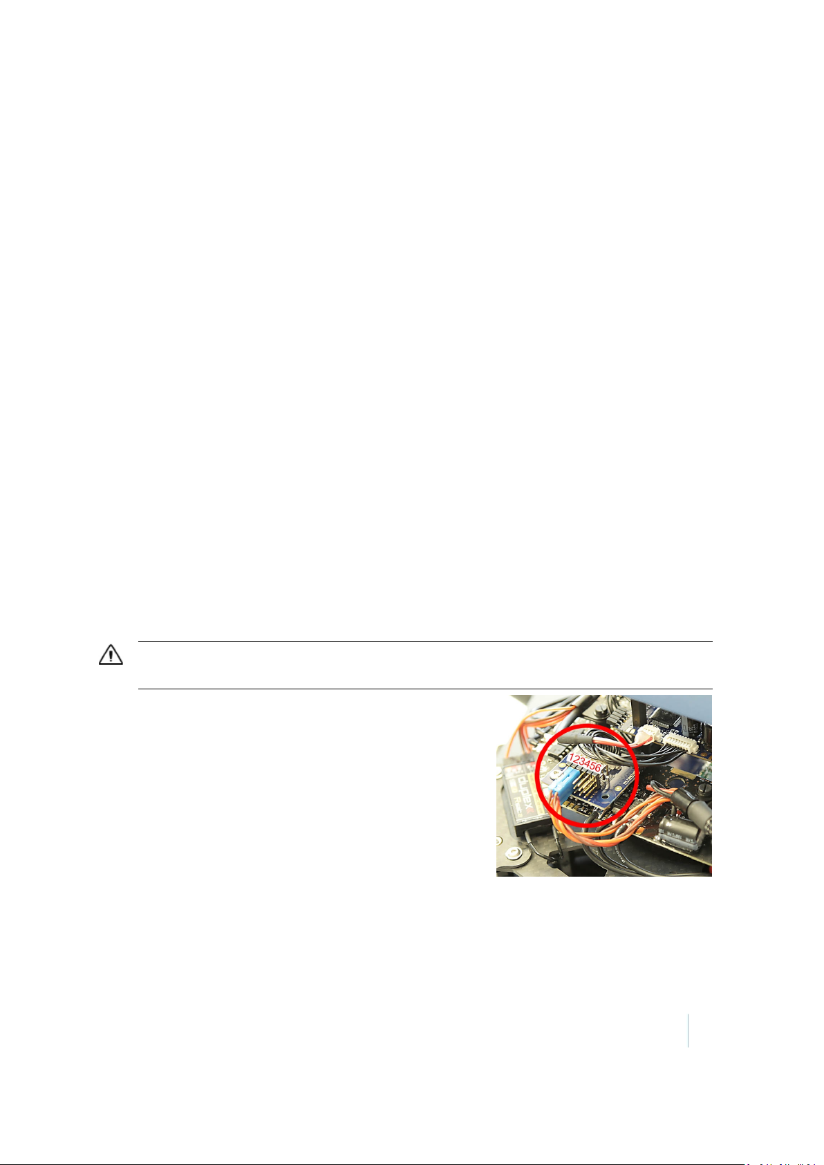
Servo connectors
The connectors for the camera mount servos are located under the dome.
CAUTION –To avoid damaging the electronics, disconnect the power supply before attaching or
detaching the servo cables.
The connectors are consecutively numbered from left to right
as shown:
1. Roll compensation
2. Pitch compensation
3. Trigger for camera
4. No function
5. No function
6. No function
Trimble ZX5 User Guide 13
Page 14
1 Introduction
Firmware update connector
Make sure to keep the firmware up to date. For more information, see Updating the ZX5 firmware,
page 57.
CAUTION –To avoid damaging the electronics, avoid contact with the electronic devices and
conducting paths on the board.
Data connector
The data cable port is for connecting the data cable to upload
missions created using the GroundStation software.
Before connecting to the ZX5 for the first time, make sure the
computer running the GroundStation software has an
Internet connection so that the appropriate drivers can be
downloaded automatically. For more information, refer to
the GroundStation Software for the Trimble ZX5 User Guide.
Note – Installation make take some time. If you experience
issues installing the drivers, go to
www.ftdichip.com/Drivers/VCP.htm.
Before uploading the mission, connect the data cable to the indicated port below the dome and to
the USB port of the computer that has GroundStation installed.
During flight, the ZX5 records the GPS coordinates for each photo location. Use the data cable to
download the GPS coordinates after the flight, so that the images can be synchronized with the
correct coordinates.
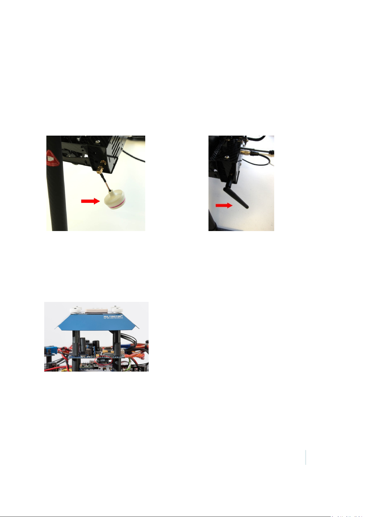
Remote control receiver with antenna
The remote control receiver works in a range of 2.4 GHz, using a dipole-antenna to keep
interference as low as possible. The yellow antennas are secured by a flexible hose.
CAUTION –Take care never to bend the antennas. The antennas should be aligned in a straight line
and at a 90° degree angle to each other. Damaged antennas may reduce the range of the remote
control and cause loss of control of the ZX5.
Trimble ZX5 User Guide 14
Page 15
1 Introduction
Video transmitter with antenna
This is available with the Inspection Module only.
The video transmitter is installed into the camera gimbal. It works in a frequency range of 5.8 GHz.
It is connected with the video antenna shown. The antenna can be adjusted by turning it at the
plug. Find the ideal position for reception by trying. This will vary, depending on the external
conditions and the camera in use (shadowing effects).
Note – Avoid obstacles or barriers between the ZX5 and the video receiver as they can cause
image interference.
Flight recorder
A micro SD card slot is located on the flight control panel beneath the dome. The flight recorder
uses the micro SD card to memorize all system and sensor data during the flight. If you should have
problems with the ZX5 you can import the flight data on the SD card to your computer and then
send it to your Trimble distributor. To get to the board you must remove the dome. Press onto the
card to release it.
The ZX5 can be started only when the micro SD card provided with your system is inserted. If you
lose or damage your card, contact your Trimble distributor.
Trimble ZX5 User Guide 15
Page 16
1 Introduction
CAUTION –The micro SD card contains data files that can be read only with the appropriate software.
Damage to the data on the micro SD card can render the ZX5 and the micro SD card unusable. To
avoid damaging the data:
– Do not reformat the micro SD card.
– Do not copy data from the micro SD card.
– In case of a crash, do not power on the ZX5 afterward as this can cause overwriting of the latest flight
data and the reason for the problem cannot be analyzed.
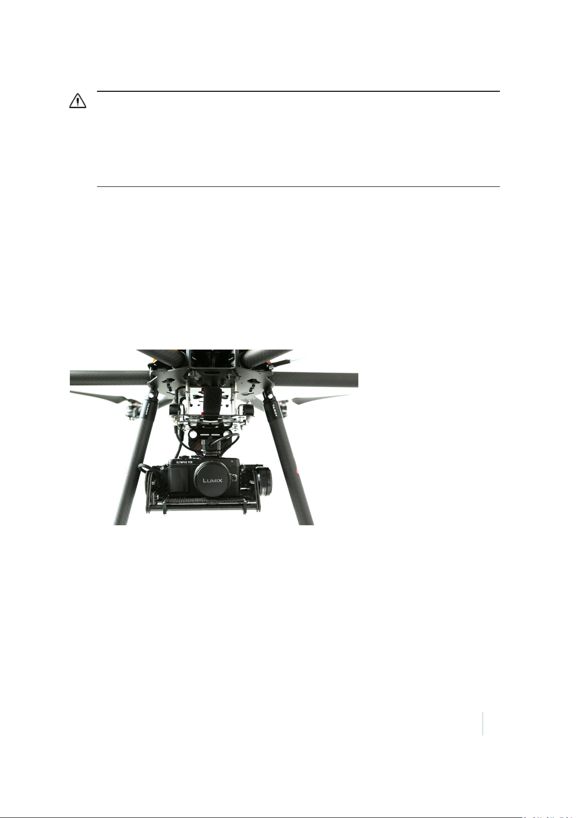
Camera gimbal
The camera gimbal holds the camera. It is attached to the ZX5 frame below the dome. The camera
gimbal provides a straight and stable picture even if the ZX5 flies askew to move or to travel against
the wind.
The roll and yaw axis are controlled by brushless motors and their own stabilising unit. The camera
can be adjusted manually to define the needed pitch to focus the desired object.
The gimbal is powered with its own power switch, located at the side of the gimbal. Beside the
power switch there is a small push button for calibration. For more information, refer to the
Trimble ZX5 Maintenance Guide.
Trimble ZX5 User Guide 16
Page 17
1 Introduction
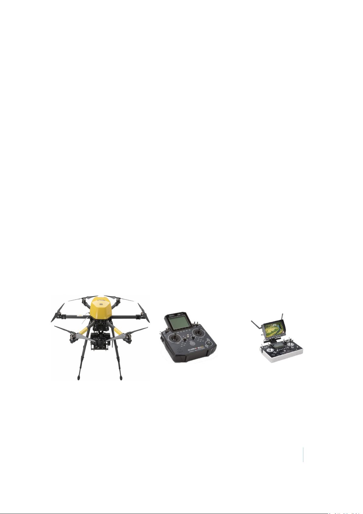
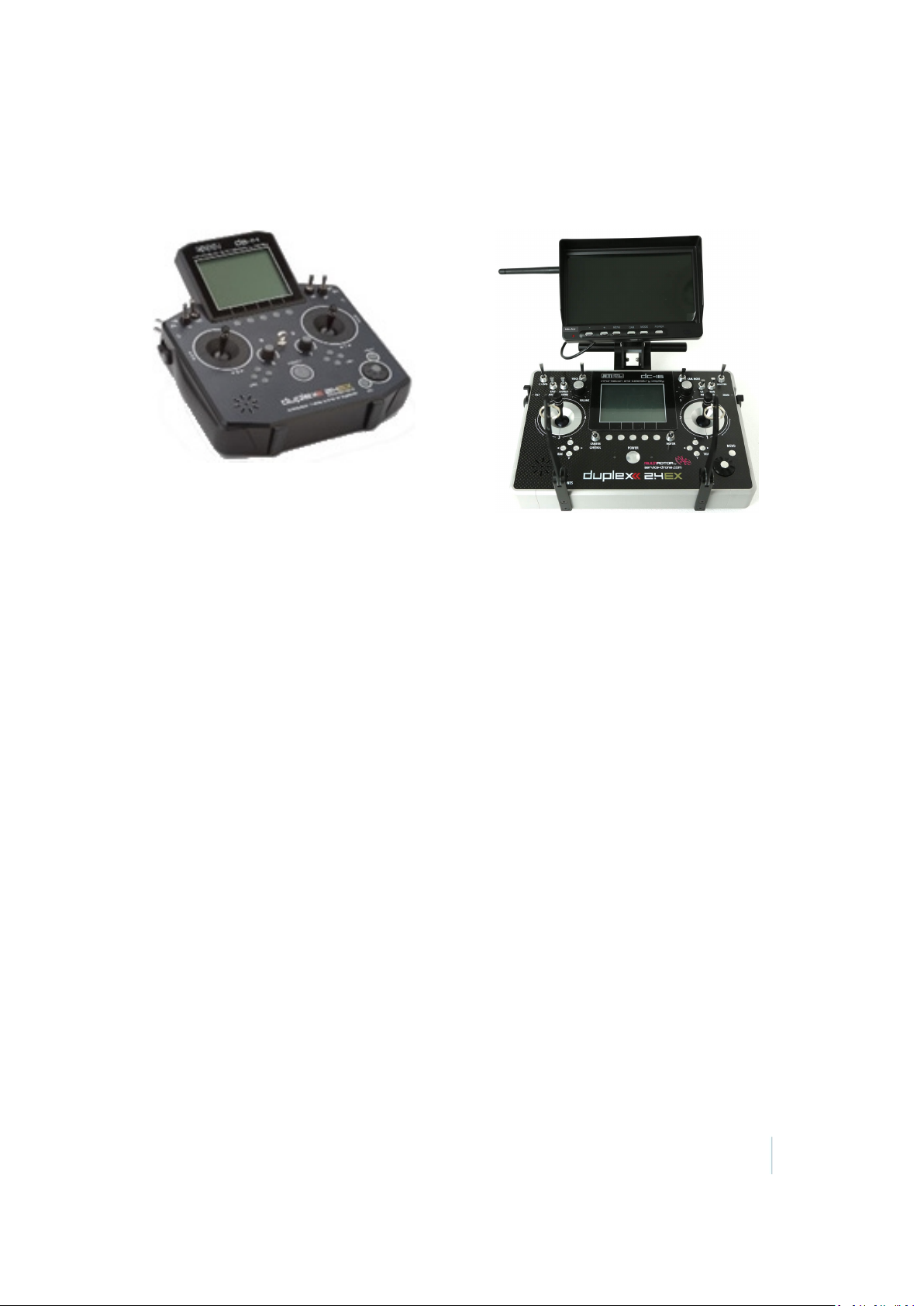
Ground control station
The ground control station is used to control the ZX5.
Jeti DS14 remote control Jeti DC16 remote control with the optional Inspection
Module
The remote control (RC) is linked to the ZX5 with a 2.4 GHz radio communication link. The RC
receives and shows telemetry data from the ZX5, analyzes the received telemetry data received
from the ZX5, shows the telemetry data on the RCscreen and, if required, sends audible messages
to the pilot about the state of the ZX5 components. In addition, the RCsends data (such as
geographical coordinates)and flight control instructions to the ZX5.
The remote control is powered by its own lithium polymer battery. The top right corner of the
remote control display shows the battery status. Charge the battery with the provided charging
device. For more information, refer to the manual provided with the radio control unit.
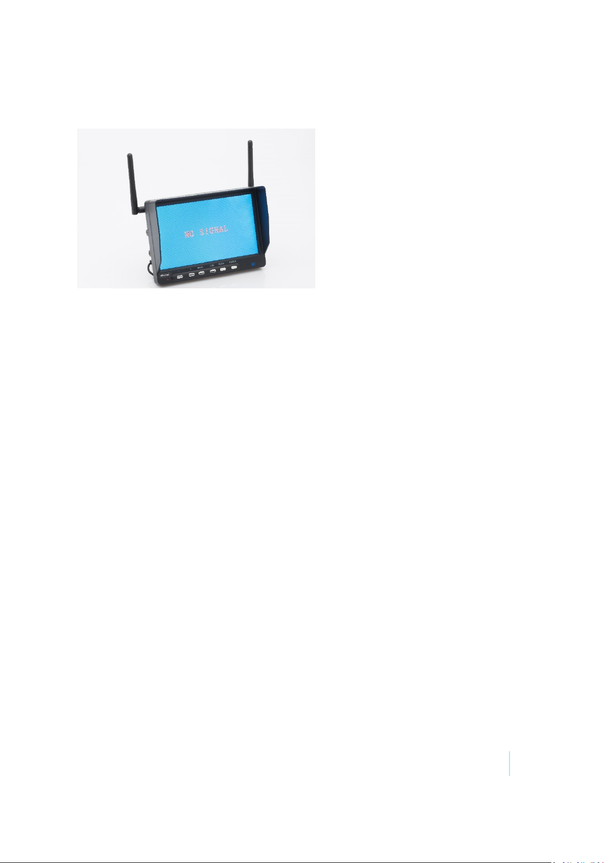
If you have purchased the Inspection Module, the ground control station includes a monitor with
video receiver. On the monitor the pilot can see the live view of the transported camera. The
monitor has its own lithium polymer battery, separate to the battery provided for the remote
control unit. Low battery status for the monitor is indicated by a red LED on the front of the
monitor.
The ZX5 can be controlled with the following models of remote control: Jeti DC16 or Jeti DS14. For
more information, see Operating the ZX5 Using the Remote Control .
Video receiver
This is available with the Inspection Module only.
The video receiver receives the video signal direct from the ZX5 and reproduces the picture on the
monitor. The monitor has its own lithium polymer battery, separate to the battery provided for the
remote control unit. Low battery status for the monitor is indicated by a red LED on the front of the
monitor.
Note – Use the same battery charger to charge the battery as for the ZX5 battery, but make sure
the charge current switch is set to 1 A.
Trimble ZX5 User Guide 17
Page 18
1 Introduction
To ensure safe operation and long battery life, refer to the general advice for all LiPo batteries as
described in this guide. If the battery voltage falls below 9.6V, replace the battery.
The complete video receiver package (receiver, monitor, battery) can be either fixed to the remote
control or onto a tripod. To display the picture, attach the battery and power on the monitor.
Trimble ZX5 User Guide 18
Page 19

Preparing Equipment
C H A P T E R
2
n Transportation
n Checking the ZX5 aerial imaging rover
n Checking the GCS
n Checking the ZX5 battery pack
n Charging the ZX5 battery pack
n Pre-flight acoustical signals
n Charging the camera batteries
n Configuring the camera settings
As part of your flight preparation, make sure all
equipment is in good condition and
well-prepared.
Trimble ZX5 User Guide 19
Page 20
2 Preparing Equipment
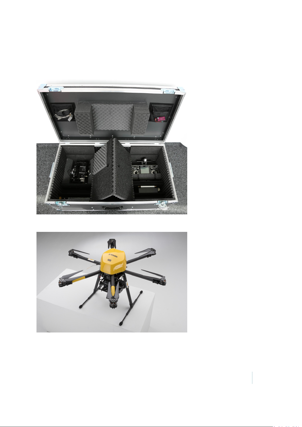
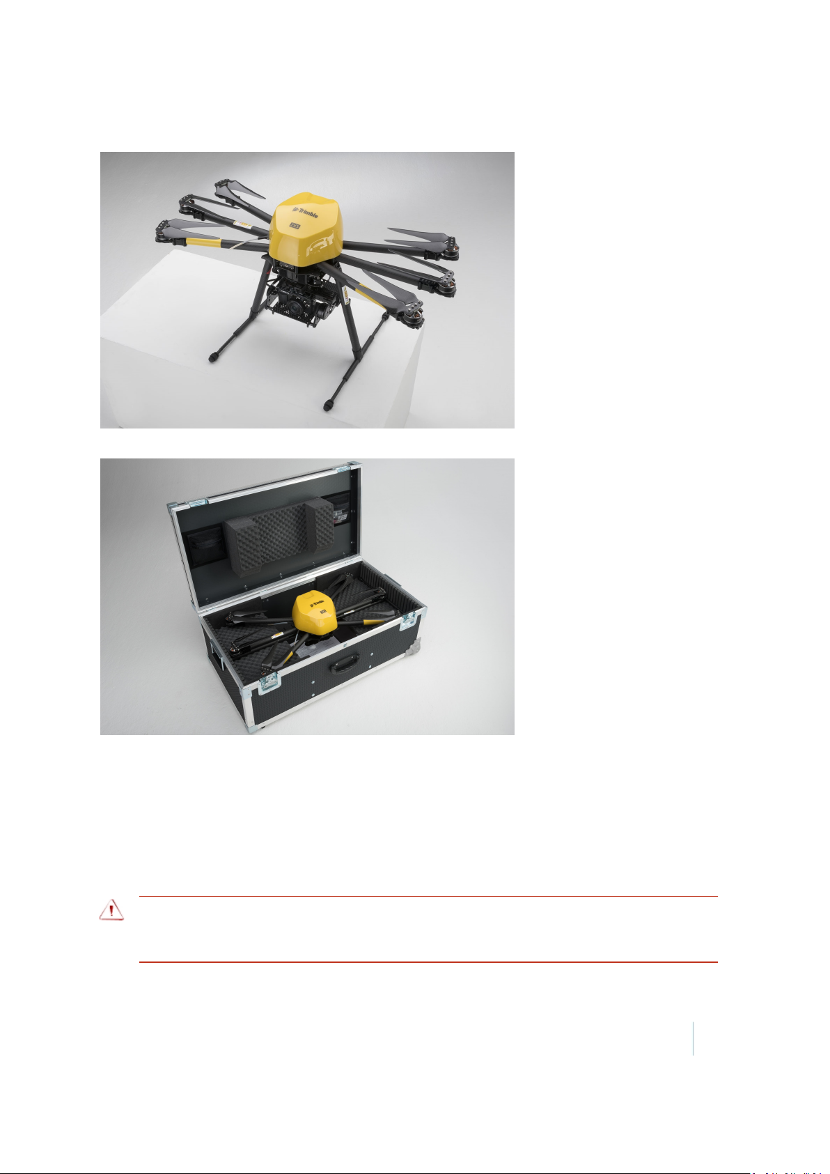
Transportation
When transporting the system, store the ground control station and the gimbal into the base of
the flight case:
Take special care not to damage the propellers on the ZX5. To avoid contact with any other objects,
fold the propellers as shown:
Trimble ZX5 User Guide 20
Page 21
2 Preparing Equipment
After folding the propellers, fold the arms of the ZX5 frame:
Store the folded frame in the top tray of the flight case:
Secure the equipment well in the vehicle. Check the equipment again each time you remove it from
the flight case.
Checking the ZX5 aerial imaging rover
Thoroughly check the ZX5 before each flight to make sure that it is undamaged from any previous
flight.
WARNING –Damage to parts can cause unstable flight characteristics, which may lead to loss of
control of the aircraft. If you find any damage, do not fly. Exchange the part or contact your Trimble
service provider.
Trimble ZX5 User Guide 21
Page 22

2 Preparing Equipment
Refer to the following sections:
l Check the frame, page 22
l Check the propellers, page 22
l Check the dome, page 23
Check the frame
1. Check all parts for cracks, abrasion, broken parts.
2. Visually make sure all bolted connections on the ZX5 fuselage, the six arms, and landing gear
are secure.
Note – All screws and nuts are either self locking or sealed with loctite.
3. Check the antennas and make sure they are correctly aligned and free of kinks. If required,
align the antennas in a straight line.
If any antenna has kinks, then signal transmission is limited. For more information, contact
your Trimble service provider.
4. Check the landing gear and make sure:
a. The legs snap in correctly.
b. During folding/unfolding of the landing gear there is a grinding resistance to avoid
flapping.
5. Check the six arms and make sure:
a. The arms snap in correctly.
b. During folding/unfolding of the arms there is a grinding resistance to avoid flapping.
6. Check the motors and turn them with your hand to make sure they move freely without
making any unusual grinding or bearing noise.
If a motor is difficult to turn or if you hear a grinding or bearing noise when turning it, contact
your Trimble service provider.
If you find any damage to any part of the frame, refer to the Trimble ZX5 Maintenance Guide.
Alternatively, contact your Trimble service provider.
Check the propellers
1. Clean the propellers carefully using a damp cloth.
2. Check the propellers for cracks, abrasions, or broken parts.
3. Make sure each propeller is freely moveable and unfolds easily. If the folding mechanism is
dirty, clean it carefully using a smooth brush or compressed air.
4. Make sure the propellers are fitted to the correct motor.
The clockwise rotating propellers must be installed on the clockwise rotating motors and the
counter-clockwise rotating propellers must be installed on the counter-clockwise rotating
motors.
Trimble ZX5 User Guide 22
Page 23
2 Preparing Equipment
5. If any propellers are damaged, cannot be cleaned, or are not correctly installed, replace them
immediately. For more information, refer to the Trimble ZX5 Maintenance Guide.
WARNING – Never fly with a damaged propeller. Always replace a damaged propeller before the next
flight. A damaged propeller can cause loss of control of the ZX5. Loss of control of the ZX5 may lead to
a crash, resulting in equipment damage, property damage, or personal injury.
WARNING –Dirt on the propellers can disturb the balance and cause unnecessary vibration. Vibration
can cause blurred and out of focus images or affect the flight characteristics of the ZX5, causing
damage to the ZX5 or loss of control.
WARNING – If one or more propellers are fitted to a motor that rotates in the opposite direction to
the propeller, the ZX5 cannot fly correctly. It cannot be operated by the pilot, flips upside down and
will be damaged. An uncontrolled ZX5 can also cause serious personal injury.
Check the dome
WARNING – Always disconnect the battery pack before removing the top cover.
1. Make sure all wire connections inside and outside the dome are clean and free of damage.
Clean any dirty connections with a smooth brush.
2. Make sure all connectors and soldered wires are fitted correctly.
3. When removing the top cover, make sure there is a grinding resistance.
If you find any damage, contact your Trimble service provider.
Trimble ZX5 User Guide 23
Page 24

2 Preparing Equipment
Checking the GCS
Thoroughly check the GCS before each flight to make sure that it is undamaged from any previous
flight.
WARNING –Damage to parts can cause unstable flight characteristics, which may lead to loss of
control of the aircraft. If you find any damage, do not fly. Exchange the part or contact your Trimble
service provider.
1. Check all parts for cracks, abrasion, broken parts.
If you find any damage, refer to the Trimble ZX5 Maintenance Guide.
2. Check all bolted connections.
If you find any damage, refer to the Trimble ZX5 Maintenance Guide.
3. Check all wire connections and make sure they are clean and free of damage. Clean any dirty
connections with a smooth brush.
If you find any damage, contact your Trimble service provider.
4. Check the antennas and make sure they are correctly aligned and free of kinks.
If any antenna has kinks, then signal transmission is limited. For more information, contact
your Trimble service provider.
Checking the ZX5 battery pack
Thoroughly check the ZX5 battery pack before each flight to make sure that it is undamaged.
WARNING –Do not charge or use a damaged battery. Damage to the battery can cause fire or the
emission of hazardous vapors when the battery is being charged or is in use.
1. Check the battery for pressure marks, cuts, cracks, swelling and any deformities.
2. Make sure the isolation on the battery is completely intact.
3. If the battery has been in a crash, take special care when charging the battery as although
there may be no external signs of damage, it may have sustained internal damage.
If the battery balloons or expands, it cannot be used again and must be disposed of safely.
Charging the ZX5 battery pack
Carefully read this section to familiarize yourself with charging and storing ZX5 batteries.
Always recharge the batteries before use.
WARNING –Lithium polymer batteries are volatile. Make sure to read and understand all information
regarding battery charging and use in this document and the Trimble ZX5 Lithium Polymer Battery
Precautions guide.
Trimble ZX5 User Guide 24
Page 25

2 Preparing Equipment
CAUTION –Do not separate the battery pack. Always use the complete battery pack for the lifetime of
the poorest battery. Attempting to separate the battery pack will damage the batteries.
In this section:
l Charger overview, page 25
l Removing the battery from the rover, page 25
l Connecting the charger, page 26
l Charging the battery, page 28
l Disconnecting the charger, page 28
l Inserting the battery pack into the ZX5, page 29
l Storing the battery, page 29
Charger overview
Removing the battery from the rover
1. Disconnect the main power connectors of the batteries from the rover.
2. Loosen the Velcro straps and remove the batteries from the battery compartment of the ZX5.
Trimble ZX5 User Guide 25
Page 26

2 Preparing Equipment
Connecting the charger
WARNING –Lithium polymer batteries are volatile. Failure to read and follow these instructions may
result in fire, personal injury, and damage to property if charged or used incorrectly.
To prevent injury or damage:
– Use only the charger specified to charge the battery pack.
– Use the charger to charge only ZX5 battery pack.
– Do not use or charge a battery pack if the battery pack, charger or charging cables appear damaged.
– Always check that the settings on the charger are correct before charging the battery. Incorrect
charger settings may result in damage to the battery, severe burning and fire hazards.
– Always remove the battery pack from the ZX5 body for charging or storing.
– Do not attempt to recharge the battery if it is still fully charged.
– Do not recharge the battery directly after use. Always wait until the batteries have cooled down first.
WARNING – Never connect the battery power adapter cable to the battery without first connecting
the adapter cable to the charger. Connecting the adapter cable to the battery risks short-circuiting the
battery, which may result in fire, personal injury, or damage to property.
CAUTION –Always connect the balancer cable to the battery before charging. Failure to connect the
balancer cable can cause the lithium polymer cells to overload, damaging the battery.
1. If the battery pack is fitted in the ZX5, remove the battery pack from the ZX5 body.
2. Connect the battery power adapter cable to the charger. Insert the red connector into the red
socket and the black connector into the black socket:
Trimble ZX5 User Guide 26
Page 27

2 Preparing Equipment
3. Connect the balancer cable adapter to the charger:
4. Connect the power cable adapter to the power connector of the battery and connect the
balancer cable to the 4s socket of the battery:
5. Make sure the switches are set to the correct position on the charger. They should be:
l Battery type:LiPo
l Charge current: 5 A for the ZX5 battery; 1 A for the video receiver battery.
Trimble ZX5 User Guide 27
Page 28

2 Preparing Equipment
6. Connect the AC power cable to the socket on the charger.
Charging the battery
WARNING – Never leave the charger unattended during use and do not leave a battery to charge
overnight. Place the battery on a fireproof base during charging and remove highly combustible
materials from around the battery. Failure to observe and operate the charger properly can cause
damage to the charger, battery, personal property and/or cause serious personal injury.
WARNING – If at any time you observe the battery swelling or ballooning while charging, immediately
disconnect the charger and observe the battery carefully in a safe place away from flammable
materials. If the battery balloons or expands, it cannot be used again and must be disposed of safely.
WARNING – Allow the charger and the battery to reach room temperature before connecting the
charger to mains power and using it. This may take several hours.
1. Set up the battery and charger on a non-flammable surface, away from flammable materials
and other objects.
2. Make sure the battery is connected to the charger correctly.
3. Connect the AC power cable to a mains power socket.
The battery status LED lights red and charging starts.
When the battery is fully charged, the battery status LED lights up green.
At typical room temperature it takes approximately 2 hours to charge the battery. Charging a fully
discharged battery can take up to 3 hours. Charging time will vary depending on remaining battery
life and ambient temperature.
The battery voltage should always be between 12.8 V and 16.8 V.
Disconnecting the charger
1. Disconnect the AC power cable from the power source and the charger.
2. Disconnect the power cable from the power connector of the battery.
3. Disconnect the balancer cable from the 4s socket of the battery.
Trimble ZX5 User Guide 28
Page 29

2 Preparing Equipment
4. If you have not yet charged both batteries, connect the second battery and charge it using
steps 4 through 6 in the section "Connecting the charger" above.
Inserting the battery pack into the ZX5
WARNING – Always fully charge the batteries before each flight. Only insert fully charged batteries
into the ZX5. Using partially charged batteries will significantly reduce the flight time.
Note – In low outdoor temperatures (less than 10°C / 50°F) the battery capacity reduces itself
down to about 50 %. When using the ZX5 in such temperatures, keep the ZX5 and the batteries in
a warm environment for as long as possible before the flight.
1. Insert the battery pack into the battery cavity above the camera gimbal at the rear of the
ZX5and then tighten the Velcro straps around it.
2. Connect the main power connectors of the batteries to the rover.
CAUTION –Do not separate the battery pack. Always use the complete battery pack for the lifetime of
the poorest battery. Attempting to separate the battery pack will damage the batteries.
Storing the battery
WARNING – LiPo batteries should never be stored at full charge for more than a few hours.
Note – The charger can only charge a battery; it cannot discharge a battery. Stored batteries
should be recharged every three months.
Battery storage recommendations
Store the ZX5 batteries in a cool, dry area (below 15–20°C/59–68°F) that is subject to little
temperature change. Elevated temperatures can result in reduced battery service life.
Do not place batteries near heating equipment, nor expose to direct sunlight for long periods.
Trimble ZX5 User Guide 29
Page 30

2 Preparing Equipment
Do not store batteries above 60°C (140°F) or below 10°C (50°F). Battery exposure to temperatures
in excess of 130°C (266°F) will result in the battery venting flammable liquid and gases.
Batteries should be separated from other materials and stored in a noncombustible, well
ventilated, sprinkler-protected structure with sufficient clearance between walls and battery stacks.
Pre-flight acoustical signals
A signal transmitter located on the frame of the ZX5 provides audible signals to report different
conditions:
Signal pattern Signal description Meaning
_ __ _ _ 1 short beep, 1 long
beep, 2 short beeps
_________ 1 continuous beep Warning: SD card or GPS not connected
_ _ _ 3 short beeps Warning: Can't receive remote control signal
__ _ _ _ _ 1 long beep, 4 short
beeps
__ __ _ _ _ 2 long beeps, 3 short
beeps
__ __ _ _ _ 2 long beeps, 3 short
beeps
In addition, the motors buzz after powering up the system.
Other signals could also indicate malfunction. If you hear unusual signals, do not perform any
further flights. Check the MX menu for the latest error message and contact Trimble for more
information.
Note – If there is an acoustic signal for low battery voltage during the flight, you cannot start the
motors again after landing until you have disconnected the battery.
Voice announcements from the remote control unit indicate status information during flight. For
more information, see Remote control in-flight announcements, page 45.
Everything OK
ZX5 does not stand straight
Malfunction: Motor switch is activated without
minimum throttle or Coming Home mode is still active.
ZX5 is disabled: register with Trimble.
Charging the camera batteries
Install the camera battery and charge the batteries according to the instructions provided in the
user documentation for the camera.
Note – Make sure you charge both camera batteries before leaving the office for a flight. Trimble
recommends always having a spare, fully-charged battery on hand.
Trimble ZX5 User Guide 30
Page 31

2 Preparing Equipment
Configuring the camera settings
Refer to the documentation provided with the camera for camera operation instructions. However,
to obtain good aerial images using the Olympus E-PL7 camera, Trimble recommends changing the
camera settings to the following:
1. Set the Mode dial to M (manual mode).
2. Press the Menu button, select the Setup menu and do the following:
a. Set the correct date and time (Trimble recommends using UTC format).
b. Set Rec View to Off.
c. Set Wi-Fi to Off.
d. Make sure Menu Display is set to On, so that you can view custom menus.
3. Navigate to the Custom menu and do the following:
a. Select AF/MF and then set MF Assist / Magnify to Off and Reset Lens to On. This resets
the lens to focus on infinity each time the camera is turned on.
b.
Select and then set the ISO-Auto Set / High Limit to 1600.
c.
Select and then set the Sleep option to Off.
4. If you do not want to manually have to press the shutter switch on the remote control unit to
capture photographs, you can set photos to be captured at regular intervals. To do this,
navigate to Shooting menu 2 and select Time Lapse Settings.
You can set an interval of photos, for example 30 pictures every 2 seconds. You can trigger the
interval with the shutter on the remote control. The interval can be restarted using the remote
control shutter switch as soon as the previous interval is finished or if the number of photos
which are set for the interval is high enough, then you will need to trigger the interval using the
shutter switch only once per flight.
5. Exit the Menu screens to return to Shooting mode. Press the OK button to view the
information display and use the control panel to set the following:
a. Set the Image stabilizer option to Off.
b. Set the Image quality option to LF.
c. Set the Flash mode to Fill-in flash.
d. Set the Brightness (metering) to ESP.
e. Set the Focus mode to MF (manual).
Note – Setting focus to manual and using a large depth of field gives better results than
using auto focus. Resetting the lens to focus on infinity (step 3a above) and using the
recommended ISOsettings (below) gives a large depth of field.
f. Set the ISO settings to a minimum shutter speed of 1/500 with an f-stop value at 5.6
(minimum 4.0).
g. Set the Face priority mode to Off.
Trimble ZX5 User Guide 31
Page 32

C H A P T E R
3
Operating the ZX5 Using the Remote Control
n Controls on the remote control unit
n Main functions
n Camera functions
n Additional functions
n Flight functions
n Remote control software menus
n Remote control in-flight
announcements
Before completing your first flight, make sure to
familiarize yourself with the topics in this section
of the user guide.
Trimble ZX5 User Guide 32
Page 33

3 Operating the ZX5 Using the R emote Control
Controls on the remote control unit
The ZX5 comes with one of the following remote control units:
l DC-16 remote control
l DS-14 remote control
Make sure to familiarize yourself with the function and position of all controls on the remote
control unit before flying the ZX5 for the first time.
DC-16 remote control
Trimble ZX5 User Guide 33
Page 34

3 Operating the ZX5 Using the R emote Control
DS-14 remote control
Main functions
Control Use
RCPower Power on/power off of the RC
Press the power button and confirm it with Yes on the menu bar.
Motors Motor start
Pull the throttle stick completely back while simultaneously moving the motor
switch up to the top.
Note – The motor switch is a safety-lock-switch. Pull the switch up to move it.
Motor stop
Pull the throttle stick completely back while simultaneously moving the motor
switch down.
Note – This is a safety-lock-switch. Pull the switch up to move it.
Throttle
(left stick)
ZX5 ascent/descent
The ZX5 keeps the flying height autonomously, if the throttle stick is in the
Trimble ZX5 User Guide 34
Page 35

3 Operating the ZX5 Using the R emote Control
Control Use
middle position. When the throttle stick is pushed forward the ZX5 ascends,
when it is pulled to the back the ZX5 descends.
Camera functions
Control Use
Campitch Camera mount pitches (Available with the Inspection Module only)
2.Level To activate the second function of the sticks
Pull the 2. Level stick and keep hold. Now move the other sticks:
Left stick left/right: Camera mount rolls
Right stick forward/backward: Camera mount pitches
Trigger Camera trigger
Pull the switch to take a photo or start/stop the video.
Zoom Camera zoom
Note – This function does not apply to the Olympus E-PL7 camera.
CamModus Camera start/stop for different cameras
If you have several different camera integrations, this switch is used for
starting/stopping the second or third camera.
Cameracontrol Selector switch for camera control by the pilot or the cameraman
If you are using a separate cameraman remote control, you can select if the
pilot (switch up) or the cameraman (switch down) has control of the camera
features.
Additional functions
Control Use
Voice Reads out the telemetry data shown on the display
Volume Changes the volume of the voice outp20
Trimble ZX5 User Guide 35
Page 36

3 Operating the ZX5 Using the R emote Control
Flight functions
The ZX5 comes with different flight functions. It is possible to fly it using full manual control or fully
automatically.
Depending on the remote control unit you are using, different flight functions are available:
l Standard flight functions (DC-16 and DS-14 remote control)
l Flight modes for the DC-16 remote control
Note – Some GPS functions refer to the "starting point". The starting point is usually the takeoff
position. However, if you start the ZX5 and take off before it has time to identify the GPS position,
then the starting position is the first-fix position, which is the point during the flight where the
where the ZX5 can first identify its GPS position.
Standard flight functions (DC-16 and DS-14 remote control)
To operate the ZX5, use the following flight functions on the remote control unit:
Auto start
Automatic start function to facilitate take off.
Requirement: The ZX5 must be on the ground with the motors idling.
Activation: Move the Launch/Landing or Start/Landing switch to the Launch or Start position.
Performance: The ZX5 starts and ascends approximately 2m (6.5ft).
Auto landing
Automatic landing function to facilitate landing.
Requirement: The ZX5 is flying. If the ZX5 is over 10m (33ft) high it descends faster; below 10m
(33ft) the descent is slower.
CAUTION –Only activate Auto landing when the ZX5 is flying with the camera fitted, as flying without
the camera installed changes the center of gravity of the ZX5. Activation of Auto landing without the
camera installed may lead to a crash.
CAUTION –On hilly ground the chosen landing place may be 10 m higher than the starting position. In
this situation the ZX5 may descend too fast and touch ground with too much speed, which can cause
damage. If you think the landing place may be higher than the starting position, land manually.
WARNING –Always pay close attention to the ZX5 when Auto landing is activated, in case you need to
manually intervene.
Activation: Move the Launch/Landing or Start/Landing switch to the Landing position.
Trimble ZX5 User Guide 36
Page 37

3 Operating the ZX5 Using the R emote Control
Performance: The ZX5 lands automatically.
The motors reduce speed to idle and may appear to have stopped. However, the ZX5 is still turned
on. To avoid injury, you should immediately manually power off the ZX5 by pulling the throttle
stick completely back while simultaneously pulling the motor switch up to move it and then moving
the motor switch down to the motor stop position.
Note – At the moment of touchdown, there should be no sideways movement otherwise the ZX5
can overturn. To eliminate this, manually keep the ZX5 in position to compensate for inaccuracies
in the GPSposition.
WARNING – For safety reasons, after landing the motor speed can increase again after 2seconds
under certain circumstances. To avoid incremental movement caused by inaccuracies in the
GPSposition, immediately shut down the ZX5 motors completely, even if you intend to restart the ZX5.
To do this, pull the throttle stick on the remote control all the way down and move the motor switch to
the Off position. Attempting to restart the ZX5 when the motors are idling can cause loss of control of
the ZX5 and lead to a crash directly after take-off.
Cancellation: To cancel landing, slightly move the left stick.
Go Ahead
Automatic alignment function.
Use this function if the pilot does not remember or cannot see the direction the ZX5 is aligned. The
Go Ahead function turns the ZX5 once only so that the starting point is behind it. This means that
the right-stick-steering conforms to the resulting movement of the ZX5 as long as it is not yawed by
the pilot.
Requirement: The ZX5 is flying and is at least 20m (65ft) away from the starting point.
Activation: Move the Easy/Ahead switch to the Ahead position.
Performance: The ZX5 turns in flight on the spot so that the starting point is behind it.
Easy Move
Extended automatic alignment function.
This function helps the pilot to manoeuvre the ZX5 more easily. To keep the steering more intuitive,
the alignment of the ZX5 is no longer considered during conversion of the steering commands. This
means that the ZX5 always flies in the direction in which the right stick is shifted regardless of where
the ZX5 is located. The imaginary line between the starting point and the ZX5 equals the stick axis
(forward – backward) of the right stick.
Requirement: The ZX5 is flying and is at least 20m (65ft) away from the starting point.
Activation: Move the Easy/Ahead switch to the Easy position.
Behavior outside the 20m (65ft) radius: From the view of the pilot, the ZX5 always moves
analogous to the movement of the right stick regardless of the position the ZX5 is directed.
Example 1 — Right stick to the front: the ZX5 always flies straight away from the
starting point.
Example 2 — Right stick to the back: the ZX5 always flies straight towards the starting
point.
Trimble ZX5 User Guide 37
Page 38

3 Operating the ZX5 Using the R emote Control
Example 3 — Right stick to the right: the ZX5 flies spirally around the starting point.
Behavior inside the 20m (65ft) radius: Inside the 20m radius the ZX5 behaves slightly differently
to avoid the problems of the GPS inaccuracy. The directing of the ZX5 stays the same as it was on
the point of activation.
The following examples describe the behavior of the ZX5 when the Easy Move function is activated
inside the 20m radius, while the ZX5 is directed to the NW(45°):
Example 4 — Right stick pushed forward: the ZX5 flies toward the NW. After passing
the 20m radius it carries on flying in this direction, because it behaves as described in
example1.
Example 5 — Right stick pulled backward: the ZX5 flies toward the SE(225°/-135°).
After passing the 20m radius it changes direction and flies backward towards the
starting point as described in example2.
Example 6 — Right stick to the right: the ZX5 flies toward the SW(135°). After passing
the 20m radius it changes direction and flies spirally around the starting point as
described in example3.
Behavior while entering the 20m (65ft) radius: When the ZX5 is flying into the 20m radius, the
current orientation is fixed so that the ZX5 does not change direction while entering the 20m radius
if the right stick is held continuously.
Behavior while exiting the 20m (65ft) radius: When the ZX5 is flying out of the 20m radius, the
front is at the end of an imaginary line from the starting point to the ZX5. If applicable the ZX5
changes direction.
Flight modes for the DC-16 remote control
Note – The DC-16 remote control is available with the Inspection Module only.
Each flight mode is described below, starting with the lowest automatic level.
WARNING – The MAG/ALT switch on the remote control unit must be in the upper position at all
times. By default, this switch is disabled but if used incorrectly it may confuse the system and cause
loss of control of the ZX5. Failure to control the ZX5 can lead to a crash, resulting in equipment
damage, property damage, or personal injury.
WARNING – The pilot experience level for each flight mode is given below. Make sure you use only
the flight modes for which you have the appropriate level of experience. Flight modes suitable for
advanced pilots require advanced skills such as navigating against wind to avoid loss of control of the
ZX5. Failure to control the ZX5 can lead to a crash, resulting in equipment damage, property damage,
or personal injury.
WARNING – GPS functions are turned off automatically if the satellite receiving power drops below 6
satellites or the position accuracy rises above 8m (26ft). This may be due to, for example, satellite
issues, atmospheric disturbance or signal interference from other radio sources. In this situation, the
ZX5 reverts to Manual flight mode.
Trimble ZX5 User Guide 38
Page 39

3 Operating the ZX5 Using the R emote Control
Manual flight
Flying without GPS functions.
In this mode the dynamic flight characteristics of the ZX5 can be fully used. The altitude and
direction are maintained automatically by magnetic field sensor (compass).
Activation: Move the CH/PH switch to the Manual Flight (backward) position.
Performance: In this mode all GPS functions are deactivated.
Pilot experience level: This flight mode is suitable for advanced pilots only. In windy situations the
ZX5 can be pushed away and rotated, unless the pilot navigates against it. Using this mode without
the appropriate level of experience can cause loss of control, leading to a crash.
GPS Position Hold
Automatic position stabilization by GPS.
In this mode the movement of the ZX5 is controlled by GPS. Speed is limited, and the rate of
acceleration and deceleration is lowered. If hovering in one position, the position is held
automatically. In flight the flight direction is maintained. The ZX5 also automatically compensates
for wind.
Activation: Move the CH/PH switch to the GPS Position Hold (middle) position.
Performance: The ZX5 maintains its position and direction even in windy situations.
Note – If a problem occurs during the flight and the ZX5 is unable to hold its GPS Position, for
example a propeller is damaged, then deactivate the GPS function and switch to Manual flight
mode to safely land the ZX5.
GPS Coming Home
Automatic return flight to the starting position.
Use this mode if the pilot loses orientation or if the mission is completed and the ZX5 should come
back to the starting position to land.
WARNING – In Coming Home mode, the ZX5 always takes the shortest, most direct way back to the
starting point. Make sure the ZX5 is flying at an appropriate altitude, with no obstacles, before
activating this mode.
WARNING –Always pay close attention to the ZX5 when Coming Home is activated, in case you need
to manually intervene. To cancel the Coming Home function, lightly move either the left or right stick.
The ZX5 changes to GPS Position Hold mode.
Activation: Move the CH/PH switch to the GPS Coming Home (upper) position.
Performance: The ZX5 flies back to the starting position.
Cancellation: This function can be canceled by slightly moving either the left or the right stick. The
ZX5 changes to GPS Position Hold mode.
Trimble ZX5 User Guide 39
Page 40

3 Operating the ZX5 Using the R emote Control
Remote control software menus
Use the software on the remote control unit to view information about the connected ZX5.
The first three menu screens show the current telemetry data of the ZX5. Use the Extended Menu
to make adjustments to the flight path, and view information about the connected ZX5.
Use menu buttons 1 – 5 to navigate the software menus.
Telemetry data
Telemetry data is shown on the first three pages, which you can page through using menu buttons
2 and 3.
Telemetry data page 1
Field Description
Voltage Voltage value of the ZX5 batteries.
If the voltage drops below 14.0 V, an audible
message warns "Warning, low battery".
Capacity Spent battery capacity of the ZX5 batteries.
Compass Compass alignment of the ZX5:
0° = N
90° = O
180° = S
-90° = W
Altitude Height related to the starting point.
Distance Horizontal distance.
Flight
Time
Flight time since motor start <hh:mm:ss>.
Telemetry data page 2
Field Description
Latitude Geographical latitude of the current GPS
position.
Longitude Geographical longitude of the current GPS
position.
Satellites Number of the current receiving satellites.
The more satellites, the better the accuracy of
the position.
GPS Fix Quality of the specified position:
Trimble ZX5 User Guide 40
Page 41

3 Operating the ZX5 Using the R emote Control
Field Description
0D – No satellites,
1D – Up to 4 satellites
3D – 5 or more satellites
Note – To use GPS mode, the ZX5 requires at
least 3D fix.
Position
Acc
Speed Acc Accuracy of speed.
Accuracy of position.
A lower value means better accuracy of GPS
functions.
A lower value means better accuracy of GPS
functions.
Telemetry data page 3
Field Description
Speed Current flying speed.
Current The current being used by the ZX5.
Temperature Surrounding temperature in the ZX5.
Telemetry data page 4
Page 4 of the menu screens provides access to the Jetibox menu, which enables you to modify the
parameters of the Jetibox radio receiver. Normally there is no need to change these parameters.
For more information, refer to the documentation provided with the Jeti remote control.
From page 4 of the menu screens you can also access the extended menu for the ZX5. To do this:
1. Press the Menu changeover switch (ESC button).
Trimble ZX5 User Guide 41
Page 42

3 Operating the ZX5 Using the R emote Control
2. Press menu button 2 to view the MX page.
3. Press menu button 3 to view the extended menu.
Extended menu
The Extended menu enables you to:
l Activate extended functions
l Set the parameters
l Calibrate the sensors
l Check the problem report
l View information about the ZX5
Note – For changes to the settings to take effect, the ZX5 must be powered on and connected to
the remote control.
A diagram of the Extended menu functions is shown below.
Trimble ZX5 User Guide 42
Page 43

3 Operating the ZX5 Using the R emote Control
Trimble ZX5 User Guide 43
Page 44

3 Operating the ZX5 Using the R emote Control
The table below explains how to use the Extended menu:
Menu item Sub-menu
Description
item
Functions POI
Coordinates
Define the GPS coordinates and the height above the starting point
for a point of interest (POI). Once the POI function is activated, the
ZX5 aims for the defined point.
POI Mode Activate and deactivate the POI function.
Settings Select Config Always use configuration 1.
Magnetic
declination
Enter the correct magnetic declination value of your location.
To calculate the correction value for the latest interpretation of the
magnetic field for your scheduled location, go to
www.ngdc.noaa.gov/geomag-web/#declination.
WARNING –
not work correctly.
GPS Speed
manual
GPS Speed
auto
If the magnetic declination is set incorrectly, the ZX5 GPS functions will
View and change the maximum speed when GPS is enabled (GPS
Position Hold flight mode).
View and change the maximum speed in automatic flight modes (for
example, GPS Coming Home).
Altitude Limit View and change the maximum altitude.
Note – Before changing the altitude settings, make sure you are
familiar with the appropriate regulations for the country you are
operating in and that any changes you make comply with those
settings.
Calibration Gyro offset The ZX5 gyro sensors are calibrated on delivery.
Do not change any settings without consulting Trimble.
Acc offset The ZX5 acceleration sensors are calibrated on delivery.
Do not change any settings without consulting Trimble.
Compass Trimble recommends recalibrating the compass, along with setting
the magnetic declination, before your first flight. For information on
performing this procedure, see Calibrating the compass, page 58.
Infos
Errors
(Number of
incidents)
WARNING –
calibrated, the ZX5 cannot fly correctly.
Battery low Battery voltage falls below 13.2 V during flight.
If the gyro offset, acceleration sensors, or compass are incorrectly
This can occur if the flight was too long or the battery was strained.
If this error occurs regularly, you should perform shorter flights or
replace the battery pack.
Radio control Radio contact was temporarily lost during the last flight.
Trimble ZX5 User Guide 44
Page 45

3 Operating the ZX5 Using the R emote Control
Menu item Sub-menu
item
I2C0 Internal error.
GPS time out The GPSreceiver delivers no
Magnetometer The magnetometer sends
ADC The analog digital converter
Main overrun Internal error.
SPI1 overrun Internal error.
Spurious ISR Internal error.
Stack overflow Internal error.
Infos
Drone
Config page Current configuration set. This should always show configuration 1.
Model number Shows the model number of the ZX5.
Serial number Shows the serial number of the ZX5.
Description
This can occur if obstacles block the radio signal between the
remote control unit and the ZX5 during flight.
data.
incorrect data.
If any of these errors occur,
sends incorrect data.
please contract Trimble Support.
Motor position Shows the current motor configuration of the ZX5.
Features Shows the GPS functions purchased for the ZX5.
GPS Rx version Shows the version number of the GPS receiver firmware installed on
the ZX5
Flight counter Shows the number of flights completed by the ZX5.
Flight time Shows the overall flight time for the ZX5.
Software
MCU1
Software
MCU2
Shows the version number of the MCU1 processor in the ZX5.
Shows the version number of the MCU2 processor in the ZX5.
Remote control in-flight announcements
Some conditions and events are announced via voice output. If there is a lot of noise around you,
you can use earphones to understand better. The radio control provides a 3.5 mm connection.
After connecting the ZX5 batteries, each motor beeps, and the current flight mode is announced.
For more information, see Pre-flight acoustical signals, page 30.
Trimble ZX5 User Guide 45
Page 46

3 Operating the ZX5 Using the R emote Control
During the flight the following further announcements may occur:
Announcement Action following the announcement
GPS OK GPS satellite reception is very good. The GPS functions can be used.
GPS control Position Hold flight mode is activated. The ZX5 maintains its position
automatically.
Coming home Coming Home function is activated. The ZX5 flies back to the starting point.
Easy Move
Easy Move mode is activated.
Mode
Set rear
Go Ahead function is activated. The ZX5 aligns itself once.
orientation
POI Mode POI mode is activated.
Waypoint Waypoint mode is activated.
Auto start The ZX5 starts automatically.
Auto landing The ZX5 lands automatically.
Attention:
Emergency
The ZX5 conducts an emergency landing. The pilot is able to readjust the
position and height.
landing
Warning: No
There is no SD card (flight recorder) inserted.
flight recorder
Warning: No
GPS
GPS functions are deactivated, due to very bad GPSsatellite reception.
The ZX5 now flies in manual mode, requiring the pilot to hold the position of the
ZX5.
Warning: Low
battery
Battery voltage is reaching minimum level. Pay attention to the voltage and
make sure to land the ZX5 before it reaches a voltage of 3.5 V per cell (equivalent
to 14.0 V per battery).
Trimble ZX5 User Guide 46
Page 47

Completing a Flight
C H A P T E R
4
n Checking flight permissions and
conditions
n Flight time
n Pre-flight checks
n Emergency failsafe functions
n Ending the flight
This chapter describes the tasks required in the
field to complete a successful flight with good
image data.
Trimble ZX5 User Guide 47
Page 48

4 Completing a Flight
Checking flight permissions and conditions
In the days before the flight, complete the following checks to make sure the flight can proceed.
Note – The use of unmanned aircraft in any national airspace system is regulated by the
applicable National Aviation Authority. The regulations for flying unmanned aircraft are subject to
change, sometimes without warning. It is the user’s responsibility to know and adhere to the
current laws for operating in the national airspace system. Trimble is not obliged to inform users
of changes to unmanned aircraft laws.
Trimble and Authorized Distribution Partners provide comprehensive training for the unmanned
aircraft system which includes recommended procedures to ensure the safety for the remote crew
members as well as the surrounding environment. It is the user’s responsibility to ensure safe
operations and adhere to safety and security measures required by the National Aviation
Authority. Trimble is not responsible for ensuring safe and secure operation of unmanned aircraft
by the user.
Checking flight permission
l Check if you need a permit to operate an unmanned aircraft in the airspace above the site.
l Make sure you understand the legal context for safe operation of an unmanned aircraft.
l Check for existing rules and standards with your local Civil Aviation Authorities (CAA).
l Make sure you have permission from the landowner.
l Make sure you have all other relevant permissions required for photography flights using
unmanned aircraft. In some countries you need permission from defense organizations, the
police, or a national geography institute to take pictures.
Checking weather
l In the days before the flight, check the TV weather broadcast or weather websites. This gives
you a good general idea of the weather for the next three to four days.
l For more accurate weather forecasts, consult and interpret aviation weather data through
various weather websites. You can also contact the national meteorological office or a local
meteorology office at an airport nearby.
l On the day of the flight, consult the Terminal Aerodrome Forecast (TAF) and METAR reports.
These are meteorological reports used in aviation.
l Make sure the weather conditions are within the operating limitations. See Operation
limitations, page 61.
Trimble ZX5 User Guide 48
Page 49

4 Completing a Flight
Bft km/h m/s kn SM
1 1-5 0.3-1.5 1-3 1-3
2 6-11 1.6-3.3 4-6 4-7
3 12-19 3.4-5.4 7-10 8-12
4 20-28 5.5-7.9 11-16 13-18
5 29-38 8.0-10.7 17-21 19-24
6 39-49 10.8-13.8 22-27 25-31
7 50-61 13.9-17.1 28-33 32-38
The table below shows the wind speed expressed in different units:
Operation limitations
The ZX5 cannot safely fly in all weather conditions. The acceptable range for different conditions is
shown below.
Note – Your country of operation may have different or additional operational requirements.
Make sure you are familiar with the appropriate regulations for the country you are operating in.
If you are flying in the United States see also FAA conditions and limitations of operation, page 66.
CAUTION – If any condition does not meet the acceptable range stated, the operator should abort the
flight. Flying outside the acceptable range of conditions will void your Trimble warranty. Trimble does
not guarantee good picture quality when flying in conditions beyond these limits.
Condition Limit
Endurance 20 minutes
Flight time without payload 25 minutes
Maximum operational ceiling 3,000 m (9,843 ft) AMSL
Flight AGLrange 5 to 750 m (16 to 2,460 ft)
GPS satellite tracking:
l 3D position fix (GPS functions are activated)
l Accurate position data
At least 4 satellites
At least 6 satellites
Trimble ZX5 User Guide 49
Page 50

4 Completing a Flight
Condition Limit
Weather limit Stable in winds up to 36 kph (22 mph)
Control frequency 2.4 Ghz
Video frequency 5.8 Ghz
Communication and control range Up to 2 km (1.2 miles)
Operator-UAS visibility Visual line of sight
Live video stream resolution 480i
Recordable video resolution 1080p30
Temperature -10 °C to +45 °C (14 °F to 113 °F)
Note – In low outdoor temperatures (less than 10 °C / 50 °F) the battery capacity reduces itself
down to about 50 %. When using the ZX5 in very cold temperatures (less than 10 °C/50 °F), keep
the ZX5 and the batteries in a warm environment for as long as possible before the flight.
Checking the site
Note – When checking the site you should refer to the relevant AIP and NOTAM documents for
your region.
l Identify the airspace and geographic environment of the site.
l Check the relevant aviation charts and make sure the flight area is not near any of the
following areas:
l Forbidden airspace
l Airports, airfields (except with prior permission)
l Power plants (except with prior permission)
l Check the relevant aviation charts and take special care around:
l Parachute and parasailing jumping areas
l Winch areas
l High-pressure gas-releasing units (documented in AIPs or NOTAMs)
l Congested areas (for example, towns)
l Check if there are other aerial or ground activities planned, for example major public events.
Checking the operator
l Make sure the operator is certified to operate the ZX5.
l Check if the operator needs any additional permits, such as a remote operator license, a radio
certificate for use of the 2-way radio for communication with air traffic control, and so on.
l Be aware that the operator has final responsibility for the operation of the ZX5 and its
components.
Trimble ZX5 User Guide 50
Page 51

4 Completing a Flight
l Make sure the operator is in good condition, both physical and mental.
l Keep log files of the operator hours and equipment used for each flight.
Flight time
The flight time depends on the used battery capacity, the weight of the battery pack, the weight of
the load and the outside temperature. It can vary between some minutes up to an hour.
You can ascertain the flight time for your ZX5 and camera by, for example, letting the ZX5 hover on
the spot at 5 m altitude until the battery voltage drops to 14.0 V. That is the maximum flight time,
which may be reduced depending on the dynamics of a particular flight and the age of the battery.
During every flight, note the flight time. The maximum flight time decreases over time as the
number of completed flights increases. If the maximum flight time is less than 50% of the flight time
when the battery was new then the battery is at the end of its life cycle. Replace the battery pack.
During flight, if the voltage level falls below the configured level a warning message sounds. Usually
you will hear this message at the end of a flight but as the battery ages the warning may sound
during flight. If you hear the warning message "Low battery" within the first few minutes of a flight
then immediately stop the flight and replace the battery pack.
Pre-flight checks
Before starting the ZX5, complete the following checks.
WARNING – Always keep a minimum safety distance of 10m (33ft) between the ZX5 and any person
who is not directly responsible for operating the aircraft. Never fly directly over gatherings of people
or traffic on the ground.
Equipment checks
l Make sure all batteries are charged (ZX5, remote control, camera, video receiver).
l Make sure the propellers are clean, free of damage and attached securely. Make sure screws
are fitted with loctite.
l Make sure the rotation direction of each propeller is correct.
l Make sure the landing gear is unfolded correctly and locked in place.
l Make sure all parts are tightly fixed.
l Make sure the ZX5 is well balanced in every direction.
Position the ZX5
l Position the ZX5 on even ground and orientate it correctly (yellow arms to the front).
l Make sure the skids cannot get caught from the ground.
Trimble ZX5 User Guide 51
Page 52

4 Completing a Flight
Power on equipment
WARNING – Contact with moving parts can result in serious personal injury. Do not touch the ZX5
when the propellers are rotating. Before starting the motors make sure all personnel and objects are
at a minimum safety distance of 3m (10ft).
l Power on the remote control.
l Insert the ZX5 batteries, making sure to plug them in completely.
l Power on the monitor.
Check the camera
l Power on the camera and make sure the camera settings are set as described in Configuring
the camera settings, page 31.
l Make sure an empty, correctly formatted SDcard is inserted.
l Remove the lens cap.
l Take a test picture and check the camera picture is OK. Delete the test picture.
l Turn off the camera.
l Connect the hot shoe cable and trigger cable to the camera and make sure the trigger for the
camera works.
l Install the camera onto the camera gimbal:
l Make sure the screw is tight.
l Make sure the camera is mounted straight.
l Connect the trigger cable to the camera gimbal and connect the hot shoe cable to the
ZX5.
l Make sure the camera is free to move with the remote control (yaw and pitch).
Prepare for flight
l Make sure all switches on the remote control are in basic position, with GPS on or off as
desired.
l If possible, wait until the GPS reception reaches a precision of better than 4 m.
l Start the motors.
l Lift off.
l If you started without GPS functions, activate them and make sure that the ZX5 holds it
position.
Note – Be prepared, at all times, to deactivate the GPS functions and manually fly the ZX5. Always
observe the alignment and flight direction of the ZX5.
Trimble ZX5 User Guide 52
Page 53

4 Completing a Flight
WARNING –Loss of control of the aircraft can result in equipment damage, property damage, serious
personal injury, or death. To minimize the risk of loss of control, observe the following at all times:
– Do not fly near other objects in the air.
– Do not fly on rainy or windy days or at night.
– Do not fly near high tension lines, electrical substations, high structures, or communication facilities.
– Never fly this aircraft where damage to property or injury to persons may result if loss of control
occurs.
– Always fly with line of sight to the aircraft.
– Always be prepared to make an emergency landing, without endangering others or damaging their
property.
Emergency failsafe functions
The system has the following emergency failsafe functions.
RC-loss (remote control loses contact)
RC-loss with GPS reception
After one second, the ZX5 automatically goes into Position Hold flight mode, waits 19 seconds and
then the ZX5 activates Coming Home mode and lands at the starting point.
If the remote control signal is picked up before the ZX5 has landed, the procedure is canceled and
the ZX5 switches to Position Hold flight mode and can be operated as usual.
RC-loss without GPS reception
The ZX5 immediately conducts an emergency landing on the spot. When it touches ground you
must manually switch off the motors.
WARNING – The motors must be left idling after landing until the battery is completely discharged,
since it is not possible to shut down the ZX5 motors completely after landing during RC-loss. The only
other possibility is to unplug the battery but the propellers are still moving and so the risk of severe
injury is high. For this reason, the motors must be left idling until the battery is completely discharged.
Doing so will, however, cause irreversible damage to the battery.
Low battery voltage (no RC loss)
If the battery voltage is very low the ZX5 automatically goes into Position Hold flight mode and then
conducts an emergency landing. The ZX5 can still be controlled by the pilot. When the ZX5 touches
ground the motors can be switched off using the remote control.
The very low voltage limit is 3.3 V per cell, equivalent to 13.2 V per battery.
Trimble ZX5 User Guide 53
Page 54

4 Completing a Flight
Ending the flight
To end the flight:
l Land the ZX5 and power off the ZX5.
The motors reduce speed to idle and may appear to have stopped. However, the ZX5 is still
turned on. To avoid injury, you should immediately manually power off the ZX5 by pulling the
throttle stick completely back while simultaneously pulling the motor switch up to move it and
then moving the motor switch down to the motor stop position.
l Power off the gimbal.
l Power off the camera.
l Remove the ZX5 batteries.
l Power off the remote control
l Check the ZX5 for any damage.
WARNING – For safety reasons, after landing the motor speed can increase again after 2seconds
under certain circumstances. To avoid incremental movement caused by inaccuracies in the
GPSposition, immediately shut down the ZX5 motors completely, even if you intend to restart the ZX5.
To do this, pull the throttle stick on the remote control all the way down and move the motor switch to
the Off position. Attempting to restart the ZX5 when the motors are idling can cause loss of control of
the ZX5 and lead to a crash directly after take-off.
WARNING –Always inspect the ZX5 carefully after a hard landing or a crash. Damage to parts can
cause unstable flight characteristics, which may lead to loss of control of the aircraft. Failure to control
the ZX5 can lead to a crash, resulting in equipment damage, property damage, or personal injury.
Dealing with a crash
A crash is an accident associated with the operation of an aircraft in which:
l a person is fatally or seriously injured
l the aircraft sustains damage or structural failure
l the aircraft is missing or completely inaccessible
Note – A landing on the intended landing site that causes damage to the aircraft due to the
landing surface cannot be seen as a crash.
1. If a crash occurs which causes injuries or death, you must:
a. Contact the emergency services.
b. Help where necessary, without risking your own life.
c. Make a perimeter around the accident. Make sure no evidence disappears.
d. Notify your civil aviation authority (CAA).
2. If a crash occurs which causes damage to another object:
a. Contact the emergency services when necessary (for example, if gas, electricity, or water
supplies are affected).
Trimble ZX5 User Guide 54
Page 55

4 Completing a Flight
b. Contact the owners of the object that is hit.
c. Notify your civil aviation authority.
3. Take pictures of the crash site. Download the data files from the GCS and send all data and
pictures to your Trimble distributor.
Trimble ZX5 User Guide 55
Page 56

Troubleshooting
n Updating the ZX5 firmware
n Calibrating the compass
n Technical support
C H A P T E R
5
Trimble ZX5 User Guide 56
Page 57

5 Troubleshooting
Updating the ZX5 firmware
WARNING – For safety reasons, when updating firmware always follow the steps provided below
strictly in the order listed.
CAUTION –To avoid damaging the electronics, avoid contact with the electronic devices and
conducting paths on the board.
1. Insert the battery pack into the battery cavity of the ZX5 but do not connect the plugs into the
sockets above.
2. Remove the dome and connect the main board to the computer where the updater software
is installed using the TTL cable. Once you have inserted the TTL cable into the main board, turn
the plug so that it shows 1.
3. Start the updater software and then:
a. Select the COM port used by the TTLcable.
b. Navigate to the location on the computer where the MCU1 software update file is stored
and select it.
c. Click Start.
4. To supply power, connect the ZX5 battery plugs into the appropriate sockets. They must be
connected within 10 seconds of clicking Start. Update starts automatically.
Note – If it takes you longer than 10 seconds to connect the battery, you must start again.
Once the firmware has been updated, a confirmation message appears.
5. Unplug the battery connectors from the sockets.
6. Turn the TTL cable plug so that it shows 2.
7. In the updater software:
a. Make sure the correct COM port is selected.
b. Navigate to the location on the computer where the MCU2 software update file is stored
and select it.
c. Click Start.
8. To supply power, connect the ZX5 battery plugs into the appropriate sockets. They must be
connected within 10 seconds of clicking Start. Update starts automatically.
Note – If it takes you longer than 10 seconds to connect the battery, you must start again.
Once the firmware has been updated, a confirmation message appears.
9. Disconnect the battery and the TTL cable.
The ZX5 is now ready to use.
Note – To avoid connection issues between the ZX5 and the office computer, when updating ZX5
firmware always update the GroundStation software running on your office computer to the
latest version.
Trimble ZX5 User Guide 57
Page 58

5 Troubleshooting
Checking software version numbers
The version number of the GroundStation software is shown in the top right corner of the
GroundStation software.
To check the version number of the software installed on the MCU1 and MCU2 processors:
1. On the remote control press the Menu changeover switch, and then press menu button 2 to
enter the MX menu and press menu button 3 to enter the extended menu.
2. Navigate to the Infos / Drone menu and view the information in the Software MCU1 and
Software MCU2 submenus.
Calibrating the compass
WARNING – If the compass is incorrectly calibrated, the ZX5 cannot fly correctly and may lead to loss
of control of the ZX5. Failure to control the ZX5 can lead to a crash, resulting in equipment damage,
property damage, or personal injury.
The compass must be recalibrated only in exceptional cases. Generally the calibration in the factory
is sufficient.
If you notice that the ZX5 does not fly directly to a waypoint, but flies around it, it can mean that
the compass is not calibrated correctly.
Testing the calibration of the compass
1. Take the ZX5 outside to a location where there are no metal objects within a 10m (33 ft)
radius.
2. Put the ZX5 on the ground and adjust it with the help of a commercially available compass so
that the ZX5 faces toward north.
3. On the display of the remote control, telemetry data page 1, you should see a compass
direction of about 0°. The tolerance is +/-2 degrees.
4. Tilt the ZX5 slightly to the front but keep it facing north. The display should change only very
minimally.
5. Return the ZX5 to facing north and then tilt it to the left. The display should still remain at
about 0°.
6. Turn the ZX5 90° to the right. The display should now show about 90°.
7. Turn the ZX5 again 90° to the right. The display should now show about 180°.
8. Turn the ZX5 again 90° to the right. The display should now show about -90°.
If any compass point is not displayed correctly (there is a difference of more than +/- 2°), the
compass must be calibrated.
Trimble ZX5 User Guide 58
Page 59

5 Troubleshooting
Calibrating the compass
1. In the extended menu select Calibration – Compass.
2. Press menu button 3 (arrow down) to display Rotate around the Pitch-Axis.
3. To calibrate the X-sensor, lift the ZX5 up, align it toward north and turn it around its pitch-axis
until you hear a signal (peep). Now turn the ZX5 around this axis (at least one complete turn)
and keep turning it until the signals stop. At the same time, move the ZX5 slightly to the left
and right (about +/- 10 degrees).
4. Press menu button 3 (arrow down) again to display Rotate around the Roll-Axis.
5. To calibrate the Y-sensor, lift the ZX5 up, align it to 90° from north and turn it around the rollaxis until you hear a signal (peep). Now turn the ZX5 around this axis (at least one complete
turn) and keep turning it until the signals stop. At the same time move the ZX5 slightly to the
left and right (about +/- 10 degrees).
6. Press menu button 3 (arrow down) again to display Again around the Roll-Axis.
7. To calibrate the Z-sensor, lift the ZX5 up, hold it as before and turn it again around the roll-axis
until you hear a signal (peep). Now turn the ZX5 around this axis again (at least one complete
turn) and keep turning it until the signals stop. At the same time move the ZX5 slightly to the
left and right (about +/- 10 degrees).
8. Press menu button 3 (arrow down) to display Offset (XYZ).
9. Press the menu button 3 (arrow down) to display Scale (XYZ).
10. Test the calibration as described above. If the display differs in just one of the four points of
the compass, repeat the calibration process.
Technical support
If you have an issue or hear unusual signals, do not perform any further flights. Check the MX
menu for the latest error message and then contact your Trimble distributor for more information.
Trimble ZX5 User Guide 59
Page 60

Specifications and Settings
n Operation limitations
n ZX5 specifications
n Camera specifications
n Remote control specifications
C H A P T E R
6
Trimble ZX5 User Guide 60
Page 61

6 Specifications and S ettings
Operation limitations
The ZX5 cannot safely fly in all weather conditions. The acceptable range for different conditions is
shown below.
Note – Your country of operation may have different or additional operational requirements.
Make sure you are familiar with the appropriate regulations for the country you are operating in.
If you are flying in the United States see also FAA conditions and limitations of operation, page 66.
CAUTION – If any condition does not meet the acceptable range stated, the operator should abort the
flight. Flying outside the acceptable range of conditions will void your Trimble warranty. Trimble does
not guarantee good picture quality when flying in conditions beyond these limits.
Condition Limit
Endurance 20 minutes
Flight time without payload 25 minutes
Maximum operational ceiling 3,000 m (9,843 ft) AMSL
Flight AGLrange 5 to 750 m (16 to 2,460 ft)
GPS satellite tracking:
l 3D position fix (GPS functions are activated)
l Accurate position data
At least 4 satellites
At least 6 satellites
Weather limit Stable in winds up to 36 kph (22 mph)
Control frequency 2.4 Ghz
Video frequency 5.8 Ghz
Communication and control range Up to 2 km (1.2 miles)
Operator-UAS visibility Visual line of sight
Live video stream resolution 480i
Recordable video resolution 1080p30
Temperature -10 °C to +45 °C (14 °F to 113 °F)
Note – In low outdoor temperatures (less than 10 °C / 50 °F) the battery capacity reduces itself
down to about 50 %. When using the ZX5 in very cold temperatures (less than 10 °C/50 °F), keep
the ZX5 and the batteries in a warm environment for as long as possible before the flight.
Trimble ZX5 User Guide 61
Page 62

6 Specifications and S ettings
ZX5 specifications
Rover
CAUTION – Any deviation leading to a different maximum takeoff weight (MTOW) must be approved
by Trimble.
Feature Specification
Maximum takeoff weight (MTOW) 5 kg (11 lbs)
Payload capability 2.3 kg (5 lbs)
Dimensions 85 x 49 cm (33 x 19")
Type Rotary wing
Propulsion Electric pusher propeller, 6 brushless motors
Launch and recovery Vertical takeoff and landing
System performance information
Feature Specification
Climb rate Approx. 8 mps (26 fps) with gimbal and camera
Descent rate:
l Auto landing
l Down to 10 m:
l Below 10 m:
l Manual descent
Turn rate Approx 120°/s
Minimum cruise speed No limit
Propeller pitch 15.5 x 5.5
3 mps (9.8 fps)
0.9 mps (3 fps)
No limit
Note – If stick is fully down during manual descent then
motors are idle and the ZX5 crashes to the ground.
Trimble ZX5 User Guide 62
Page 63

6 Specifications and S ettings
Power/battery specifications
Feature Specification
Battery type Lithium polymer
Nominal energy capacity 6250 mAh
Nominal voltage 14.8 V
Maximum voltage 16.8 V
Storage voltage 15.6 V
Battery charging current 5 A
Battery charging time (if fully discharged) Maximum 2.5 hours
Operating temperature:
l Discharge (pre-flight conditioned
0 °C to +30 °C (32 °F to 86 °F)
temperature)
l Charge
0 °C to +40 °C (32 °F to 104 °F)
Storage temperature:
l Less than 3 months
l More than 3 months
-10 °C to +45 °C (14 °F to 113 °F)
Normal room temperature
Dimensions 4.4 x 14 x 4.6 cm (1.7 x 5.5 x 1.8 ")
Weight 505 g (1.1 lbs) each; 1.1 kg (2.2 lbs) battery pack
Remote control specifications
Jeti DC16
Feature Specification
Dimensions 235 x 270 x 40 mm (9 x 10 x 1.6")
Weight (including handrest, halter neck and straps) 1.5 kg (3.3 lbs)
Operating voltage 3.4 V
Frequency 2.4 GHz
Range 3000 m (9,842 ft)
Steering function 12
Power input 400 mA
Antenna Patch
Trimble ZX5 User Guide 63
Page 64

6 Specifications and S ettings
Jeti DS14
Feature Specification
Dimensions 194 x 233 x 40 mm (7 x 9 x 1.6")
Weight (including handrest, halter neck and straps) 1.25 kg (2.8 lbs)
Operating voltage 3.6 V
Frequency 2.4 GHz
Range 3000 m (9,842 ft)
Battery Lithium ion 3200 mAh
Graphic display 320 x 240 px (3.8")
Antenna Patch
Trimble ZX5 User Guide 64
Page 65

A P P E N D I X
Country-Specific Regulatory Information
n FAA conditions and limitations of
operation
A
Trimble ZX5 User Guide 65
Page 66

A Country-Specific Regulatory Information
FAA conditions and limitations of operation
The United States of America Department of Transportation Federal Aviation Authority (FAA) has
granted Exemption No. 11110 for operation of Trimble unmanned aviation systems for the purpose
of precision aerial surveys in the United States.
Failure to comply with any of the conditions and limitations of this grant of exemption will be
grounds for the immediate suspension or rescission of this exemption.
The conditions and limitations of this grant of exemption are as follows:
1. Operations authorized by this grant of exemption are limited to the following aircraft described
in the operator’s manual which is a fixed-wing aircraft weighing less than 6 pounds: Trimble
Navigation Limited ZX5 UAS. Proposed operations of any other aircraft will require a new
petition or a petition to amend this grant.
2. The UA may not be flown at an indicated airspeed exceeding 74.5 knots.
3. The UA must be operated at an altitude of no more than 400 feet above ground level (AGL), as
indicated by the procedures specified in the operator’s manual. All altitudes reported to ATC
must be in feet AGL.
4. The UA must be operated within visual line of sight (VLOS) of the Operator at all times. This
requires the Operator to be able to use human vision unaided by any device other than
corrective lenses, as specified on the Operator’s FAA-issued airman medical certificate.
5. All operations must utilize a visual observer (VO). The VO may be used to satisfy the VLOS
requirement as long as the Operator always maintains VLOS capability. The VO and Operator
must be able to communicate verbally at all times. The Operator must be designated before
the flight and cannot transfer his or her designation for the duration of the flight. The Operator
must ensure that the VO can perform the functions prescribed in the operator’s manual.
6. Provided the additional requirements identified in these conditions and limitations are added
or amended, the operator’s manual is considered acceptable to the FAA. The operator’s
manual and this grant of exemption must be maintained and made available to the
Administrator upon request. If a discrepancy exists between the conditions and limitations in
this exemption and the procedures outlined in the operator’s manual, the conditions and
limitations herein take precedence and must be followed. Otherwise, the Operator must follow
the procedures as outlined in its operator’s manual.
The operator may update or revise its operator’s manual. It is the operator’s responsibility to
track such revisions and present updated and revised documents to the Administrator upon
request. The operator must also present updated and revised documents if it petitions for an
extension or amendment of this exemption. If the operator determines that any update or
revision would affect the basis upon which the FAA granted this exemption, then the operator
must petition for amendment to its exemption. The FAA’s UAS Integration Office (AFS-80) may
be contacted if questions arise regarding updates or revisions to the operator’s manual.
7. Prior to each flight the operator must inspect the UAS to ensure it is in a condition for safe
flight. If the inspection reveals a condition that affects the safe operation of the UAS, the
aircraft is prohibited from operating until the necessary maintenance has been performed and
the UAS is found to be in a condition for safe flight. The Ground Control Station must be
Trimble ZX5 User Guide 66
Page 67

A Country-Specific Regulatory Information
included in the preflight inspection. All maintenance and alterations must be properly
documented in the aircraft records.
8. Any UAS that has undergone maintenance or alterations that affect the UAS operation or flight
characteristics, e.g. replacement of a flight critical component, must undergo a functional test
flight in accordance with the operator’s manual. The operator who conducts the functional
test flight must make an entry in the UAS aircraft records of the flight. The requirements and
procedures for a functional test flight and aircraft record entry must be added to the
operator’s manual.
9. The preflight inspection section in the operator’s manual must be amended to include the
following requirement: The preflight inspection must account for all discrepancies, i.e.
inoperable components, items, or equipment, not covered in the relevant preflight inspection
sections of the operator’s manual.
10. The operator must follow the manufacturer’s UAS aircraft/component, maintenance,
overhaul, replacement, inspection, and life limit requirements, with particular attention to
flight critical components that may not be addressed in the manufacturer’s manuals.
11. Trimble must carry out its maintenance, inspections, and record keeping requirements in
accordance with the operator’s manual. Maintenance, inspection, and alterations must be
noted in the aircraft logbook, including total flight hours, description of work accomplished,
and the signature of the authorized ZX5 technician returning the ZX5 to service.
12. ZX5 technicians must receive and document training referenced in the operator’s manual.
13. Each UAS operated under this exemption must comply with all manufacturer System and
Safety Bulletins.
14. Trimble ZX5 maintenance personnel must make a record entry in the UAS logbook or
equivalent document of the corrective action taken against discrepancies discovered between
inspections.
15. The Operator must possess at least a private pilot certificate and a third-class airman medical
certificate. The Operator must also meet the flight review requirements specified in 14 CFR
61.56 in an aircraft in which the Operator is rated on his or her pilot certificate.
16. Prior to operating for hire, the operator must have completed Trimble’s five-day ZX5 Training
Syllabus as outlined in the Safety Checklist. The Training Manual must also be updated to
reflect the specific five day Training Syllabus presented by Trimble. The Training Manual
specifies the minimum flight and skill requirements for the Operator, Instructor and Examiner.
Those Manuals and records of those requirements must be documented and made available
upon request by the Administrator. Those minimum flight requirements are repeated here as
conditions and limitations:
Operator
l Minimum 2 flights on the ZX5 as an operator during the Type Rating module
l Minimum 2 flights on the ZX5 as visual observer during the Type Rating module
l When failed:Minimum 4 flights on the ZX5 for the failed part
Instructor
Trimble ZX5 User Guide 67
Page 68

A Country-Specific Regulatory Information
l A minimum of 25 flights and 4 hours where:
l The flights occurred on 4 different calendar days.
l Two long endurance flights that last near the maximum permissible endurance (20
min).
l One flight with a minimum measured wind speed of 18 kph (11.2 mph). If the wind
speed cannot be measured, you can provide proof from METAR as close as 25 km
from the weather station.
l One flight with a minimum programmed leg distance of 1 km (if possible by CAA
regulations, otherwise as long as possible.)
l 11 flights with a different selected height where:
l 2 flights are at the minimum height
l 2 flights are at the maximum allowable height
Examiner
l 100 flights and 20 hours (regardless of aircraft type) or as approved by a team of
examiners.
Prior documented flight experience that was obtained in compliance with applicable
regulations may satisfy this requirement. Training, proficiency, and experience-building flights
can also be conducted under this grant of exemption to accomplish the required flights and
flight time.
17. If the UAS loses communications or loses its GPS signal, the UA must return to a predetermined location within the private or controlled-access property and land or be recovered
in accordance with the operator’s manual.
18. The operator must abort the flight in the event of unpredicted obstacles or emergencies in
accordance with the operator’s manual.
19. The operator is prohibited from beginning a ZX5 flight unless (considering wind and forecast
weather conditions) there is enough power to fly to the first point of intended landing and,
assuming normal cruising speed, to fly after that for at least 10 minutes.
20. The operator must obtain an Air Traffic Organization (ATO) issued Certificate of Waiver or
Authorization (COA) prior to conducting any operations under this grant of exemption. This
COA will also require the operator to request a Notice to Airman (NOTAM) not more than 72
hours in advance, but not less than 48 hours prior to the operation.
21. All aircraft operated in accordance with this exemption must be identified by serial number,
registered in accordance with 14 CFR part 47, and have identification (N-Number) markings in
accordance with 14 CFR part 45, Subpart C. Markings must be as large as practicable.
22. Before conducting operations, the radio frequency spectrum used for operation and control of
the UA must comply with the Federal Communications Commission (FCC) or other appropriate
government oversight agency requirements.
23. The documents required under 14 CFR 91.9 and 91.203 must be available to the operator at
the Ground Control Station of the UAS any time the aircraft is operating. These documents
must be made available to the Administrator or any law enforcement official upon request.
Trimble ZX5 User Guide 68
Page 69

A Country-Specific Regulatory Information
24. The UA must remain clear and yield the right of way to all other manned operations and
activities at all times (including, but not limited to, ultralight vehicles, parachute activities,
parasailing activities, hang gliders, etc.).
25. The UAS may not be operated by the operator from any moving device or vehicle.
26. UAS operations may not be conducted during night, as defined in 14 CFR 1.1.
27. All operations shall be conducted in Class G airspace.
28. All operations must be conducted under visual meteorological conditions (VMC). The UA may
not be operated less than 500 feet below or less than 2,000 feet horizontally from a cloud or
when visibility is less than 3 statute miles from the operator.
29. During operations in Class G airspace, the UA may not operate within 5 nautical miles of the
geographic center of an airport as denoted on a current FAA-published aeronautical chart
unless a letter of agreement with that airport’s management is obtained, and the operation is
conducted in accordance with a NOTAM as required by the operator’s COA. The letter of
agreement with the airport management must be made available to the Administrator upon
request.
30. The UA may not be operated over congested or densely populated areas. These areas include
but are not limited to the yellow areas depicted on World Aeronautical Charts (WAC), Sectional
Aeronautical Charts (Sectionals), or Terminal Area Charts (TAC). However, aeronautical charts
may not reflect pertinent local information. Ultimately, it is the operator's responsibility to
follow COA altitudes and conditions when flying near congested or densely populated areas.
31. Operation of the UA must be conducted at least 500 feet from all nonparticipating persons,
vessels, vehicles, and structures.
32. Operations of the UA may be conducted at distances less than 500 feet from participating
persons, vessels, vehicles or structures that perform an essential function in connection with
these special purpose operations. Operations closer than 500 feet from the Operator, VO,
operator trainees and essential persons, are permitted when operationally necessary; but
never so close as to present an undue hazard, per § 91.119(a).
33. Operations of the UA may be conducted at distances less than 500 feet from unoccupied
vessels, vehicles or structures owned by the land owner/controller when the land
owner/controller grants such permission and the Operator makes a safety assessment of the
risk from operations closer to these objects.
34. All operations shall be conducted over private or controlled-access property with permission
from the land owner/controller or authorized representative. Permission from land
owner/controller or authorized representative will be obtained for each flight to be conducted.
35. Any incident, accident, or flight operation that transgresses the lateral or vertical boundaries of
the operational area as defined by the applicable COA must be reported to the FAA’s UAS
Integration Office (AFS-80) within 24 hours. Accidents must be reported to the National
Transportation Safety Board (NTSB) per instructions contained on the NTSB Web site:
www.ntsb.gov.
Unless otherwise specified in the list of conditions and limitations above, the unmanned aircraft
system (UAS) and operator must comply with all applicable parts of Title 14, Code of Regulations (14
CFR) including, but not limited to, parts 45, 47, 61, and 91.
Trimble ZX5 User Guide 69
Page 70

Learn to Fly Tutorials
A P P E N D I X
B
n Tutorial 1: Position hold, flying in GPS
mode
n Tutorial 2: Start, hover and land in
manual mode
n Tutorial 3: Auto start assistant
n Tutorial 4: Auto landing assistant
n Tutorial 5: Coming Home
n Tutorial 6: Easy Move
Use these tutorials to become familiar with the
various complex functions of the ZX5 and to
learn how to operate them.
WARNING – If you do not have any experience with
model helicopters or model multi-copters, Trimble
recommends completing a Trimble-certified training
course and then practicing these tutorials using a
flight simulator on the computer before attempting
them with the ZX5 outdoors.
For more information on Trimble ZX5 Training
events, go to uas.trimble.com/events.
Trimble ZX5 User Guide 70
Page 71

B Learn to Fly Tutorials
Tutorial 1: Position hold, flying in GPS mode
Purpose
Learning to fly the ZX5 with GPS, compass and altitude control.
Environmental conditions
Little or no wind, lots of space, no obstacles, over even and soft ground with low vegetation.
Degree of difficulty
Simple
Switch setting for starting
l Remote control DC-16:
CH/PH: GPS Position Hold (middle position)
l Remote control DS-14:
CH/PH: GPS Position Hold (middle position)
Easy/Ahead: Neutral (middle position)
Start/Landing: Neutral (middle position)
Process
1. Power on the ZX5.
2. Accelerate and let the ZX5 ascend up to about 5m (16 ft) height. To avoid a crash, make sure
that the skids do not get caught in vegetation.
3. Practice flying in all directions. Observe how the movement of the stick is converted by the
ZX5. Try flying various figures: circle, triangle, rectangle, figure of eight.
4. Try a different method: only use the right stick to fly forward and the left stick to steer the
direction.
5. Turn the ZX5 after a couple of meters flight path. You should end up at the starting point.
6. If you need a short break or lose the orientation, just let go of the sticks. The ZX5 will maintains
its position and hovers even if it is windy.
7. Observe the battery voltage and the flight time. Consider that the landing takes a couple of
minutes during your first flights and time it accordingly.
8. To land, reduce the acceleration slowly and attempt to descend vertically. On the last
centimeters take the throttle away completely and power off the ZX5 immediately after
Trimble ZX5 User Guide 71
Page 72

B Learn to Fly Tutorials
touching the ground. You can also use the auto-landing function (only with integrated camera)
but you must still power off the ZX5 immediately after touching the ground.
Tip – To increase the degree of difficulty, perform this exercise in lightly windy conditions. Turn the
ZX5 occasionally around 90/180/270 degrees and maintain control.
Tutorial 2: Start, hover and land in manual mode
Purpose
Learning to fly the ZX5 without GPS functions, but with compass and altitude control. You should
repeat this exercise until you can start, land and fly with confidence.
Note – Although flying with GPS is easier, you must also be proficient at flying manually. GPS
signals can be interrupted for a variety of reasons, for example satellite issues, atmospheric
disturbances, or interference from other radio transmitters. In these situations, the GPS functions
will be turned off and the ZX5 must be flown manually.
Environmental conditions
Little or no wind, lots of space, no obstacles, over even and soft ground with low vegetation.
Degree of difficulty
Medium
Switch setting for starting
l Remote control DC-16:
CH/PH: Manual flight (backward position)
l Remote control DS-14:
CH/PH: Manual flight (backward position)
Easy/Ahead: Neutral (middle position)
Start/Landing: Neutral (middle position)
Process
1. Power on the ZX5.
2. Accelerate, let the ZX5 ascend up to about 5m (15 ft) height.
3. Practice flying in all directions without turning the ZX5.
4. If you need a short break or lose the orientation, activate the GPS Position Hold flight mode.
To do this, move the CH/PH switch to the middle position. The ZX5 will maintains its position
and hovers.
Trimble ZX5 User Guide 72
Page 73

B Learn to Fly Tutorials
5. To land, reduce the throttle slowly and attempt to descend vertically. On the last centimeters
take the throttle away completely and power off the ZX5 immediately after touching the
ground.
Tip – To increase the degree of difficulty, perform this exercise in lightly windy conditions. Turn the
ZX5 occasionally around 90/180/270 degrees and maintain control.
Tutorial 3: Auto start assistant
Purpose
Learning to use the Auto start function.
Degree of difficulty
Simple
Switch setting for starting
l Remote control DC-16:
CH/PH: GPS Position Hold (middle position)
l Remote control DS-14:
CH/PH: GPS Position Hold (middle position)
Easy/Ahead: Neutral (middle position)
Start/Landing: Neutral (middle position)
Process
1. Power on the ZX5.
2. Activate the Auto start function by pushing the Launch/Landing or Start/Landing switch
forward to the Launch or Start position.
The ZX5 starts automatically and hovers at a height of about 2 m (6 ft). To avoid a crash, make
sure that the skids do not get caught in vegetation.
Trimble ZX5 User Guide 73
Page 74

B Learn to Fly Tutorials
Tutorial 4: Auto landing assistant
CAUTION –Only activate Auto landing when the ZX5 is flying with the camera fitted, as flying without
the camera installed changes the center of gravity of the ZX5. Activation of Auto landing without the
camera installed may lead to a crash.
CAUTION –On hilly ground the chosen landing place may be 10 m higher than the starting position. In
this situation the ZX5 may descend too fast and touch ground with too much speed, which can cause
damage. If you think the landing place may be higher than the starting position, land manually.
WARNING –Always pay close attention to the ZX5 when Auto landing is activated, in case you need to
manually intervene.
Purpose
Learning to use the Auto landing function.
Degree of difficulty
Simple
Switch setting for starting
l Remote control DC-16:
CH/PH: GPS Position Hold (middle position)
l Remote control DS-14:
CH/PH: GPS Position Hold (middle position)
Easy/Ahead: Neutral (middle position)
Start/Landing: Neutral (middle position)
Process
1. Power on the ZX5.
2. Accelerate, let the ZX5 ascend.
3. Activate the Auto landing function by pushing the Launch/Landing or Start/Landing switch
backward to the Landing position.
The ZX5 lands autonomously. The rate of descent automatically slows once the ZX5 descends
to a height of 10m (30ft).
Trimble ZX5 User Guide 74
Page 75

B Learn to Fly Tutorials
Tutorial 5: Coming Home
WARNING – In Coming Home mode, the ZX5 always takes the shortest, most direct way back to the
starting point. Make sure the ZX5 is flying at an appropriate altitude, with no obstacles, before
activating this mode.
WARNING –Always pay close attention to the ZX5 when Coming Home is activated, in case you need
to manually intervene. To cancel the Coming Home function, lightly move either the left or right stick.
The ZX5 changes to GPS Position Hold mode.
Purpose
Learning to use the Coming Home function.
Degree of difficulty
Simple
Switch setting for starting
l Remote control DC-16:
CH/PH: GPS Position Hold (middle position)
l Remote control DS-14:
CH/PH: GPS Position Hold (middle position)
Easy/Ahead: Neutral (middle position)
Start/Landing: Neutral (middle position)
Process
1. Power on the ZX5.
2. Accelerate and let the ZX5 ascend up to about 5m (16 ft) height. To avoid a crash, make sure
that the skids do not get caught in vegetation.
3. Fly in one direction to a distance of about 50 m (492 ft) away.
4. Activate the Coming Home function by pushing the CH/PH switch forward to the CH position.
The ZX5 flies autonomously back to the starting point.
Trimble ZX5 User Guide 75
Page 76

B Learn to Fly Tutorials
Tutorial 6: Easy Move
Purpose
Learning to use the easy move mode. For this tutorial, imagine the following situation:
You want to film a car driving on a straight road. The car should approach from behind, pass the
ZX5 and then drive away in front. The ZX5 should fly slower than the car, parallel to the road. The
difficulty is flying the ZX5 straight on and at the same time aligning it with the car.
Degree of difficulty
Simple
Switch setting for starting
l Remote control DC16:
CH/PH: GPS Position Hold (middle position)
l Remote control DS14:
CH/PH: GPS Position Hold (middle position)
Easy/Ahead: Neutral (middle position)
Start/Landing: Neutral (middle position)
Process
1. Select a starting point in the distance, about 30m (100ft) away, which represents the point on
the road at which recording should start.
2. When GPS status is OK, power on the ZX5.
3. Align the ZX5 along an imaginary line parallel to the road.
4. To activate the Easy Move function, push the Easy/Ahead switch forward to the Easy position.
The current direction is now the front, inside a 20m (66ft) radius. Outside the 20m (66ft)
radius the front is always on the imaginary line from the ZX5 to the starting point.
5. Let the ZX5 to the desired height.
6. Align the ZX5 backward to the 'car' on the road.
Trimble ZX5 User Guide 76
Page 77

B Learn to Fly Tutorials
7. Start recording the video image.
8. Push the right stick forward to fly parallel to the road at the desired speed. At the same time,
turn the ZX5 with the left stick so that it is always aligned to the car.
9. After flying 150m (490ft), fly the ZX5 back toward you by pulling the right stick backward or
activating Coming Home mode.
10. Land the ZX5.
Trimble ZX5 User Guide 77
 Loading...