

Page 1

SNM941
DRAFT
CONNECTED SITE GATEWAY
INSTALLATION GUIDE
Version 1.2
Revision A
October 2017
TRANSFORMING THE WAY THE WORLD WORKS
Page 2

Legal Notices
DRAFT
Corporate Office
Tr im bl e In c.
935 Stewart Drive
PO Box 3642
Sunnyvale, CA 94085
USA
www.tri mble.com
Civil Engineering and Construction
Tr im bl e In c.
10368 Westmoor Drive
Wes tmi nst er, CO 800 21
USA
800-538-7800 (toll free in USA)
+1-937-245-5600 Phone
+1-937-233-9004 Fax
www.tri mble.com
Copyright and Trademarks
© 2017, Trimble Inc. All rights reserved.
Trimble, the Globe & Triangle logo, and Connected Site
of Trimble Inc, registered in the United States and in other countries.
VisionLink is a trademark of Trimble Inc.
Microsoft and Windows are either registered trademarks or trademarks
of Microsoft Corporation in the United States and/or other countries.
All other trademarks are the property of their respective owners.
Release Notice
This is the October 2017 release (Revision A) of the SNM941
Connected Site Gateway Installation Guide. It applies to version 1.2 of
the SNM941 Connected Site Gateway.
Limited Warranty Terms and Conditions
See Limited Warranty Terms and Conditions, page 35.
Software Components Notices
See Software Components, page 36.
Notices
Trimble SNM941-90 – LTE, BLE, Wi-Fi – Americas
FCC Identifier: PWR-WCSNM941
Trimble SNM941-90 complies with FCC radiation exposure limits set
forth for an occupational/controlled environment. This equipment
should be operated with a minimum distance of 20cm between the
radiator and your body or another transmitting antenna.
The marketed product name is SNM941.
The -90 variant of the SNM941 is certified for use with the Trimble
GNSS, 112057.
In order to maintain compliance with FCC RF exposure requirements,
the Trimble SNM941 antenna, 112057 must be used.
Class A Statement – Notice to Users
This equipment has been tested and found to comply with the limits for
a Class A digital device, pursuant to Part 15 of the FCC rules. These
limits are designed to provide reasonable protection against harmful
interference in a residential installation. This equipment generates,
uses, and can radiate radio frequency energy and, if not installed and
used in accordance with the instructions, may cause harmful
interference to radio communication. However, there is no guarantee
that interference will not occur in a particular installation. If this
equipment does cause harmful interference to radio or television
reception, which can be determined by turning the equipment off and
on, the user is encouraged to try to correct the interference by one or
more of the following measures:
are trademarks
– Reorient or relocate the receiving antenna.
– Increase the separation between the equipment and the receiver.
– Connect the equipment into an outlet on a circuit different from that to
which the receiver is connected.
– Consult the dealer or an experienced radio/TV technician for help.
Changes and modifications not expressly approved by the
manufacturer or registrant of this equipment can void your authority to
operate this equipment under Federal Communications Commission
rules.
Canada
This Class A digital apparatus complies with Canadian RSS-GEN,
RSS-247
Cet appareil numérique de la classe A est conforme à la norme
RSS-GEN, RSS-247 du Canada.
I Pour SNM941-90:
Trimble SNM941-90 conforme à l'exposition de l'industrie
rayonnement Canada limites établies pour un travail / environnement
contrôlé. Cet équipement doit être utilisé avec une distance minimale
de 20 cm entre le radiateur et votre corps ou une autre antenne
d'émission.
Trimble SNM941-90 est certifié pour une utilisation avec l’antenna
Trimble 4-In-1, 112057.
Afin de maintenir la conformité aux exigences d'exposition aux RF IC,
l'antenne Trimble SNM941, 112057, doit être utilisée.
Types d'antennes sont approuvés:
GNSS 4-In-1 antenna, 112057
Trimble SNM941-90 complies with Industry Canada licence-exempt
RSS standard(s). Operation is subject to the following two conditions:
(1) this device may not cause interference, and (2) this device must
accept any interference, including interference that may cause
undesired operation of the device.
Le présent appareil est conforme aux CNR d'Industrie Canada
applicables aux appareils radio exempts de licence. L'exploitation est
autorisée aux deux conditions suivantes : (1) l'appareil ne doit pas
produire de brouillage, et (2) l'utilisateur de l'appareil doit accepter tout
brouillage radioélectrique subi, même si le brouillage est susceptible
d'en compromettre le fonctionnement.
Under Industry Canada regulations, this radio transmitter may only
operate using Trimble SNM941, 112057.
Conformément à la réglementation d'Industrie Canada, le présent
émetteur radio peut fonctionner avec une antenne Trimble SNM941,
112057.
This radio transmitter has been approved by Industry Canada to
operate with the antenna types listed.
Le présent émetteur radio a été approuvé par Industrie Canada pour
fonctionner avec les types d'antenne énumérés.
Industry Canada Identifier: 1756A-SNM941
Trimble SNM941-60 - LTE, BLE, Wi-Fi - Non Americas
Europe
The global variant of this product is intended to be used in all
EU member countries. This product has been tested and
found to comply with the requirements for a Class A device
pursuant to European Council Directive 89/336/EEC on EMC and CB
Scheme for electrical safety, thereby satisfying the requirements for CE
Marking and sale within the European Economic Area (EEA). These
requirements are designed to provide reasonable protection against
harmful interference when the SNM941 equipment is operated in a
commercial environment.
Hereby, Trimble Navigation declares that the SNM941 devices are in
compliance with the essential requirements and other relevant
provisions of CE.
SNM941 Connected Site Gateway Installation Guide | 2
Page 3
Notice to Our European Union Customers
Declaration of Conformity
We, Tri mbl e I nc. ,
935 Stewart Drive
PO Box 3642
Sunnyvale, CA 94088-3642
United States
+1-408-481-8000
declare under sole responsibility that the product:
SNM941
complies with Part 15 of FCC Rules.
Operation is subject to the following two conditions:
DRAFT
For product recycling instructions and more information, please go to
www.trimble.com/Corporate/Environmental_Compliance.aspx.
WEE
Recycling in Europe: To recycle Trimble WEEE (Waste
Electrical and Electronic Equipment, products that run on
electrical power.), Call +31 497 53 24 30, and ask for the
"WEEE Associate". Or, mail a request for recycling instructions
to:
Trimble Europe BV
c/o Menlo Worldwide Logistics
Meerheide 45
5521 DZ Eersel, NL
RoHS
The RoHS directive aims to restrict certain dangerous
substances commonly used in electronic and electronic
equipment.
Conformité Européenne (European Conformity)
CE mark indicates manufacturer claims product is compliant
with the relevant EU legislation applicable. (European
Council Directive 89/336/EEC: Radio Equipment Directive
(2014/53/EU), CB Scheme IEC 60950-1)
Hot Surface
Indicate that the marked item can be hot and should not be
touched without taking care. It should be allowed to cool
before servicing (IEC 60417-5041).
Direct Current
Indicates that the equipment is suitable for direct current
only (IEC 60417-5031).
SNM941 Connected Site Gateway Installation Guide | 3
Page 4

1
DRAFT
Safety Information
Before you use the Trimble® SNM941 Connected Site® Gateway, ensure that you have read and
understood all safety requirements.
WARNING – This alert warns of a potential hazard which, if not avoided, could result in severe
C
injury or even death.
CAUTION – This alert warns of a potential hazard or unsafe practice that could result in minor
C
injury or property damage or irretrievable data loss.
NOTE – An absence of specific alerts does not mean that there are no safety risks involved.
CAUTION – The operating temperature range is –30° C to +85° C and the storage temperature
C
range is –40° C to +85° C. Exceeding these ranges may cause damage to the unit, machine, and
the operator.
Installing antennas
CAUTION – If wiring around the negative master disconnect, the antenna mount must be
C
electrically isolated from the asset’s chassis ground.
CAUTION – For your own safety, and to comply with the RF Exposure requirements of the FCC,
C
always observe these precautions:
– Do not locate antenna within 20 cm of any other transmitting antenna, to avoid co-location
issues.
Wiring notices
CAUTION – Wiring around a master disconnect switch, if installed, may void the warranty of the
C
machine or equipment. Refer to the machine or device user manual and warranty information. If it
is deemed necessary to wire around this switch and directly to battery a 5 A fuse must be
installed on the Battery Negative line of the harness.
SNM941 Connected Site Gateway Installation Guide | 4
Page 5

Contents
DRAFT
Legal Notices . . . . . . . . . . . . . . . . . . . . . . . . . . . . . . . . . . . . . . . . . 2
Safety Information . . . . . . . . . . . . . . . . . . . . . . . . . . . . . . . . . . . . . . 4
Installing antennas . . . . . . . . . . . . . . . . . . . . . . . . . . . . . . . . . . . . . . . . . . . . . . . . . . . . . . . . 4
Wiring notices . . . . . . . . . . . . . . . . . . . . . . . . . . . . . . . . . . . . . . . . . . . . . . . . . . . . . . . . . . . 4
1 Introduction . . . . . . . . . . . . . . . . . . . . . . . . . . . . . . . . . . . . . . . . . . 7
About the SNM941 device. . . . . . . . . . . . . . . . . . . . . . . . . . . . . . . . . . . . . . . . . . . . . . . . . . . . 7
Related information . . . . . . . . . . . . . . . . . . . . . . . . . . . . . . . . . . . . . . . . . . . . . . . . . . . . . . . 7
Technical support . . . . . . . . . . . . . . . . . . . . . . . . . . . . . . . . . . . . . . . . . . . . . . . . . . . . . . . . . 8
2 Overview . . . . . . . . . . . . . . . . . . . . . . . . . . . . . . . . . . . . . . . . . . . . 9
Exterior description . . . . . . . . . . . . . . . . . . . . . . . . . . . . . . . . . . . . . . . . . . . . . . . . . . . . . . 10
Electrical harness connector . . . . . . . . . . . . . . . . . . . . . . . . . . . . . . . . . . . . . . . . . . . . . . . . . .11
Antenna connectors . . . . . . . . . . . . . . . . . . . . . . . . . . . . . . . . . . . . . . . . . . . . . . . . . . . . . . .11
Mounting provisions . . . . . . . . . . . . . . . . . . . . . . . . . . . . . . . . . . . . . . . . . . . . . . . . . . . . . . .12
Electrical harness. . . . . . . . . . . . . . . . . . . . . . . . . . . . . . . . . . . . . . . . . . . . . . . . . . . . . . . . .12
3 Recommended Tools and Supplies . . . . . . . . . . . . . . . . . . . . . . . . . . . 13
Tools. . . . . . . . . . . . . . . . . . . . . . . . . . . . . . . . . . . . . . . . . . . . . . . . . . . . . . . . . . . . . . . . .14
Supplies . . . . . . . . . . . . . . . . . . . . . . . . . . . . . . . . . . . . . . . . . . . . . . . . . . . . . . . . . . . . . .14
4 Installation. . . . . . . . . . . . . . . . . . . . . . . . . . . . . . . . . . . . . . . . . . 15
General installation approach . . . . . . . . . . . . . . . . . . . . . . . . . . . . . . . . . . . . . . . . . . . . . . . . 16
Further installation notes . . . . . . . . . . . . . . . . . . . . . . . . . . . . . . . . . . . . . . . . . . . . . . . . . 16
Guidelines for antenna mounting – adhesive mount . . . . . . . . . . . . . . . . . . . . . . . . . . . . . . . . . .17
Guidelines for antenna mounting – riser mount. . . . . . . . . . . . . . . . . . . . . . . . . . . . . . . . . . . . .17
AccuGrade/GCS900 gateway device installation . . . . . . . . . . . . . . . . . . . . . . . . . . . . . . . . . . . . 19
Determine the mounting location of the SNM941 device . . . . . . . . . . . . . . . . . . . . . . . . . . . . . . 19
Plan the route of the electrical harness . . . . . . . . . . . . . . . . . . . . . . . . . . . . . . . . . . . . . . . . . 19
Secure the SNM941 device . . . . . . . . . . . . . . . . . . . . . . . . . . . . . . . . . . . . . . . . . . . . . . . . 19
Determine the location of the 4-In-1 antenna . . . . . . . . . . . . . . . . . . . . . . . . . . . . . . . . . . . . . 20
Trimble Earthworks gateway device installation . . . . . . . . . . . . . . . . . . . . . . . . . . . . . . . . . . . . . .21
Determine the mounting location of the SNM941 device . . . . . . . . . . . . . . . . . . . . . . . . . . . . . . .21
Plan the route of the electrical harness . . . . . . . . . . . . . . . . . . . . . . . . . . . . . . . . . . . . . . . . . .21
Secure the SNM941 device . . . . . . . . . . . . . . . . . . . . . . . . . . . . . . . . . . . . . . . . . . . . . . . . .21
Determine the location of the antenna . . . . . . . . . . . . . . . . . . . . . . . . . . . . . . . . . . . . . . . . . 22
Complete the device connections . . . . . . . . . . . . . . . . . . . . . . . . . . . . . . . . . . . . . . . . . . . . . . 22
5 Locating the R Terminal . . . . . . . . . . . . . . . . . . . . . . . . . . . . . . . . . . 23
6 SNM941 Wiring Harness . . . . . . . . . . . . . . . . . . . . . . . . . . . . . . . . . 25
SNM941 wiring harness . . . . . . . . . . . . . . . . . . . . . . . . . . . . . . . . . . . . . . . . . . . . . . . . . . . . 26
SNM941 Connected Site Gateway Installation Guide | 5
Page 6

Telematics installation wires configuration . . . . . . . . . . . . . . . . . . . . . . . . . . . . . . . . . . . . . . . . 29
DRAFT
Brown connector pinouts . . . . . . . . . . . . . . . . . . . . . . . . . . . . . . . . . . . . . . . . . . . . . . . . . . . 30
Earthworks, 8-pin connector pinouts . . . . . . . . . . . . . . . . . . . . . . . . . . . . . . . . . . . . . . . . . . . . 32
Recommended DC electrical specifications . . . . . . . . . . . . . . . . . . . . . . . . . . . . . . . . . . . . . . . . 32
7 Installing the SIM Card . . . . . . . . . . . . . . . . . . . . . . . . . . . . . . . . . . 33
Replacing the SIM card . . . . . . . . . . . . . . . . . . . . . . . . . . . . . . . . . . . . . . . . . . . . . . . . . . . . 33
Limited Warranty Terms and Conditions . . . . . . . . . . . . . . . . . . . . . . . . . 35
Software Components . . . . . . . . . . . . . . . . . . . . . . . . . . . . . . . . . . . . . . . . . . . . . . . . . . . . . 36
SNM941 Connected Site Gateway Installation Guide | 6
Page 7

1
DRAFT
1
Introduction
Welcome to the SNM941 Installation Guide. This document describes how to install and verify initial
operation of the SNM941.
It is necessary, even for an experienced installer, to review this entire manual in order to become familiar
with t
familiar with GNSS or vehicle telematics, visit the Trimble website (www.trimble.com) for an interactive
look at Trimble and these technologies.
About the SNM941 device
The Trimble® SNM941 device comes in two models. The SNM941-60 supports cellular communications
in all regions excluding the Americas (but including Brazil). The SNM941-90 supports cellular
communications in the Americas (excluding Brazil). Both variants offer GNSS positioning, cellular
communications, wireless LAN communications, Ignition sense, Engine On sense, three digital inputs,
one analog input, and wired communications using CANbus, RS-232, and Ethernet.
The Trimble SNM941 devices are designed to operate reliably in very harsh installation environments
including
If the host asset has an electronic control module (ECM) installed somewhere, the SNM941 can be
installed in that same location, but not in the engine compartment.
e special features that differentiate the SNM941 from any other telematics device. If you are not
h
all types of heavy construction equipment. These devices can be installed in-cab or out-of-cab.
Related information
Sources of related information include the following:
• Support Notes – Product support notes describe new features of the product, information not
included in the ins
available from Trimble Support (see below) and the Trimble Civil Engineering and Construction Sales
team. Support notes are updated as firmware updates are released.
• Trimble training courses – Consider a training course to help you use your GNSS telematics system
o
its fullest potential. For more information, go to the Trimble website at
t
www.trimble.com/training.html.
tallation guide, and information on machine model-specific installation. They are
SNM941 Connected Site Gateway Installation Guide | 7
Page 8

1 | Introduction
DRAFT
Technical support
If you have a problem and cannot find the information that you need in the product documentation,
contact your local dealer. Else, go to the Support area of the Trimble website
(trimble.com/Support/Technical_Support.aspx). Select the product you need information on. Product
updates, documentation, and any support issues are available for download.
SNM941 Connected Site Gateway Installation Guide | 8
Page 9

2
DRAFT
Overview
► Exterior description
► Electrical harness connector
► Antenna connectors
► Mounting provisions
► Electrical harness
This chapter introduces the Trimble SNM941 Connected Site® Gateway. These units make it easy to
eive status information from all types of construction assets, to effectively manage them, and to link
rec
assets to back office applications.
The SNM941 device is ideal for the following applications:
• Heavy earthmoving equipment, such as track type tractors, scrapers, and motor graders
2
• On/Off road equipment such as dump truck
, aggregate haulers, and service trucks
s
SNM941 Connected Site Gateway Installation Guide | 9
Page 10

2 | Overview
GNSS antenna Cellular antenna
Electrical harness
Cellular antenna
Wi-Fi antenna
SIM card access door
BACK
connector connector
connector
connector
FRONT
Product label
connector
Cellular antenna
indicator
DRAFT
Exterior description
The Trimble SNM941 device is a rugged telematics and data communications appliance. The device
enclosure is made of heavy duty aluminum. The front of the device contains the electrical harness
connector (see page 12) and antenna ports (see page 11). The bottom of the device includes the four
mounting through-holes (see page 12).
Figure 2.1 SNM941 exterior
SNM941 Connected Site Gateway Installation Guide | 10
Page 11

2 | Overview
DRAFT
Electrical harness connector
The electrical harness connector is a 34-pin weatherproof electrical connector with a mechanical
locking system. For a description of the connector signals and wiring harness configuration, see
Chapter 6, SNM941 Wiring Harness.
Some machine installations may use a specialized wiring harness depending on the telematics features
a
ailable on that particular machine. Trimble recommends that you use only harnesses provided by
v
Trimble or by your machine’s original equipment manufacturer.
For more information, see Chapter 4, Installation.
NOTE – If adding additional c
Larger conductors are acceptable.
nductors to a factory harness, the conductors must be at least 18 AWG.
o
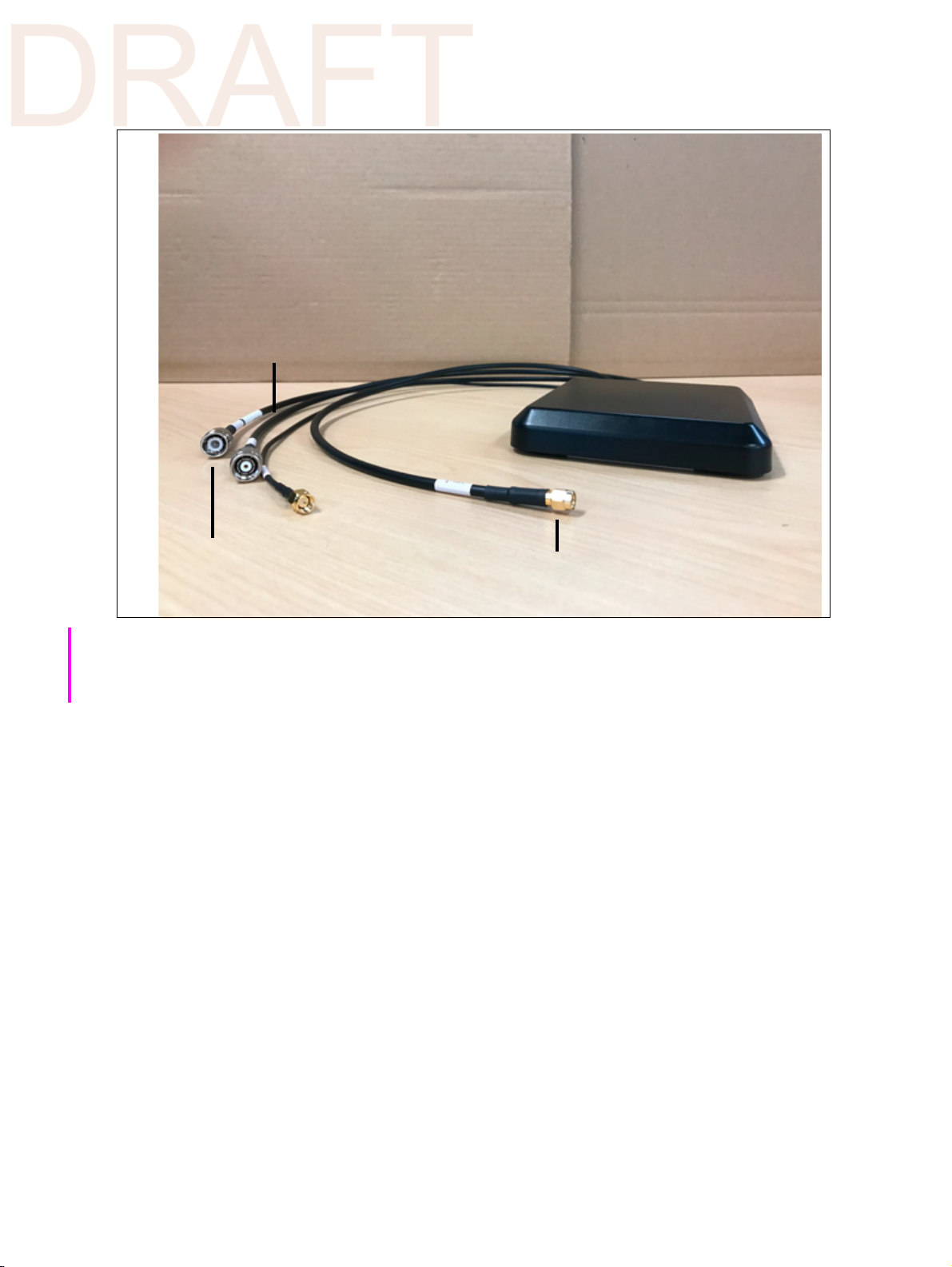
Antenna connectors
The SNM941 device has four connectors that connect to the 4-In-1 antenna, Trimble P/N 112057:
• GNSS antenna connector – This connector is a SMA jack.
• Two cellular modem connectors – One connector is a TNC jack and other is a reverse polarity SMA
(RP-
SMA) jack.
• Wireless Local Area Network (WLAN or Wi-Fi) antenna connector – This connector is a reverse
polarity
The Trimble-certified supplied GNSS, WLAN/Wi-Fi and ce
housing. Figure 2.1 on page 10 shows the locations of these connectors.
For more information, see Chapter 4, Installation.
C
TNC jack.
llular antennas are combined in a single
CAUTION – The antenna body does not provide a grounding path.
SNM941 Connected Site Gateway Installation Guide | 11
Page 12
2 | Overview
4-In-1 antenna
Wi-Fi antenna
connector - RP-TNC jack
Cellular antenna
connector - TNC jack
Cellular antenna
connector - RP-SMA jack
GNSS antenna
connector - SMA jack
DRAFT
Figure 2.2 4-In-1 antenna (P/N 112057)
Mounting provisions
The SNM941 and antenna is intended to be mounted directly to the asset that is being monitored, with
the exception of the machine chassis. The bottom of the antenna has an industrial adhesive that can be
used to mount the antenna directly to the device/machine. The antenna can only be directly adhesive
mounted to non-metallic surfaces that do not have metal immediately underneath. If mounting to a
metallic surface, you need an antenna riser, P/N 112056. The riser can be mounted with fasteners,
adhesive, or magnets.
In cases where the adhesive will not adequately s
antenna to the riser P/N 112056 ahead the time in a warm environment. Then fix to the asset using
fasteners or magnets.
In the case of installations where extreme vibration may be encountered, such as directly on the chassis
o
a tracked machine, you should mount the SNM941 using a mechanical shock isolation system.
f
NOTE – The top of the antenna should face the open sky. No other antenna should be installed within
20 cm (
For more information, see Chapter 4, Installation.
7.8") of this antenna.
ick, especially in cold environments, mount the
t
Electrical harness
The electrical harness depends on the machine installation.
For details, see Chapter 6, SNM941 Wiring Harness.
SNM941 Connected Site Gateway Installation Guide | 12
Page 13

3
DRAFT
3
Recommended Tools and
Supplies
► Tools
► Supplies
Every SNM941 installation will vary due to unique features of the asset being equipped.
The tools and supplies listed below are the absolute minimum required to complete an SNM941
installation. A complete mechanic’s field tool kit is preferred.
NOTE – Holes will most likely need to be drilled into the machine for installation purposes. Ensure that
the area drilled will not void contract or warranty on machine while not compromising the safety of the
operator.
SNM941 Connected Site Gateway Installation Guide | 13
Page 14

3 | Recommended Tools and Supplies
DRAFT
Tools
• Mechanic’s socket set
• Mechanic’s open-end wrench set
• Assorted screw drivers
• Digital multimeter
• Drill
• Assorted metal drill bits
Supplies
• (4) ¼" or 6 mm fasteners – either nuts and bolts with suitable washers (stainless steel is preferred)
or self-tapping screws
•Tie wraps
• Electrical tape
• Cable sheathing such as split loom
Optional additional supplies may include SNM941 mounting brackets, antenna mounting brackets, and
shock mounts.
SNM941 Connected Site Gateway Installation Guide | 14
Page 15

4
DRAFT
4
Installation
► General installation approach
► AccuGrade/GCS900 gateway device installation
► Trimble Earthworks gateway device installation
► Complete the device connections
This chapter describes the general procedure to install an SNM941 device and its necessary peripheral
devices. Trimble assumes you have a basic knowledge of mechanical and electrical technical operations.
For a list of recommended tools and supplies for installation, see Chapter 3, Recommended Tools and
Supplies.
NOTE – Before installing any telematics device, note its serial number for later reference.
SNM941 Connected Site Gateway Installation Guide | 15
Page 16

4 | Installation
DRAFT
General installation approach
In general, the installation is a simple process, however, failure to follow correct installation guidelines
will result in a non-functional or dysfunctional unit. Before starting the installation process, consider the
following guidelines:
• Installation length of components and length of connection wires to main unit. Keep in mind that it is
easier to extend the length of wires from asset terminals rather than change the location of the
antennas or control box.
• Ensure that you are prepared with various installation tools as each installation can be unique to the
machine that it is installed on.
The installation can be performed by doing the following tasks:
1. Determine the mounting location for the SNM941 device.
2. Determine the mounting location for the 4-In-1 antenna. The length of the cabling on the antenna to
the SNM941 is 0.6 m. Antenna extension cable is available.
3. Plan the route of the electrical harness.
4. Secure the SNM941 device.
5. Install the fuses – telematics installation only.
6. Make the electrical connections – telematics installation only.
7. Complete the device connections.
Further installation notes
• The SNM941 is designed for use on construction equipment. Attaching to the vehicle chassis or
body is standard procedure and will work well. If possible, avoid attaching the device to a
subcomponent that is prone to extreme shock or vibration, such as the engine block, or suspension
components. On a tracked machine, isolation mounts (P/N 84264-20 for telematics and
Accugrade/GCS installations, and P/N 109530 for Earthworks installations) may be required if
mounting directly to the chassis.
• Ensure that the chosen mounting location of the SNM941 is in a practical location. If installing for a
specific customer, confirm with the customer that the chosen location is acceptable. For example,
installation in the lunch box compartment may not be an acceptable location.
• Electrical Interference – The SNM941 device operates well in electrically noisy environments, but
installation best practices include avoiding close proximity to alternators, generators, electric
motors, DC to AC converters, switching power supplies, and arc welding equipment. If electrical
interference is suspected, enclose the SNM941 device wiring harness in a grounded shield wrap or
grounded conduit.
SNM941 Connected Site Gateway Installation Guide | 16
Page 17

4 | Installation
DRAFT
Guidelines for antenna mounting – adhesive mount
1. The cure time to reach full strength at room temperature is 24 hours. The longer it can be mounted
before being placed into service, the better.
2. Cure time is longer for environments 10
3. Adhesive mounting should not be attempted below 10
4. The cure time can be greatly accelerated by preheating the mounting surface and adhesive with a
heat gun, as shown in the graph below:
5. The mounting surface should be flat within 2 mm.
6. If placing on a glossy surface, it is best to lightly abrade the surface before final cleaning.
7. Adequate clean the surface: remove all dust, grease and grim and then use an alcohol wipe. A
cleaning towel and alcohol wipe are provided with P/N 112056. Allow all the cleaning agent to
vaporize before attempting to place the adhesive tape on the cleaned surface.
° C (50° F) to room temperature.
° C without supplemental heat.
8. When mounting the riser to a steel surface, you can use magnets to help fixture the antenna while
the adhesive cures.
Guidelines for antenna mounting – riser mount
Antenna Riser mount, P/N 112056
A variety of options are available for attaching the antenna–riser combination to the asset. The options
provided are outlined below.
1. Mont the antenna to the pedestal.
2. There are multiple mounting features once the antenna is mounted to the unit:
a. Fastener mounting option 1:
– 4x M4 fasteners into thread inserts from below
SNM941 Connected Site Gateway Installation Guide | 17
Page 18

b. Fastener mounting option 2:
DRAFT
– Fasteners from above into mounting plate tabs
– Sized for M6 Fasteners
– Quantity of 3 used at a minimum
c. Fastener mounting option 3:
4 | Installation
– Fasteners from above into mounting plate tabs
– Sized for M6 Fasteners
– Quantity of 3 used at a minimum
d. Magnetic mount:
– High Strength Rare Earth Magnets in 4 locations
– Covered with a rubber boot that resists sliding and damage to the mounting surface
TIP – Remove the mounting tab plate from the riser so that the magnets are exposed by
removing the four M4 flat head fasteners.
e. Adhesive mount:
– Use 3 mm foam adhesive tape for slightly out flat surfaces.
– Use magnets to help fixture during adhesive curing.
SNM941 Connected Site Gateway Installation Guide | 18
Page 19

4 | Installation
DRAFT
AccuGrade/GCS900 gateway device installation
Determine the mounting location of the SNM941 device
The SNM941 can be installed in various locations; however the recommended location is in the cab or a
side compartment, but not the engine compartment, to allow for:
• ease of access
•increased security
• a minimal distance from the antennas and control box to the main unit.
• SIM card access
The SNM941 mounting plate is designed to be fixed in an area with the dimensions of 185 mm x 230 mm
(7.28 in x 9.05 in), to allow adequate space for attachment of the electrical harness, as well as the
coaxial antenna connections.
CAUTION – Maximum operating temperature is +85° C and maximum storage temperature is
C
+85° C.
Be sure to avoid mounting the unit in an area with excessive exposure to moisture, dirt, direct heat,
sunlight and chemicals, while still allowing for accessibility, as well as good air flow.
Plan the route of the electrical harness
Keep in mind the following factors:
• The 34-pin connector on the electrical harness must reach and attach to the SNM941 device. It is not
necessary to plug the connector into the SNM941 at this time. Be sure to disconnect the harness
before beginning make any other electrical harness connections in steps 3 & 4.
• Ensure that the brown connector on the SNM941 harness can easily reach the corresponding brown
connector on the GCS/AccuGrade harness. If there is no brown connector on the GCS/AccuGrade
harness, refer to the SNM941 Ordering Guide (this can be found online in the Trimble Store help
files).
Secure the SNM941 device
• Trimble recommends that you use the provided mounting bracket for installation of the SNM941. If
the chosen mounting location is outside of the cab on a tracked vehicle, then the shock plate must be
used. Please note that the shock mount must be bolted to the machine. In most cases this means
that the holes must be drilled to accommodate for this.
• If the mounting bracket is not to be used, drill a rectangular array of 7 mm (¼") holes with the
dimensions of 215.4 mm x 60 mm (8.48" x 2.36").
• Secure the SNM941 to the mounting position using four M6 or ¼" bolts, nuts, and washers.
• Firmly tighten the bolts.
SNM941 Connected Site Gateway Installation Guide | 19
Page 20

4 | Installation
DRAFT
Determine the location of the 4-In-1 antenna
The antenna locations will have a significant effect on the performance quality of the SNM941 device.
• Mount antenna with the face of the antenna horizontal with the open sky, in an area that has a clear
° view of the sky and is at least 20 cm from all other transmitting antennas, the operator and any
360
other occupant, while still allowing the antenna cables to easily reach the SNM941.
• The antenna should not be easily sighted, to reduce the chances of tampering or disablement.
• The antennas should be firmly attached to the asset so that they will not come loose due to shock,
vibration, or thermal cycling.
• The antenna may be mounted directly to a horizontal surface near the top of the asset using the
industrial adhesive or the antenna bracket.
• The antenna must mounted at least 1" from metal structures and surfaces. Use the Trimble antenna
mounting bracket to position the antenna away from metal as needed.
• If the SNM941 is mounted more than 600 mm from the antenna, you must use the extension cable
set P/N 110046-44. The extensions will be 4.4 m in length. Typically these will be required if the
SNM941 is chassis mounted. When routing the extension cables make sure to avoid sharp corners,
excessive heat sources, frequent flexing of the coax cables, an extremely tight bend radius, or
sources of electrical noise.
CAUTION – The antenna connectors and extension cable connectors must be isolated from
C
chassis ground.
SNM941 Connected Site Gateway Installation Guide | 20
Page 21

4 | Installation
DRAFT
Trimble Earthworks gateway device installation
Determine the mounting location of the SNM941 device
The SNM941 can be installed in various locations; however the recommended location is near the cab
roof-line, typically with the SNR radio. to allow for:
• ease of access
• a minimal distance from the antenna
• SIM card access
The SNM941 mounting is designed to be mounted concurrently with the SNR radio and to allow
adequate space for attachment of the electrical harness, as well as the coaxial antenna connections.
Plan the route of the electrical harness
Keep in mind the following factors:
• The 34-pin connector on the electrical harness must reach and attach to the SNM941 device. It is not
necessary to plug the connector into the SNM941 at this time. Be sure to disconnect the harness
before beginning to make any other electrical harness connections.
• Connect the Internet Gateway connector to the Internet ETH 2 connector on the Earthworks
harness.
Secure the SNM941 device
Mount the SNM941 with the SNR Radio, using one of the following methods:
• Stack the SNM941 mounting bracket between the SNR radio and the provided base bracket.
SNM941 Connected Site Gateway Installation Guide | 21
Page 22

4 | Installation
DRAFT
• Mount the SNM941 side-by-side with the SNR radio: mount off existing SNR bracket, or on isolated
cab structure, as shown:
Determine the location of the antenna
The antenna location will have a significant effect on the performance quality of the SNM941 device.
• Mount the antenna in an area that has a clear 360
transmitting antennas, the operator and any other occupant, while still allowing the antenna cables
to easily reach the SNM941.
• The antenna should not be easily sighted, to reduce the chances of tampering or disablement.
• The antenna should be firmly attached to the asset so that they will not come loose due to shock,
vibration, or thermal cycling.
• The antenna may be mounted directly to a horizontal surface near the top of the asset using the
industrial adhesive or the antenna bracket, Trimble P/N 112056.
• The antenna must mounted at least 1" from metal structures and surfaces. Use the Trimble antenna
mounting bracket to position the antenna away from metal as needed.
° view of the sky and is at least 20 cm from all other
Complete the device connections
• Attach the antenna connectors to the SNM941.
• For use with GCS900 or AccuGrade systems, plug the brown connector from the SNM941 harness to
the corresponding brown connector on the GCS900 or AccuGrade harness.
• For use with Earthworks, plug the Internet Gateway connector from the SNM941 harness to the
corresponding Internet Eth 2 on the machine control harness. Attach the input harness to the
SNM941.
• Turn the machine on and observe to see the flashing LEDs.
SNM941 Connected Site Gateway Installation Guide | 22
Page 23

5
DRAFT
5
Locating the R Terminal
The location of the R terminal differs depending on the alternator used in the machine. If you cannot
locate the alternator’s R terminal, contact a qualified service technician for that machine.
The following are some examples of different alternators used in heavy machines, and the location of
the R terminal.
On machines that do not have an R terminal signal connection or a similar connection that is only active
when the engine is running, connect the R terminal wire directly to the yellow key switch wire. Both of
these inputs can be driven by a key-switched signal source. In this case, engine hours are accrued when
the key switch is on, even if the engine is not running.
SNM941 Connected Site Gateway Installation Guide | 23
Page 24

5 | Locating the R Terminal
DRAFT
In situations in which an alternator pictured above is not applicable, R terminal can be determined by
using a voltage meter. Clip the Alternator Wires (be careful to do this far enough from the alternator to
repair the wire and make the final connection).
The alternators typically have 3 outputs. To determine the R-terminal look for a wire that shows all of the
following behavior:
• No voltage when the machine is off.
• No voltage when the machine Key switch is on, but the engine is not running.
• DC voltage equivalent to battery or pulse signal of 50 Hz or greater when the machine engine is
running.
frequency adjusted to account for pulse signals.
This connection should be made in parallel to the output. After connecting the white R terminal wire to
the identified R terminal, run the machine for a minimum of 10 minutes to confirm in the web service
tool that the correct run time is accruing.
In some cases the alternator may be sending a pulse signal, or be outside the correct supported
frequency to register. If service hours are not reporting correctly, it is possible to connect to the positive
output of the oil pressure gauge, but this should only be done if the R terminal is not a workable solution.
For pulse signals it may show half of battery voltage, so confirm that you have your
SNM941 Connected Site Gateway Installation Guide | 24
Page 25

6
DRAFT
SNM941 Wiring Harness
► SNM941 wiring harness
► Telematics installation wires configuration
► Brown connector pinouts
► Earthworks, 8-pin connector pinouts
► Recommended DC electrical specifications
6
This chapter describes the SNM941 wiring harnes
s and electrical connections in detail.
SNM941 Connected Site Gateway Installation Guide | 25
Page 26

6 | SNM941 Wiring Harness
DRAFT
SNM941 wiring harness
The SNM941 wiring harnesses are 186940-02 for AGCS systems and 201641-46 for Earthworks. They
derive the best available power from the Brown connector. For telematics the harness may need to be
modified to change the power input wires from the Brown connector and re-routed to the appropriate
power source.
SNM941 Connected Site Gateway Installation Guide | 26
Page 27

6 | SNM941 Wiring Harness
P1 - 34-pin connector
P5 - Brown connector
P4 - Three
socket
connector
Connect to bulkhead on
the SNM941
Connect to CANbus
Connect to corresponding
brown connector on
GCS900 or AccuGrade harness
DRAFT
The following table describes the conductors in the Wiring harness kit.
34-Pin
Connector
1 Battery - Input Black J4 -Brown Connector - Pin 2 Black J2 -8 Pin Connector - Pin 2
3 Chassis Sense Green J2 - Ring Terminal Green J3 - Ring Terminal
5 Key Switch Input Yellow J4 -Brown Connector - Pin 1 Brown J2 - 8 Pin Connector - Pin 7
6 Analog Input Purple J5 - 6 Socket Connector - Pin 5 Purple J5 - 6 Socket Connector -
7 Digita
9 Eth
10 Ethernet TX+ White J4 -Brown Connector - Pin 5 White J2 -8 Pin Connector - Pin 6
12 RS-232 TX Pink J4 -Brown Connector - Pin 10 N/A
13 CAN A Low Green J6 - 3 Socket Connector - Pin B Green J6 - 4 Socket Connector -
14 CA
19 Batt
22 Digital Input 3 Orange J5 - 6 Socket Connector - Pin 4 Orange J5 - 6 Socket Connector -
23 R-
24 Digita
Signal
Description
Wire
Color
l Input 1 Brown J5 - 6 Socket Connector - Pin 2 Brown J5 - 6 Socket Connector -
ernet TX- Green J4 -Brown Connector - Pin 6 Orange J2 -8 Pin Connector - Pin 5
N A High Yellow J6 - 3 Socket Connector - Pin A Yellow J6 - 4 Socket Connector -
ery + Input Red J4 -Brown Connector - Pin
Terminal Input White J5 - 6 Socket Connector - Pin 1 White J5 - 6 Socket Connector -
l Input 2 Blue J5 - 6 Socket Connector - Pin 3 Blue J5 - 6 Socket Connector -
186940-02 201641-46
Te r m i n a t i o n Wire
Color
Blue J
1/12
Te r m i n a t i o n
Pin
5
Pin 2
Pin
3
Pin 2
2 - 8 Pin Connector - Pin 1
Pin 4
Pin 1
Pin 3
SNM941 Connected Site Gateway Installation Guide | 27
Page 28

6 | SNM941 Wiring Harness
DRAFT
34-Pin
Connector
26 Ethernet RX- Blue J4 -Brown Connector - Pin 8 Blue J2 - 8 Pin Connector - Pin 4
27 Ethernet RX+ Brown J4 -Brown Connector - Pin 7 Brown J2 - 8 Pin Connector - Pin 3
29 RS-232 RX Orange J4 -Brown Connector - Pin 3 N/A
32 RS-232 Ground Green J4 -Brown Connector - Pin 11 N/A
Pin numbers not listed above are not connected in the wiring harness. For additional detail on the nature
of the signal connections, see table on page 29.
NOTE – All electrical c
be 18 AWG or larger.
Signal
Description
186940-02 201641-46
Wire
Color
onductors used in the installation of an SNM941 Connected Site Gateway must
Te r m i n a t i o n Wire
Color
Te r m i n a t i o n
SNM941 Connected Site Gateway Installation Guide | 28
Page 29

Telematics installation wires configuration
DRAFT
The following table describes the conductors in the electrical harness:
6 | SNM941 Wiring Harness
Conductor IDConductor
Pin
Number*
A5 Key Switch
B19Battery +
C1 Battery -
E 3 Chassis
Signal
description
Input
Input
Input
Ground
Connection
An electrical accessory circuit that becomes active
when the asset’s key switch is moved to the “accessory”
and “run” positions.
Required to initialize the SNM941 as soon as an operator
activates an asset.
NOTE – If this connection is not made, the device will
shut off after 10 minutes of run time.
Positive terminal on battery. Terminal with the highest
voltage in multi-battery configurations.
Required to provide continuous power to the SNM941.
Negative terminal on battery. Terminal that connects to
chassis ground in multi-battery configurations.
Required to provide continuous power to the SNM941.
Reliable connection to asset’s conductive chassis.
Required to detect open negative master disconnect.
Required EMI connection to asset’s conductive chassis.
Failure to make this connection could cause erratic
behavior on the device.
The following table describes the conductors in the 6-pin Deutsch connector on the electrical harness:
Conductor IDConductor
Pin
Number*
D23R-Terminal
F 7 Digital Input 1 Brown Optional – A sensor that provides a ground
Signal
description
Input
Wire
color
White The relay terminal on the engine’s
Connection
alternator or a signal such as an oil
pressure switch that provides a signal of
85% of system voltage or greater.
This signal is used to determine runtime
hours. If the R-terminal is not accessible,
see Chapter 5, Locating the R Terminal.
signal when a monitored situation occurs. If
not used connect to ground or let float. This
can be an open circuit or short circuit to
ground, i.e. when the monitored state
occurs, the signal should be ground.
For more information, see Brown connector
pinouts, page 30 or refer to the GCSFlex
Installation Guide.
SNM941 Connected Site Gateway Installation Guide | 29
Page 30

6 | SNM941 Wiring Harness
- E - Symbol designates reduced wire seal
DRAFT
Conductor IDConductor
Pin
Number*
G 24 Digital Input 2 Blue Optional – A sensor that provides a ground
H 22 Digital Input 3 Orange Optional – A sensor that provides a system
I 6 Analog Input Purple Optional – A sensor with an analog output
For more information on conductor pin numbers, see the Wiring Harness kit table on page 27.
Signal
description
Wire
color
Connection
signal when a monitored situation occurs. If
not used connect to ground or let float. This
can be an open circuit or short circuit to
ground, i.e. when the monitored state
occurs the signal should be ground.
voltage signal when a monitored situation
occurs. Connect to system voltage or let
float. This will cause the unit to wake up
when the asset is in low power mode.
or an accessory electrical circuit where
voltage monitoring is required. This sensor
must be no greater than system voltage.
Brown connector pinouts
The following figure shows the configuration of the brown connector.
The following table describes the configuration of the pinouts.
Pin Function GCS900 SNM941
1 Switched Power. Power available only when the 3D system is on. Yes Yes
2Power Ground Yes Yes
3 RS-232 TX Display, RX Radio (AGCS RS-232-0) Yes Yes
4 CAN Hi (GCS CAN-0) Yes No
5 Ethernet TXD+ Yes Yes
186940-02
SNM941 Connected Site Gateway Installation Guide | 30
Page 31

6 | SNM941 Wiring Harness
DRAFT
Pin Function GCS900 SNM941
186940-02
6 Ethernet TXD- Yes Yes
7 Ethernet RXD+ Yes Yes
8 Ethernet RXD- Yes Yes
9 CAN Low (GCSCAN0) Yes No
10 RS-232 TX Display, RX Radio (AGCS RS-232-0) Yes Yes
11 RS-232 Ground No No
12 Typically unswitched power. Power is always available (may not
be applicable to all base kits).
For more information on the nature of the signal connections, see Recommended DC electrical
specifications, page 32.
Some Yes
SNM941 Connected Site Gateway Installation Guide | 31
Page 32

Earthworks, 8-pin connector pinouts
DRAFT
The following table describes the configuration of the pinouts.
Pin Function
1Battery +
2Power Ground
3 Ethernet RX+
4 Ethernet RX-
5 Ethernet TX-
6 Ethernet TX+
7Keyswitch Power
8N/A
Recommended DC electrical specifications
6 | SNM941 Wiring Harness
Item Symbol Min. Ty p . Max. Unit
Supply Voltage V
Supply Current, Active Mode
Supply Current, Hibernate Mode
Supply Current, Daily Average
Pulse Input Voltage High
Pulse Input Voltage Low V
Ignition High Voltage V
Ignition Low Voltage (including open circuit) V
Ignition Input Pull-down Resistance R
Digital Switch To Ground Input Voltage High V
Digital Switch To Ground Input Voltage V
Digital Switch To Battery Input Voltage High
Digital Switch To Battery Input Voltage Low
Analog Input Voltage V
1
Max tested at Vin = 7 V, cell on and idle, Wi-Fi on and Carrier being transmitted, relay driver sourcing 200 mA, Filtered Power
Out sourcing 200mA, USB sourcing 500mA.
2
Typical measurements taken with external voltage of 12.0 V.
3
Measurement calculated based on average current consumption over a 24 hour period multiplied by 24 hours.
4
Typical at 14V, 2 EIA/TIA-232-F Compliant, 3 EIA/TIA-485-B Compliant.
5
This measurement applies only if the PulseIn-2 input is configured as a digital input.
6
This input can also be left floating to represent an input low signal.
1,2
2
2,3
4
5
5,6
BATT
I
BATT
I
BATT
I
BATT
V
RTH
RTL
IGIH
IGIL
IGN
DIH
DIL
V
SBIH
V
SBIL
ANALOG
7 24 32 Vo l t s
190 233 1500 mA
— 5 12 mA
— 600 — mA-h
85 %V
55 %V
80 — — %V
— V
7 10 kΩ
2.5 V
1.0 V
85 %V
0 100 %V
IGIH
-1
V
55 %V
BATT
BATT
BATT
BATT
BATT
BATT
SNM941 Connected Site Gateway Installation Guide | 32
Page 33

7
DRAFT
7
Installing the SIM Card
Many versions of the SNM941 device come with a Trimble-supplied SIM card. In some circumstances,
such as needing a high data rate plan for a grade control system, you may need to replace this standard
SIM card with another. This chapter details how to successfully replace the SIM card. Before changing
the SIM card, contact your local Trimble SNM941 dealer to determine if a different SIM is necessary.
Replacing the SIM card
The SIM card door is located at the back of the enclosure, away from the 34-pin connector. Ensure that
the SIM pin number is entered into web interface, TB5x0, or CB4x0 before you replace the SIM.
1. When you replace the SIM card, ensure you are working in a dry and clean environment.
2. Remove the power from the SNM941 device during this procedure.
3. To reduce the chances of electrostatic discharge (ESD) damage, discharge the SNM941 enclosure to
chas
4. Remove the two screws from the SIM door and open the SIM door.
5. Gently push the SIM card towards the front of the devic
the SIM card towards you.
ground before starting work.
sis
e. This will trigger a release which will eject
SNM941 Connected Site Gateway Installation Guide | 33
Page 34

7 | Installing the SIM Card
DRAFT
6. Carefully remove the SIM card taking care not to touch the gold connectors.
7. To install new SIM card:
a. Hold the SIM card with the notch side going in first and the gold contacts facing down towards the
PCB.
. Insert into the slot and then gently push in, t
b
NOTE – The SIM card will not insert completely into unit. This is normal.
NO
TE – It is rec
ommended to use only industrial grade SIM card with 2FF form factor.
o trigger the locking mechanism.
SNM941 Connected Site Gateway Installation Guide | 34
Page 35

DRAFT
Limited Warranty Terms and
Conditions
Product Limited Warranty
Subject to the following terms and conditions, Trimble Inc. (“Trimble”)
warrants that for a period of one (1) year from date of purchase this
Trimble product (the “Product”) will substantially conform to Trimble's
publicly available specifications for the Product and that the hardware
and any storage media components of the Product will be substantially
free from defects in materials and workmanship.
Product Software
Product software, whether built into hardware circuitry as firmware,
provided as a standalone computer software product, embedded in
flash memory, or stored on magnetic or other media, is licensed solely
for use with or as an integral part of the Product and is not sold. If
accompanied by a separate end user license agreement (“EULA”), use
of any such software will be subject to the terms of such end user
license agreement (including any differing limited warranty terms,
exclusions, and limitations), which shall control over the terms and
conditions set forth in this limited warranty.
Software Fixes
During the limited warranty period you will be entitled to receive such
Fixes to the Product software that Trimble releases and makes
commercially available and for which it does not charge separately,
subject to the procedures for delivery to purchasers of Trimble
products generally. If you have purchased the Product from an
authorized Trimble dealer rather than from Trimble directly, Trimble
may, at its option, forward the software Fix to the Trimble dealer for final
distribution to you. Minor Updates, Major Upgrades, new products, or
substantially new software releases, as identified by Trimble, are
expressly excluded from this update process and limited warranty.
Receipt of software Fixes or other enhancements shall not serve to
extend the limited warranty period.
For purposes of this warranty the following definitions shall apply: (1)
“Fix(es)” means an error correction or other update created to fix a
previous software version that does not substantially conform to its
Trimble specifications; (2) “Minor Update” occurs when enhancements
are made to current features in a software program; and (3) “Major
Upgrade” occurs when significant new features are added to software,
or when a new product containing new features replaces the further
development of a current product line. Trimble reserves the right to
determine, in its sole discretion, what constitutes a Fix, Minor Update,
or Major Upgrade.
Warranty Remedies
If the Trimble Product fails during the warranty period for reasons
covered by this limited warranty and you notify Trimble of such failure
during the warranty period, Trimble will repair OR replace the
nonconforming Product with new, equivalent to new, or reconditioned
parts or Product, OR refund the Product purchase price paid by you, at
Trimble’s option, upon your return of the Product in accordance with
Trimble's product return procedures then in effect.
How to Obtain Warranty Service
To obtain warranty service for the Product, please contact your local
Trimble authorized dealer. Alternatively, you may contact Trimble to
request warranty service at +1-408-481-6940 (24 hours a day) or email your requ est to trimble_support@trimble.com. Please be prepared
to provide:
– your name, address, and telephone numbers
– proof of purchase
– a copy of this Trimble warranty
– a description of the nonconforming Product including the model
number
– an explanation of the problem
The customer service representative may need additional information
from you depending on the nature of the problem.
Warranty Exclusions and Disclaimer
This Product limited warranty shall only apply in the event and to the
extent that (a) the Product is properly and correctly installed,
configured, interfaced, maintained, stored, and operated in accordance
with Trimble's applicable operator's manual and specifications, and; (b)
the Product is not modified or misused. This Product limited warranty
shall not apply to, and Trimble shall not be responsible for, defects or
performance problems resulting from (i) the combination or utilization
of the Product with hardware or software products, information, data,
systems, interfaces, or devices not made, supplied, or specified by
Trimble; (ii) the operation of the Product under any specification other
than, or in addition to, Trimble's standard specifications for its
products; (iii) the unauthorized installation, modification, or use of the
Product; (iv) damage caused by: accident, lightning or other electrical
discharge, fresh or salt water immersion or spray (outside of Product
specifications); or exposure to environmental conditions for which the
Product is not intended; (v) normal wear and tear on consumable parts
(e.g., batteries); or (vi) cosmetic damage. Trimble does not warrant or
guarantee the results obtained through the use of the Product, or that
software components will operate error free.
NOTICE REGARDING PRODUCTS EQUIPPED WITH TECHNOLOGY
PABLE OF TRACKING SATELLITE SIGNALS FROM SATELLITE
A
C
BASED AUGMENTATION SYSTEMS (SBAS) (WAAS/EGNOS, AND
MSAS), OMNISTAR, GNSS, MODERNIZED GNSS OR GLONASS
SATELLITES, OR FROM IALA BEACON SOURCES:
NOT RESPONSIBLE FOR THE OPERATION OR FAILURE OF
OPERATION OF ANY SATELLITE BASED POSITIONING SYSTEM
OR THE AVAILABILITY OF ANY SATELLITE BASED POSITIONING
SIGNALS.
THE FOREGO ING LIMITED WARRANTY TERMS STATE TRIMBLE’S ENTIRE
LIABILITY, AND YOU R EXCLUSIVE REMEDIES, RELATING TO THE TRIMBLE
PRODUCT. EXCEPT AS OTH ERWIS E EXPRESSLY PROVIDED HEREIN, THE
PRODUCT, AND ACCOMPANYING DOCUMENTATION AND MATERIALS ARE
PROVIDED “AS-IS” AND WITHOUT EXPRESS OR IMPLIED WARRA NTY OF
ANY KIND, BY EITHER TRIMBLE OR ANYONE WHO HAS BEEN INVOLVED IN
ITS CREATION, PRODUCTION, INSTALLATION, OR DISTRIBUTION,
INCLUDING, BUT NOT LIMITED TO, THE IMPLIED WARRA NTIE S OF
MERCHANTABILITY AND FITNESS FOR A PART IC UL AR PURP OSE, TITLE,
AND NONINFRINGEMENT. THE STATED EXPRESS WARRANTIES ARE IN LIEU
OF ALL OBLIGATIONS OR LIABILITIES ON THE PART OF TRIMBLE ARISING
OUT OF, OR IN CONNECTION WITH, ANY PRODUCT. BECAUSE SOME
STATES AND JURISDICTIONS DO NOT ALLOW LIMITATIONS ON DURATION
OR THE EXCLUSION OF AN IMPLIED WARRANTY, THE ABOVE LIMITATION
MAY NOT APPLY OR FULLY APPLY TO YOU.
TRIMBLE IS
Limitation of Liability
TRIMBLE'S ENTIRE LIABILITY UNDER ANY PROVISION HEREIN SHALL BE
LIMITED TO THE AMOUNT PAI D BY YOU FOR THE PRODUCT. TO THE
MAXIMUM EXTENT PERMITTED BY APPLICABLE LAW, IN NO EVENT SHALL
TRIMBLE OR ITS SUPPLIERS BE LIABLE FOR ANY INDIRECT, SPECIAL,
INCIDENTAL, OR CONSEQUENTIAL DAMAGE WHATSOEVER UNDER ANY
CIRCUMSTANCE OR LEGAL THEORY RELATING IN ANYWAY TO THE
PRODUCTS, SOFTWARE AND ACCOM PANYIN G DOCUMENTATION AND
MATERIALS, (INCLUDING, WITHOUT LIMITATION, DAMAGE S FOR LOSS OF
BUSINESS PROFITS, BUSINESS INTERRUPTION, LOSS OF DATA, OR ANY
OTHE R PECUNIARY LOSS), REGARDLESS OF WHETHER TRIMBLE HAS BEEN
ADVISED OF THE POSSIBILITY OF ANY SUCH LOSS AND REGARDLESS OF
THE COURSE OF DEALING WHICH DEVELOPS OR HAS DEVELOPED
BETWEEN YOU AND TRIMBLE. BECAUSE SOME STATES AND
JURISDICTIONS DO NOT ALLOW THE EXCLUSION OR LIMITATION OF
LIABILITY FOR CONSEQUENTIAL OR INCIDENTAL DAMAGES, THE ABOVE
LIMITATION MAY NOT APPLY OR FULLY APPLY TO YOU.
PLEASE NOTE: THE ABOVE TRIMBLE LIMITED WARRANTY
PR
OVISIONS WILL NOT APPLY TO PRODUCTS PURCHASED IN
THOSE JURISDICTIONS (E.G., MEMBER STATES OF THE
EUROPEAN ECONOMIC AREA) IN WHICH PRODUCT
WARRANTIES ARE THE RESPONSIBILITY OF THE LOCAL
TRIMBLE AUTHORIZED DEALER FROM WHOM THE PRODUCTS
ARE ACQUIRED. IN SUCH A CASE, PLEAS E CONTACT YOUR
LOCAL TRIMBLE AUTHORIZED DEALER FOR APPLICABLE
WARRANTY INFORMATION.
SNM941 Connected Site Gateway Installation Guide | 35
Page 36

Official Language
DRAFT
THE OFFICIAL LANGUAGE OF THESE TERMS AND CONDITIONS IS ENGLISH.
IN THE EVENT OF A CONFLICT BETWEEN ENGLISH AND OTHER LANGUAGE
VERSIONS, THE ENGLISH LANGUAGE SHALL CONTROL.
Registra tion
To receive information regarding updates and new products, please
contact your local Trimble authorized dealer or visit the Trimble website
at www.t rimbl e.com/regi ster. Upon registration you may select the
newsletter, upgrade, or new product information you desire.
Software Components
Refer to opensource.snm941.com.
SNM941 Connected Site Gateway Installation Guide | 36
Page 37

TRANSFORMING THE WAY THE WORLD WORKS
DRAFT
 Loading...