

Page 1

QUICK START GUIDE
www.xyz3d.net
北京昊云科技有限公司
TRIMBLE UX5 LAUNCHER
Before you use the Trimble® UX5 launcher, make sure that you have read and
understood all safety requirements in this guide.
This guide explains how to:
• Prepare the launcher.
• Use the launcher to launch the Trimble UX5 aerial imaging rover.
• Disassemble the launcher.
Before you head out to the
field, make sure the launcher
bag contains the following
items:
• Safety pin.
• Launch dock with lock
pin.
• V-support.
• Crank.
• Launch slide with
elastics.
1
Page 2
Preparing the launcher
www.xyz3d.net
北京昊云科技有限公司
You are prompted to prepare the launcher during the pre-flight checklist.
Step 1: Assemble the launcher
1. Unfold the launch slide.
C CAUTION – Take care when unfolding the launch slide as there are sharp
edges that can cause finger cuts.
2. Secure each section of the launch
slide by lifting the appropriate
handle and hooking it into the next
section of the launch slide. Close
the handles.
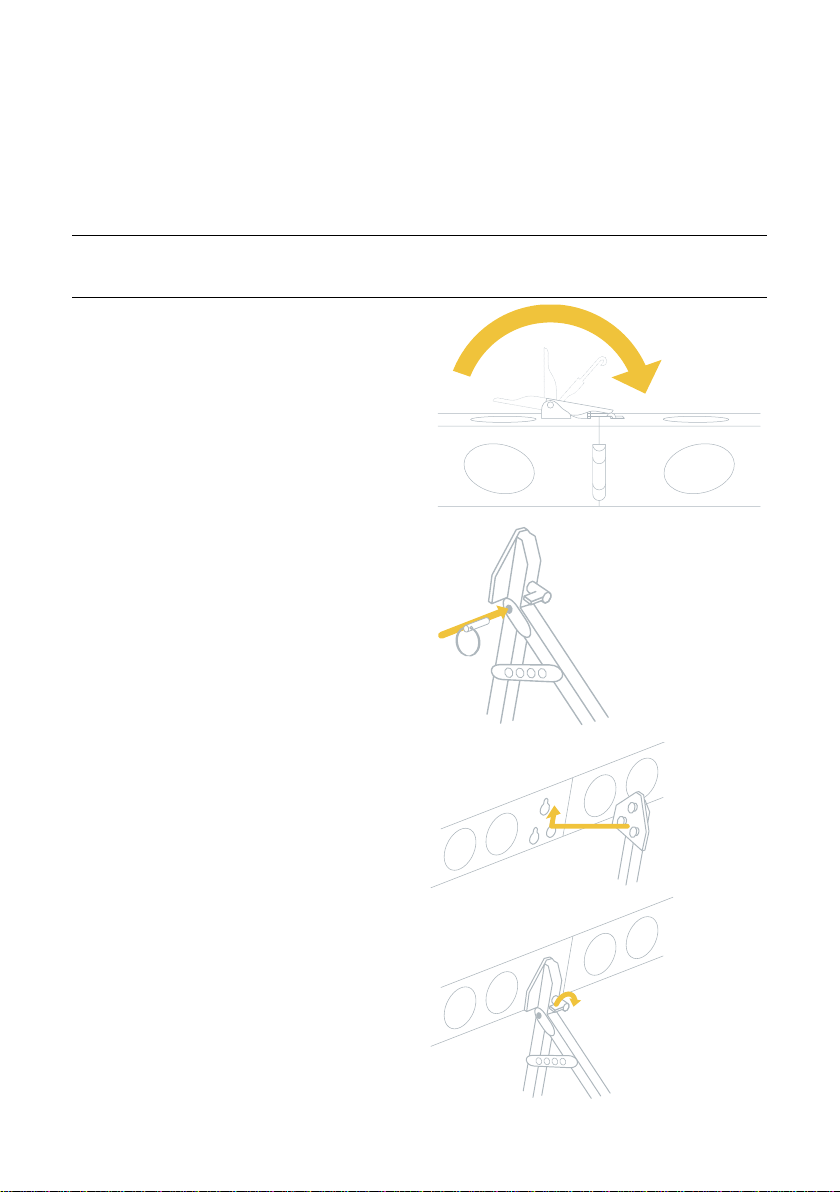
3. Unfold and secure the V-support
with the lock pin.
4. To attach the V-support to the
launch slide, make sure the knob is
pointing to the left and then insert
the V-support pins in the reserved
holes, situated approximately 2/3
of the length of the launch slide.
Turn the knob to the right to
tighten.
2
Page 3
Step 2: Attach launcher cord and launch dock
www.xyz3d.net
北京昊云科技有限公司
1. Pull the ends of the launcher cord out of the launch slide so that the cord lies
on top of the launcher slide.
Note – If the launcher cord is blocked while the elastics are not tightened, pull
the release handles upward to unblock them.
C CAUTION – Never push the release handles when there is tension on the
launcher cord. You will damage the elastics. If there is tension on the launcher
cord, see step 1 of “Disassembling the launcher.”
2. Position the launch dock on the end of the launch slide with the arrows
pointing in the direction of launch.
3. Slide the launch dock over the ends of the launcher cord.
4. To attach the ends of the launcher cord to the launch dock, remove the lock
pin from the launch dock and then slide the lock pin through the holes in the
launch dock, attaching the ends of the launcher cord as you do so. Secure the
lock pin.
3
Page 4

5. Slide the launch dock over the launch hook at the beginning of the launch
www.xyz3d.net
北京昊云科技有限公司
slide, making sure the launch dock clicks into position. Make sure the trigger
is not blocked.
6. Insert the safety pin into the launch dock.
C WARNING – Always keep the safety pin inserted in the launch dock. Remove
the safety pin only just before launch. Early removal of the launch pin can result
in accidental release of the launcher, causing serious personal injury and damage
to the UX5 or launcher.
C CAUTION – Never launch without the UX5 sitting on the dock as it will
damage the launch dock. The design of the launcher takes into account the
weight of the UX5 sitting on the launch dock.
4
Page 5

Step 3: Tighten the launcher cord elastics
www.xyz3d.net
北京昊云科技有限公司
1. Position the launcher at the planned takeoff location, with the launch
direction pointing into the wind.
2. Insert the crank onto the nut located toward the front end of the launch slide.
3. Stretch the launcher cord using the crank. In normal circumstances, the node
between the cord and elastic should be in the middle of the hole where
numbered “4” on the launcher.
C CAUTION – The launcher cord stretches with every launch. When you can
easily reach the last hole when tightening the cord, replace the launcher cord
to prevent unsuccessful launches and damage to the launcher or the UX5. For
more information, refer to the Trimble UX5 Aerial Imaging Solution Maintenance
Manual.
5
Page 6

Step 4: Place the UX5 onto the launcher
www.xyz3d.net
北京昊云科技有限公司
1. Position the UX5 at the front of the launch dock and use your finger tips to
guide the launcher slats on the underside of the UX5 onto the lips of the
launch dock.
C WARNING – Take care to ensure the UX5 is correctly positioned on the
launch dock. An incorrect position can result in launch failure, causing serious
personal injury and damage to the rover or launcher.
2. Use the artificial horizon indicator in the Aerial Imaging software to check
the pitch and roll of the UX5 on the launch dock. The pitch angle should be
between 20° and 30° and the roll angle should be between -5° and 5°. The
horizon should be positioned parallel to the UX5 on the artificial horizon
indicator. If you need to adjust the horizon, reposition the launcher.
6
Page 7

Launching the UX5
www.xyz3d.net
北京昊云科技有限公司
1. To remove the safety pin, position yourself behind the launcher, reach
carefully under the UX5 and then pull out the safety pin.
C WARNING – Always take care to avoid contact with the propeller blades. If
the UX5 receives a sudden shock while armed, the motor can unexpectedly start
causing the propeller blades to move. Contact with moving propeller blades can
result in serious personal injury.
2. Just before launch, perform the following safety checks:
• Make sure there are no aerial objects inside the zone of operation.
• Locate the UX5 on the Tablet screen.
• Make sure both crew members have a clear line of sight to the UX5.
• Make sure there are no obstacles or people near the front of the launcher.
C WARNING – Make sure you complete each of the safety checks listed at this
step. Failure to do so could result in serious personal injury and damage to the
UX5 or launcher.
3. When you have made sure that everything is clear in front of, above, and
behind the launcher, stand behind the launcher and press the launch handle
to launch the UX5.
C CAUTION – Never launch without the UX5 sitting on the dock as it will
damage the launch dock. The design of the launcher takes into account the
weight of the UX5 sitting on the launch dock.
4. If an obstacle such as a person or animal suddenly appears in the
obstacle clearance zone during takeoff, tap the FTS button in the
software. The UX5 immediately powers down and returns to the ground.
For more information, refer to the Trimble UX5 Aerial Imaging Solution User
Guide.
5. After launch, release the tension on the launcher cord. Leaving tension on the
launcher cord for extended periods can damage the elastics. See step 1 of
“Disassembling the launcher.”
7
Page 8

Disassembling the launcher
www.xyz3d.net
北京昊云科技有限公司
1. If you have not yet released the tension on the launcher cord, then do so now.
To release the tension, release the force with the crank very gently while
pulling the release handles in the front of the launcher upward. This is safest
done with two people, with one person carefully winding the crank counterclockwise to counteract the force on the elastics.
2. Remove the lock pin on the launch dock and detach the launcher cord.
3. Using the crank, tighten the launcher cord so that most of the cord is in the
launch slide but the end remains out.
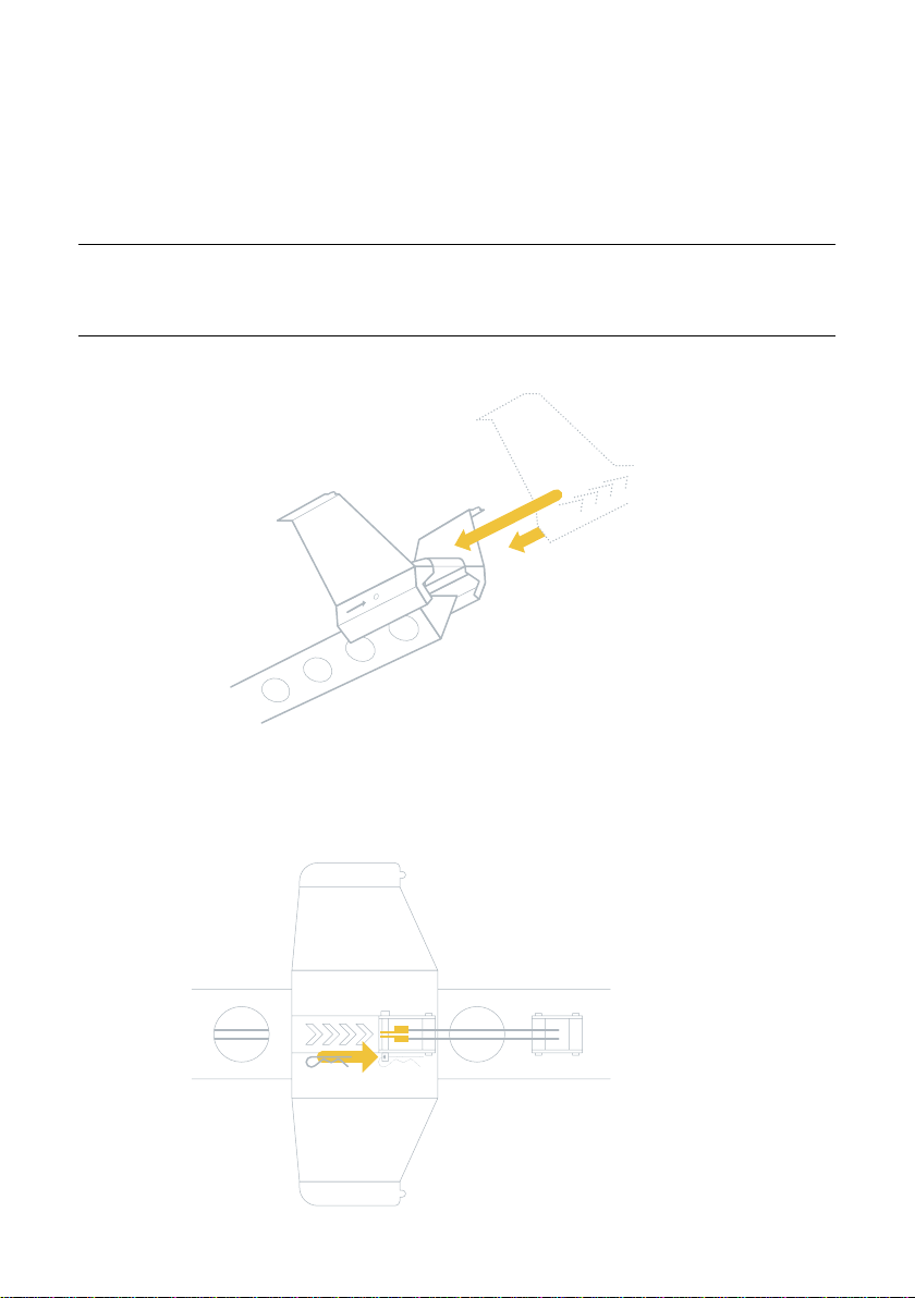
4. Slide the launch dock off the front of the launch slide.
5. To detach the V-support, turn the knob upward and then slide the pins out
of the holes in the launch slide. Remove the lock pin on the V-support to fold
the legs and then reinsert the lock pin.
C CAUTION – Take care when folding the V-support legs not to jam or cut
fingers.
6. Open the handle fixes on the launch slide and fold the launch slide.
7. Return all of the launcher items to the launcher bag.
© 2013, Trimble Navigation Limited. All rights reserved. Trimble and the Globe and Triangle logo are trademarks of Trimble
Navigation Limited, registered in the United states and in other countries. All other trademarks are the property of their
respective owners. Version 1.00, Revision B (July 2013).
www.trimble.com
UX-D00106-01
P/N UX-D00106 -01
8
Page 9

产品咨询:
北京昊云科技有限公司
地址:北京市海淀区信息路28号信息大厦7层
邮编:100086
电话:15010459204
邮箱:sales@xyz3d.net
网址:www.xyz3d.net
 Loading...