

Page 1

USER GUIDE
Trimble TX8 3D Laser Scanner
Version 1.00
Revision E
May 2016
1
Page 2
Corporate Office
Trimble Navigation Limited
935 Stewart Drive
Sunnyvale, CA 94085
USA
www.trimble.com
GeoSpatial business area
Trimble Navigation Limited
GeoSpatial business area
10355 Westmoor Drive,
Suite #100
Westminster, CO 80021
USA
800-538-7800 (toll free in USA)
+1-937-245-5600 Phone
+1-937-233-9004 Fax
http://www.trimble.com/support/
Legal Notices
© 2016, Trimble Navigation Limited. All rights reserved.
Trimble, the Globe & Triangle logo, and RealWorks are trademarks of
Trimble Navigation Limited, registered in the United States and in other
countries.
All other trademarks are the property of their respective owners.
Release Notice
This is the May 2016 release (Revision E) of the Trimble TX8 3D Laser
Scanner User Guide. It applies to version 1.00 of the 3D Laser Scanner.
Product Limited Warranty Information
For applicable product Limited Warranty information, please refer to the
Limited Warranty Card included with this Trimble product, or consult your
local Trimble authorized dealer.
Notices
USA
Class B Statement – Notice to Users. This equipment has been
tested and found to comply with the limits for a Class B digital device,
pursuant to Part 15 of the FCC rules and Part 90. These limits are
designed to provide reasonable protection against harmful interference
in a residential installation. This equipment generates, uses, and can
radiate radio frequency energy and, if not installed and used in
accordance with the instructions, may cause harmful interference to
radio communication. However, there is no guarantee that interference
will not occur in a particular installation. If this equipment does cause
harmful interference to radio or television reception, which can be
determined by turning the equipment off and on, the user is encouraged
to try to correct the interference by one or more of the following
measures:
– Increase the separation between the equipment and the receiver.
– Connect the equipment into an outlet on a circuit different from that to
which the receiver is connected.
– Consult the dealer or an experienced radio/TV technician for help.
Changes and modifications not expressly approved by the manufacturer
or registrant of this equipment can void your authority to operate this
equipment under Federal Communications Commission rules.
Canada
This Class B digital apparatus complies with Canadian ICES-003.
Cet appareil numérique de la classe B est conforme à la norme NMB-003
du Canada.
Europe
Australia and New Zealand
This product conforms with the regulatory requirements of the
Australian Communications and Media Authority (ACMA) EMC
framework, thus satisfying the requirements for RCM Marking and sale
within Australia and New Zealand.
Taiwan – Battery Recycling Requirements
The product contains a removable Lithium-ion battery. Taiwanese
regulations require that waste batteries are recycled.
廢電池 請 回 收
Waste Electrical and Electronic Equipment (WEEE)
For product recycling instructions and more information, please go to
www.trimble.com/Corporate/Environmental_Compliance.aspx.
Recycling in Europe: To recycle Trimble WEEE (Waste Electrical and
Electronic Equipment, products that run on electrical power.), Call +31
497 53 24 30, and ask for the “WEEE Associate”. Or, mail a request for
recycling instructions to:
Trimble Europe BV
c/o Menlo Worldwide Logistics
Meerheide 45
5521 DZ Eersel, NL
The Product has been tested and found to comply with the requirements
for a Class B device pursuant to European Council Directive 2014/30/EU
on EMC.
The Product complies with European Council Directive 2006/42/EC on
Machinery and European Council Directive 2011/65 (RoHS).
2 Trimble TX8 3D Laser Scanner User Guide
Page 3

FCC Declaration of Conformity
We, Trimble Navigation Limited.
935 Stewart Drive
PO Box 3642
Sunnyvale, CA 94088-3642
United States
+1-408-481-8000
Declare under sole responsibility that DoC products comply
with Part 15 of FCC Rules.
Operation is subject to the following two conditions:
(1) This device may not cause harmful interference, and
(2) This device must accept any interference received,
including interference that may cause undesired operation.
EC Declaration of Conformity
We, Trimble (MENSI S.A.S.)
174 avenue du Maréchal de Lattre de Tassigny
94120 Fontenay-sous-Bois
France
Declare under sole responsibility that the product, Trimble
TX8, part number 28000034 is in conformity with the
following European standards:
Electromagnetic Compatibility
:
Standard NF EN 61326-1 (July 2006)
In compliance with EMC Directive 2014/30/EU.
In compliance with Machinery Directive 2006/42/EC.
In compliance with RoHS Directive 2011/65 (RoHS).
Environment: Electrical equipment for measurement, control
and laboratory use
Conformity has been demonstrated on one production
representative sample. Conformity to EMC standards of each
manufactured unit is ensured by implementation of internal
documented procedures.
Declaration of Conformi ty (laser performance)
This is to certify that 3D scanner model
Trimble TX8
complies with the performance requirements of
IEC 60825-1
and
US FDA 21 CFR §1040.10
(1)
(2)
as a Class 1 laser device.
(1)
IEC 60825-1: 2007 Edition 2.0. Safety of laser products - Part
1: Equipment classification and requirements. IEC, Geneva.
(2)
Federal Performance Standard for Laser Products, 21 §CFR
1040.10, Center for Devices and Radiological Health, Silver
Springs, Maryland, USA.
Trimble TX8 3D Laser Scanner User Guide 3
Page 4
Safety Information
Before you use your Trimble product, make sure that you have read and understood all safety
requirements.
WARNING – This alert warns of a potential hazard which, if not avoided, could result in severe injury or even
death.
CAUTION – This alert warns of a potential hazard or unsafe practice that could result in minor injury or property
damage or irretrievable data loss.
Note – An absence of specific alerts does not mean that there are no safety risks involved.
Use and care
This product is designed to withstand the rough treatment and tough environment that typically
occurs in construction applications. However, the scanner is a high-precision electronic instrument
and should be treated with reasonable care.
Also see, Care and maintenance, page 19.
CAUTION – Operating or storing the instrument outside the specified temperature range can damage it.
Laser safety
This is to certify that the 3D scanner model, Trimble TX8, complies with the performance
requirements of IEC 60825-11 and US FDA 21 CFR §1040.102 as a Class 1 laser device.
Hazard label
This label is placed on each side of the instrument. It warns you to keep your hands away from
moving parts when the instrument is rotating. Failure to follow the instruction may cause injury to
yourself or damage to the instrument.
1
IEC 60825-1: 2007 Edition 2.0. Safety of laser products - Part 1: Equipment classification and requirements. IEC, Geneva.
2
Federal Performance Standard for Laser Products, 21 §CFR 1040.10, Center for Devices and Radiological Health, Silver Springs, Maryland, USA.
Trimble TX8 3D Laser Scanner User Guide 4
Page 5
Class 1 Laser Product label
The TX8 3D scanner complies with the performance requirements of international standard IEC
60825-1 2007 as a CLASS 1 LASER PRODUCT and is therefore labeled as follows in accordance with the
requirements of this standard. The Laser Warning Label is placed on the bottom and back of the
instrument.
The TX8 3D scanner operates in a laser wavelength of 1,5 µm (invisible light), with a beam divergence
of 0.177 mrad Gaussian and an output laser power of 6 kW peak.
Battery safety
WARNING – Do not damage the rechargeable Lithium-ion battery. A damaged battery can cause an explosion or
fire, and can result in personal injury and/or property damage.
To prevent injury or damage:
– Do not use or charge the battery if it appears to be damaged. Signs of damage include, but are not limited to,
discoloration, warping, and leaking battery fluid.
– Do not expose the battery to fire, high temperature, or direct sunlight.
– Do not immerse the battery in water.
– Do not use or store the battery inside a vehicle during hot weather.
– Do not drop or puncture the battery.
– Do not open the battery or short-circuit its contacts.
WARNING – Avoid contact with the rechargeable Lithium-ion battery if it appears to be leaking. Battery fluid is
corrosive, and contact with it can result in personal injury and/or property damage.
To prevent injury or damage:
– If the battery leaks, avoid contact with the battery fluid.
– If battery fluid gets into your eyes, immediately rinse your eyes with clean water and seek medical attention.
Do not rub your eyes!
– If battery fluid gets onto your skin or clothing, immediately use clean water to wash off the battery fluid.
WARNING – Charge and use the rechargeable Lithium-ion battery only in strict accordance with the instructions.
To prevent injury or damage:
– Discontinue charging a battery that gives off extreme heat or a burning odor.
– Never attempt to remove, replace, or repair the battery yourself.
– If the battery requires attention, send the receiver to an authorized Trimble Service Center.
– Use the battery only in Trimble equipment that is specified to use it.
– Use the battery only for its intended use and according to the instructions in the product description.
Trimble TX8 3D Laser Scanner User Guide 5
Page 6

WARNING – Charging or using the battery in unauthorized equipment can cause an explosion or fire, and can
result in personal injury and/or equipment damage. To prevent injury and damage:
- Do not charge or use the battery if it appears to be damaged or leaking.
- Charge the battery only in a Trimble product that is specified to charge it.
- Be sure to follow all instructions that are provided with the battery charger.
- Discontinue charging a battery that gives off extreme heat or burning odor.
- Use the battery only for its intended use and according to the instructions in the product documentation.
WARNING – Discharge all Trimble batteries before disposing of them. Disposal must be done in accordance with
local and national guidelines.
Trimble TX8 3D Laser Scanner User Guide 6
Page 7

Contents
Safety Information 4
Use and care 4
Laser safety 4
Hazard label 4
Class 1 Laser Product label 5
Battery safety 5
1 Introduction 10
Unpacking the instrument 11
Shipping box 11
Instrument case 12
Inspecting the instrument case 13
Opening the instrument case 14
Items in the instrument case 15
Remove the instrument from the case 16
Lifting the instrument 18
Pulling the instrument case 19
Transporting the instrument 19
Packing the instrument case into the shipping box 19
Care and maintenance 19
Cleaning 20
Removing moisture 20
Technical support 20
Related information 20
2 Instrument and Accessories 22
Instrument views 23
Front of instrument 23
Back of instrument 24
Left side of instrument 25
Right side of instrument 26
Battery/USB flash drive compartment 27
Accessories 28
External power supply kit 28
USB flash drive 29
Battery kit 29
Smart battery 30
Two-bay charger 32
Tribrach 34
Micro fiber lens cleaning cloth 34
Stylus pen kit 34
TX8 USB external cable 35
Trimble TX8 3D Laser Scanner User Guide 7
Page 8

Contents
3 Setup 36
Setting up the tripod 37
Setting up the tribrach 37
Leveling the tribrach 38
Centering over a known point 39
Setting up the instrument 40
Settling down the instrument on the tribrach 41
USB flash drive 42
Inserting the USB flash drive 42
Removing the USB flash drive 43
Powering the instrument 44
Using an external power supply 44
Inserting a battery 45
Removing a battery 46
Turning the instrument on and off 47
Turning on the instrument 47
Turning off the instrument 47
Connecting the instrument to a remote device 48
Changing the default settings 49
Measuring the instrument heights 50
Measuring the ground-to-bottom mark distance 51
Computing the instrument height (IH) 51
4 Software 52
Touch screen 53
Projects 54
Managing projects 55
Managing stations 58
Managing scans 60
Leveling 68
Checking the leveling status of the instrument 68
Leveling the instrument 70
Compensator 71
Auto level check 71
Scan parameters 72
Choosing a scan mode 73
Choosing a scan precision 75
Applying an atmospheric correction 77
Entering the instrument height 80
Using the self-timer 81
Settings 83
Setting the date and time 84
Selecting the measurement units 85
Trimble TX8 3D Laser Scanner User Guide 8
Page 9

Contents
Managing the USB flash drive 85
Maintenance 87
Personal settings 91
Scanning Face 92
5 Specifications 94
Scanner only specifications 95
Shipping box specifications 95
Instrument case specifications 95
External power supply specifications 95
USB flash drive specifications 96
Battery kit specifications 96
Smart battery specifications 96
Two-bay charger specifications 97
Tribrach specifications 97
Micro fiber lens cleaning cloth specifications 97
USB cable specifications 98
Trimble TX8 3D Laser Scanner User Guide 9
Page 10

CHAPTER
1
1 Introduction
In this chapter:
n Unpacking the instrument
n Transporting the instrument
n Care and maintenance
n Related information
n Technical support
The Trimble® TX8 3D laser scanner is a highperformance laser scanner that rapidly measures
angles and distances to create three-dimensional
views.
Trimble TX8 3D Laser Scanner User Guide 10
Page 11
1 Introduction
Unpacking the instrument
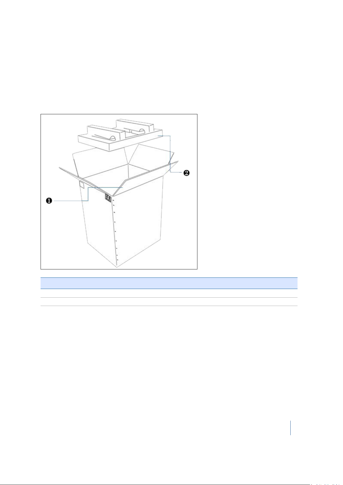
Shipping box
The TX8 3D scanner is packed inside an instrument case, and the instrument case is transported
inside a shipping box. The shipping box is a cardboard box with two foam pads—one on top and
one on bottom.
Item Description
❶ Flap
❷ Foam pads (x2)
To open the shipping box:
1. Open the seam by cutting the tape or staples.
2. Unfold the four flaps and then remove the top foam padding.
Note – Trimble recommends that you keep the shipping box and its foam padding in case you
need to transport the instrument; the box and foam padding provide additional safety for the
instrument. See Transporting the instrument, page 19.
Trimble TX8 3D Laser Scanner User Guide 11
Page 12
1 Introduction
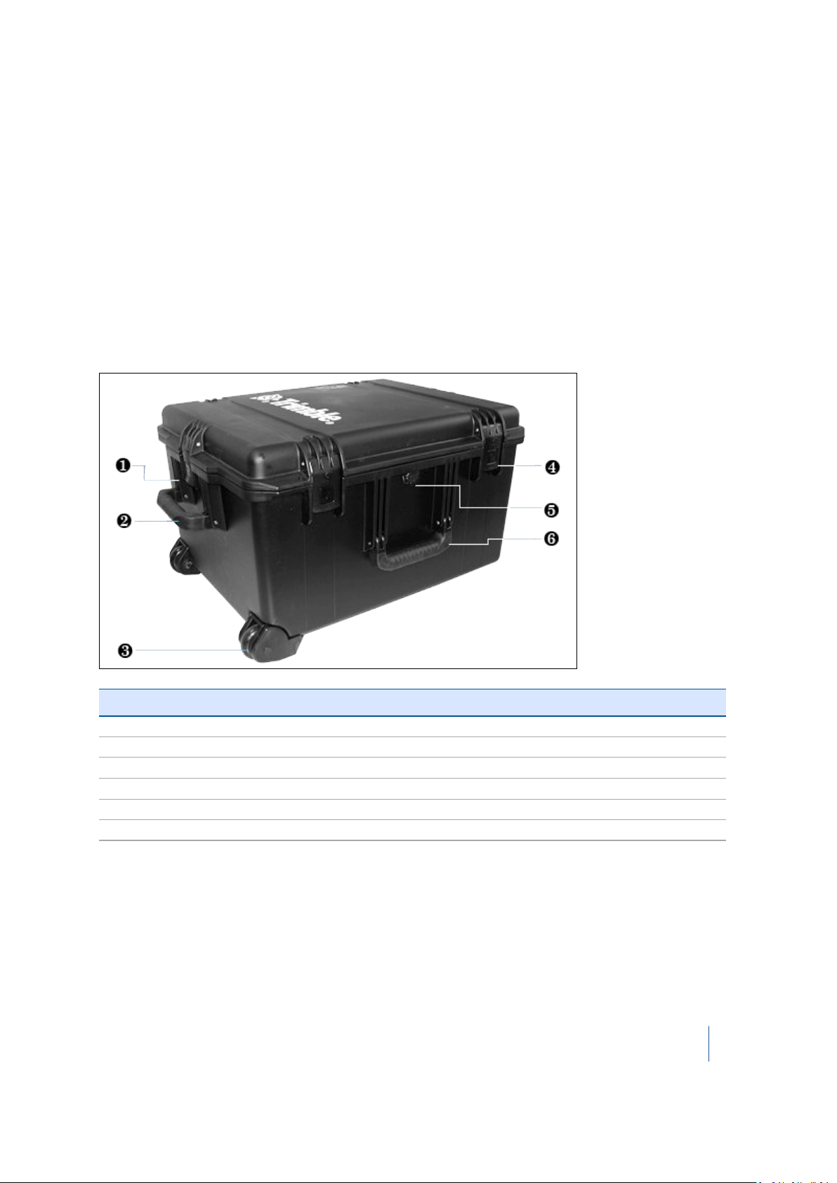
Instrument case
The instrument case is made of lightweight HPX resin. This is strong and durable and ensures a
watertight, airtight, dust-proof, chemical resistant and corrosion proof environment for the
scanner.
The case has a Vortex® valve on the front that can be used to equalize the atmospheric pressure
after quick changes. It also has heavy duty wheels with stainless steel bearings, telescoping handle,
and press and pull latches.
The TX8 3D scanner is fitted into a high-density foam mould that protects it against impact,
vibration, and shock.
Left/front side view
Item Description
❶ Press and pull latch
❷
❸ In-line wheel
❹ Press and pull latch (x 2)
❺ Auto-pressure release valve
❻ Double-layered, soft grip handle
Double-layered, soft grip handle
Trimble TX8 3D Laser Scanner User Guide 12
Page 13
1 Introduction
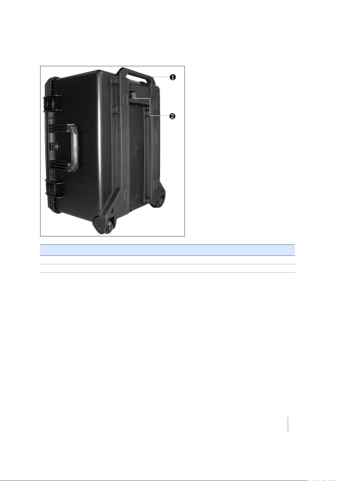
Bottom view
Item Description
❶ Retractable handle
❷ Lock for retractable handle
Inspecting the instrument case
If the instrument case is not in good condition, examine the items inside for visible damage. If any
items are damaged, immediately notify the carrier and your Trimble sales representative.
Keep the shipping box, the instrument case, and all packing material for the carrier to inspect.
Trimble TX8 3D Laser Scanner User Guide 13
Page 14
1 Introduction
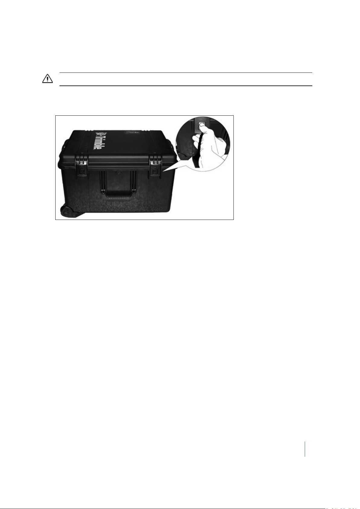
Opening the instrument case
CAUTION – Take care when removing the instrument from the case. Use proper lifting form for heavy objects.
1. Place the instrument case on the bottom side.
2.
Press and pull the four latches:
3.
Open the cover of the instrument case.
Trimble TX8 3D Laser Scanner User Guide 14
Page 15

1 Introduction
Items in the instrument case
Item Description
❶ Trimble TX8 3D scanner and tribrach
❷ Storage location for batteries (x4)
❸ Set of screen protectors
❹ Information disk (CD or DVD)
❺ Getting Started Guide
❻ Interchangeable adapter (x4)
❼ Power supply cable
❽ DC power supply
❾ Stylus pen kit
❿ USB flash drive
Trimble TX8 3D Laser Scanner User Guide 15
Page 16
1 Introduction
Item Description
⓫ Trimble stylus pen lanyard
⓬ Cleaning fluid
⓭ Lens tissues (pack of 50)
⓮ T3 adhesive targets (pack of 10)
Not shown Mirror cleaning cloth
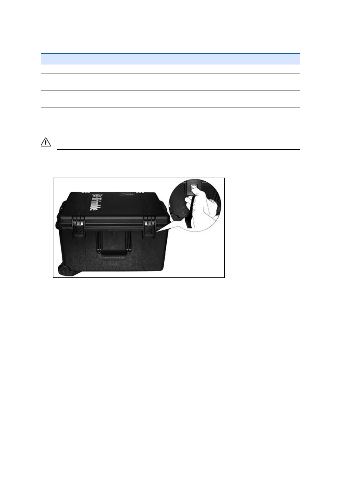
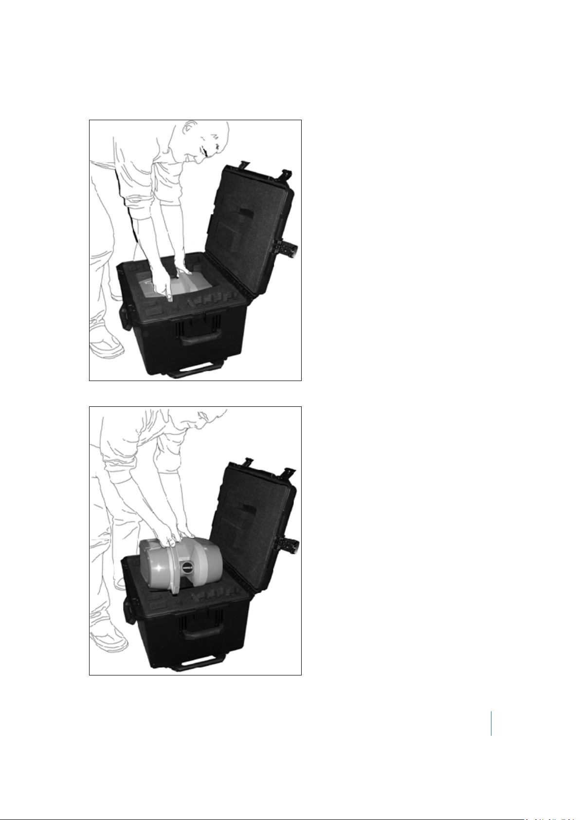
Remove the instrument from the case
CAUTION – Take care when removing the instrument from the case. Use proper lifting form for heavy objects.
1. Place the instrument case on the bottom side.
2.
Press and pull the four latches:
3.
Open the cover of the instrument case.
Trimble TX8 3D Laser Scanner User Guide 16
Page 17
1 Introduction
4.
With one hand, grasp the instrument handle, and then place the other hand on the base of the
instrument as shown:
5.
Lift the instrument assembly out of the case:
Trimble TX8 3D Laser Scanner User Guide 17
Page 18
1 Introduction
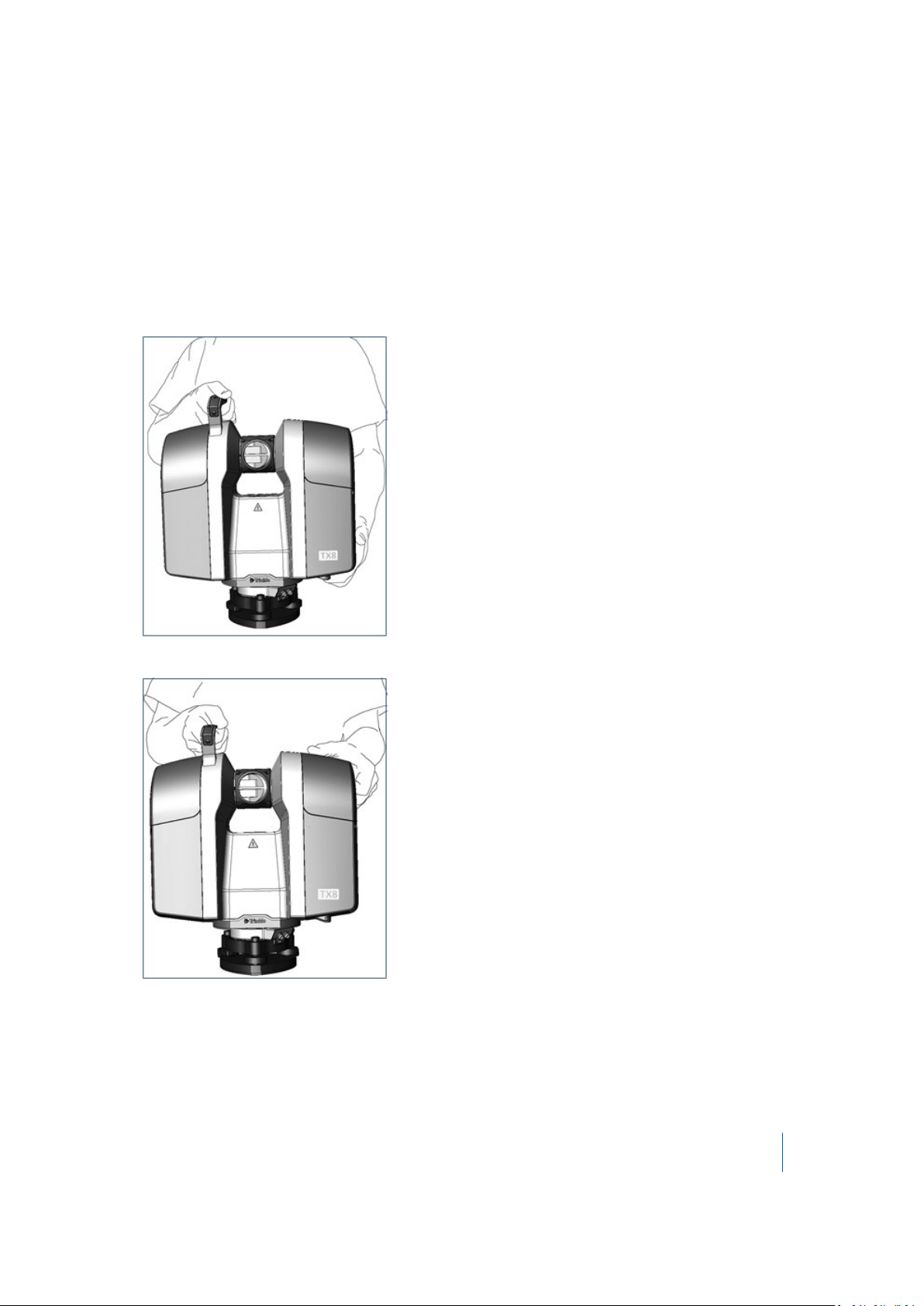
Lifting the instrument
To lift the instrument, there are two grips in addition to the handle:
l The upper grip is located near the top on the side opposite the main handle.
l The lower grip is located on the bottom of the scanner on the side opposite the main handle.
Use the method that you find most comfortable to lift the scanner. The options are:
l
With one hand, grasp the handle, and then grasp the upper grip with the other hand:
l
With one hand, grasp the handle and then grasp the bottom grip with the other hand:
Trimble TX8 3D Laser Scanner User Guide 18
Page 19

1 Introduction
Pulling the instrument case
CAUTION – Make sure that the instrument case is securely closed before carrying out this procedure.
You can pull the instrument case using the retractable pull handle.
a. Place the instrument case stood up on its left/front side.
b. Push and hold the lock to the right to release the telescoping handle.
c. Extract the telescoping handle to its full length.
d. Hold the telescoping handle firmly and tilt the box slightly so that it leans on its wheels.
Transporting the instrument
When transporting the instrument, Trimble recommends the following:
l Use the instrument case (or preferably, the instrument case inside the original shipping box
with the original foam padding blocks) to transport the instrument. The box(es) are designed to
protect the instrument against shock and vibration.
Ensure that the instrument case is completely closed before moving or carrying it.
l Fix a warning label, HANDLE WITH CARE, to the instrument case or shipping box.
Packing the instrument case into the shipping box
1. If required, assemble the shipping box—open the box, fold in the pair of flaps along the width
of the shipping box, fold in the pair of flaps along the length of the shipping box and then fasten
the seam with tape or staples.
2. Place a foam pad inside the shipping box.
3. Insert the instrument case (with all the items in place) into the shipping box.
4. Place the second foam pad on top of the instrument case.
5. Close the shipping box by folding in the flaps and then fastening the seam with tape or staples.
Care and maintenance
WARNING – DO NOT remove any covers from the instrument. This instrument is designed to withstand normal
electromagnetic disturbance from the environment but it contains circuits that are sensitive to static electricity. If
an unauthorized person opens the instrument cover, the function of the instrument is not guaranteed and the
warranty will be invalidated. The instrument is designed and tested to withstand field conditions, but like all
precision instruments, it requires care and maintenance. To get the best results from the instrument, take the
Trimble TX8 3D Laser Scanner User Guide 19
Page 20

1 Introduction
following steps:
– Do not subject the equipment to rough jolts or careless treatment.
– Keep the rotating mirror lens clean. Use only lens paper or other material that is designed for cleaning optical
equipment.
– Keep the instrument protected and in an upright position, preferably in the instrument case.
– Do not carry the instrument while the instrument is mounted on a tripod. Doing so can damage the tribrach
screws.
– Whenever manually rotating the instrument, use a slow and steady movement.
– Do not carry the instrument by the rotating mirror. Use the handle.
– When you need extremely precise measurements, make sure that the instrument has adapted to the
surrounding temperature. Significant variations in instrument temperature can affect precision.
Cleaning
CAUTION – DO NOT use strong detergents such as benzene or thinners on the instrument or the instrument case.
Be very careful when cleaning the instrument, especially when removing sand or dust from the
mirror lens. DO NOT use coarse or dirty cloth or hard paper. Trimble recommends that you use antistatic lens paper, a cotton wad, or a lens brush. To clean the exterior of the instrument, use a cloth
lightly dampened with water.
Removing moisture
If the instrument has been in damp weather, take the instrument indoors and remove the
instrument from the instrument case. Leave the instrument to dry naturally. If condensation forms
on the mirror lens, allow the moisture to evaporate naturally.
Technical support
If you have a problem and cannot find the information you need in the product documentation,
contact your local dealer. Alternatively, go to the Support area of the Trimble website
(www.trimble.com/support/). Select the product you need information on. Product updates,
documentation, and any support issues are available for download.
Related information
Sources of related information include the following:
l Release notes – The release notes describe new features of the product, information not
included in the manuals, and any changes to the manuals. They can be downloaded from the
Trimble website at www.trimble.com/support/.
Trimble TX8 3D Laser Scanner User Guide 20
Page 21

1 Introduction
l Trimble training courses – Consider a training course to help you use your instrument to its
fullest potential. For more information, go to the Trimble website at
www.trimble.com/support/index_training.aspx.
Trimble TX8 3D Laser Scanner User Guide 21
Page 22

CHAPTER
2
2 Instrument and Accessories
In this chapter:
n Instrument views
n Accessories
This chapter describes the instrument and its
controls. Trimble recommends that you take the
time to familiarize yourself with the names and
locations of the controls.
Trimble TX8 3D Laser Scanner User Guide 22
Page 23
2 Instrument and Accessories
Instrument views
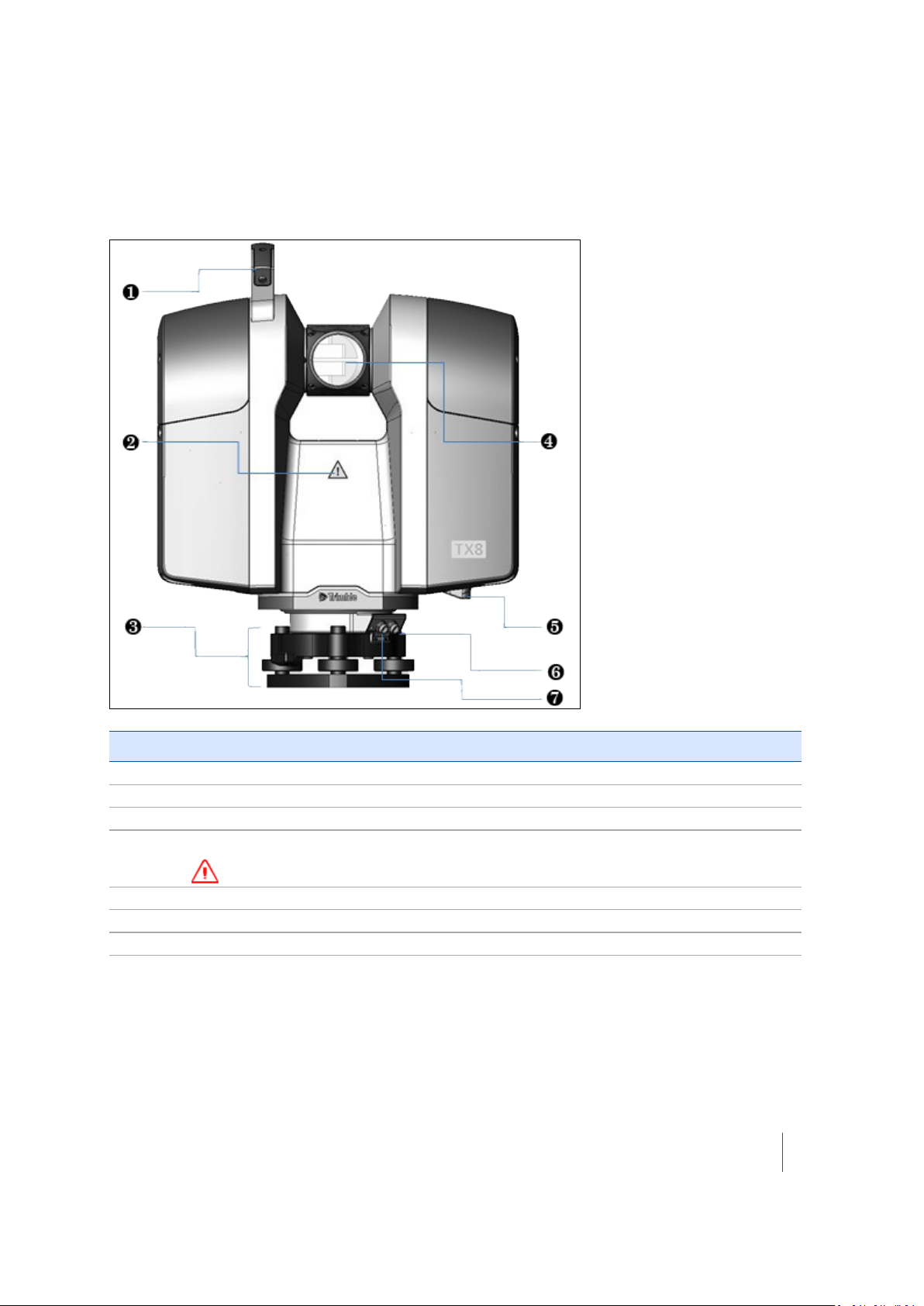
Front of instrument
Item Description
❶ Handle
❷
❸ Tribach
❹
❺ Bottom grip
❻ Power connector
❼ USB – Remote control connector
Hazard symbol label
Spinning mirror
WARNING – Stay clear of spinning mirror when in use.
Trimble TX8 3D Laser Scanner User Guide 23
Page 24
2 Instrument and Accessories
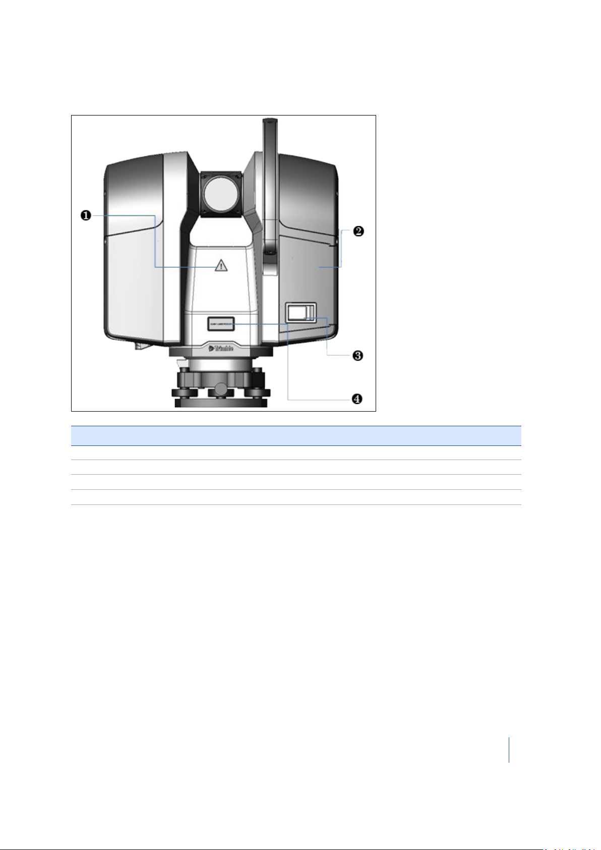
Back of instrument
Item Description
❶ Hazard symbol label
❷
❸ Door latch
❹ Laser warning label
Battery compartment door
Trimble TX8 3D Laser Scanner User Guide 24
Page 25
2 Instrument and Accessories
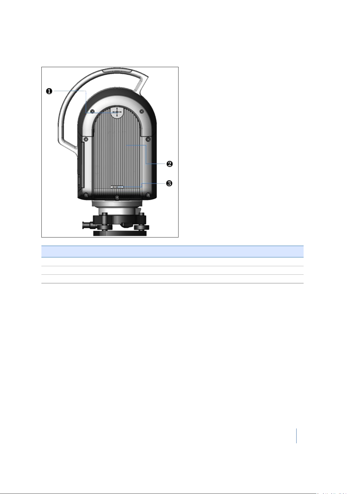
Left side of instrument
Item Description
❶ Top measurement mark
❷
❸ Bottom measurement mark
Instrument housing with integrated heat exchanger
Trimble TX8 3D Laser Scanner User Guide 25
Page 26
2 Instrument and Accessories
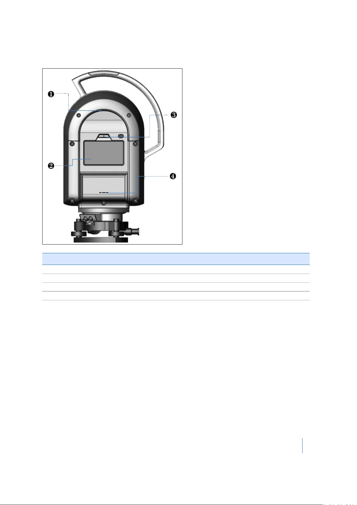
Right side of instrument
Item Description
❶ Top grip
❷
❸ On/Off key
❹ Instrument height measurement mark
Touch screen
Trimble TX8 3D Laser Scanner User Guide 26
Page 27
2 Instrument and Accessories
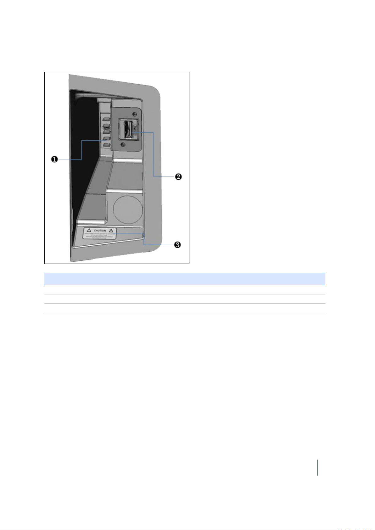
Battery/USB flash drive compartment
Item Description
❶ Battery connectors
❷
❸ Warning label
USB port
Trimble TX8 3D Laser Scanner User Guide 27
Page 28
2 Instrument and Accessories
Accessories
Trimble recommends that you take some time to familiarize yourself with the names and the
locations of the accessories.
Note – Trimble reserves the right to replace the illustrated units with an alternative item, without
prior warning.
External power supply kit
CAUTION – The power supply unit provided is for indoor use only. When using the instrument outdoors, please
use batteries for your power requirements.
The international power supply kit includes an external power supply, a power cable, and four
connectors (Europe, USA, UK, and Australia).
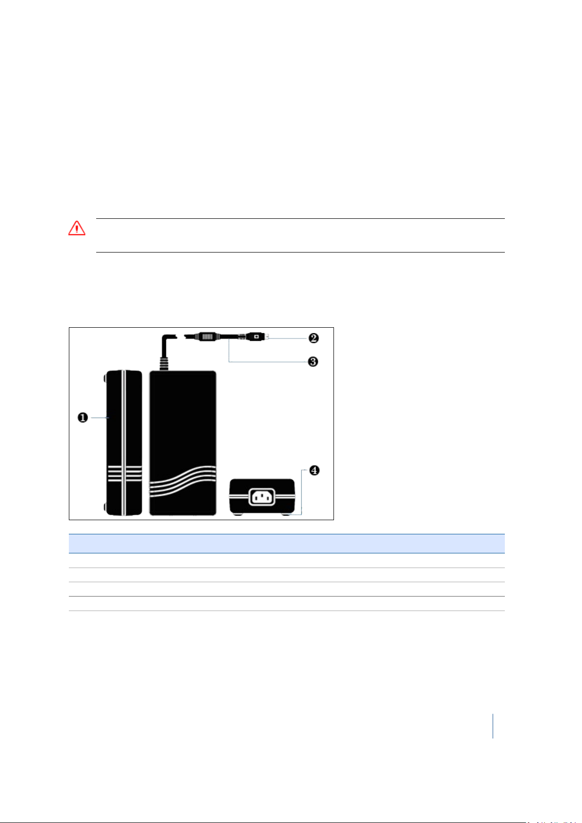
External power supply
Item Description
❶ External power supply
❷ 4-pin connector
❸ Power capable
❹ Rubber foot
See also External power supply specifications, page 95.
Trimble TX8 3D Laser Scanner User Guide 28
Page 29
2 Instrument and Accessories
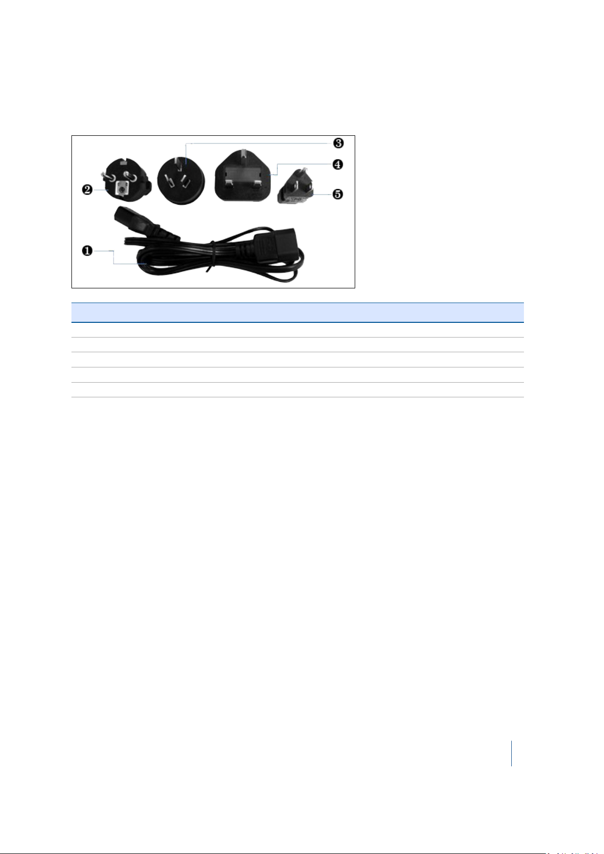
Power cable and connectors
The power cable and the four interchangeable connectors are provided in a zippered storage bag.
Item Description
❶ Power cable
❷ EU connector
❸ Australia connector
❹ UK connector
❺ USA connector
USB flash drive
Use the USB flash drive that comes with the instrument or one that is commercially available. If you
use a different USB flash drive, make sure that it is 64 GB or higher and formatted with FAT 32/16.
See also USB flash drive specifications, page 96.
Data acquired by your instrument is stored on the USB flash drive as well as the report resulting
from a diagnostic of the instrument. The USB flash drive is also used to update the firmware in the
instrument. See also Managing the USB flash drive, page 85.
Battery kit
For information on the battery kit, refer to the Trimble TX8 Battery Kit Quick Reference Card that
accompanies the instrument. See also Battery kit specifications, page 96.
Trimble TX8 3D Laser Scanner User Guide 29
Page 30
2 Instrument and Accessories
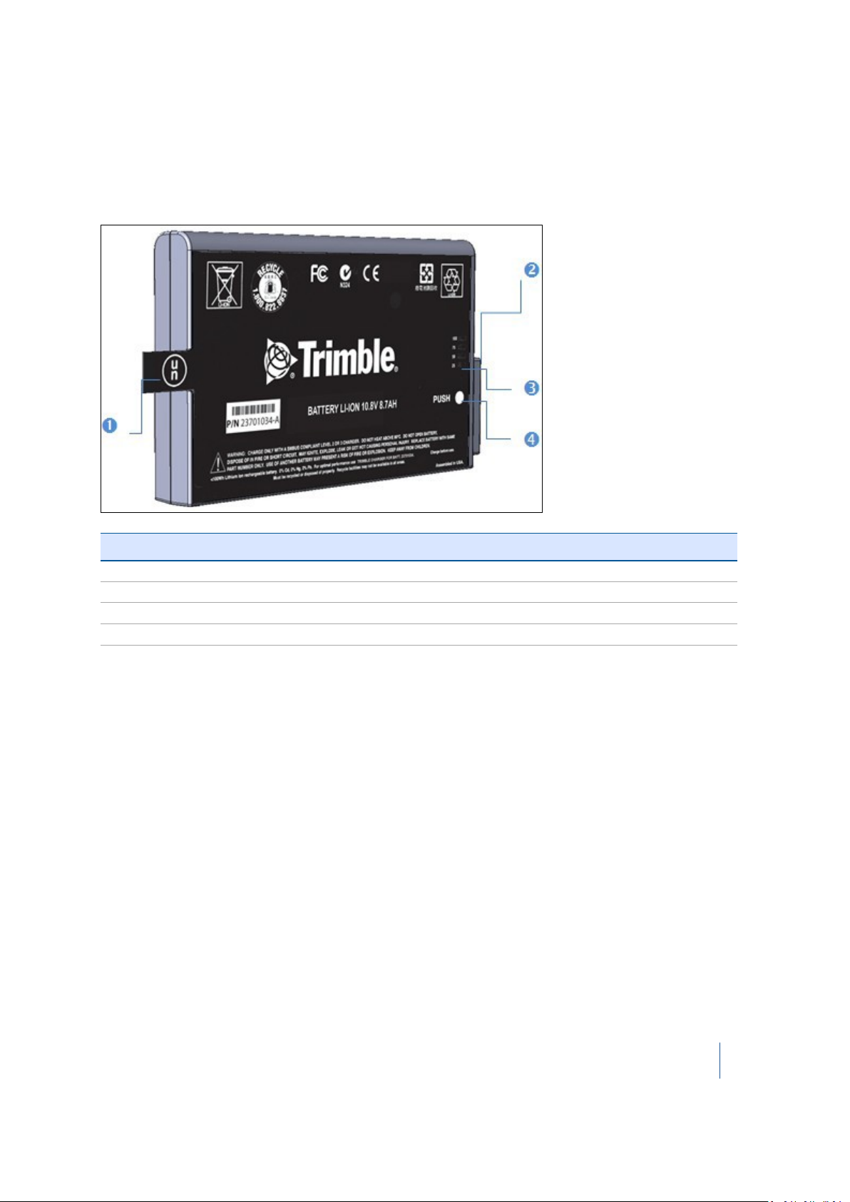
Smart battery
Before charging or using a smart battery it is important to read and understand the battery safety
and environment information included in the Safety chapter on page 4. See also Smart battery
specifications, page 96.
Item Description
❶ Flap
❷ Connectors
❸ Power gauge
❹ Button
Charging a smart battery
The smart battery is supplied partially charged. Please charge the battery completely before using it
for the first time. Charging takes approximately 4 hours per battery.
The two-bay charger is a smart charger. It can communicate with the battery in order to deliver the
appropriate charge. Each bay is independent. The charger can charge two batteries simultaneously.
1. Place the charger on a hard, flat and level surface to ensure that there is airflow under the
charger.
2. Plug the DC connector from the power supply unit into the back of the charger.
3. Plug the power supply cable to the external power supply.
4. Connect the other end of the power supply cable to a power supply network using an
interchangeable connector.
5.
Insert a battery into either bay ensuring that the 5-way connector is fully seated. All LEDs in the
status window will provide status information and the charger automatically starts charging.
Trimble TX8 3D Laser Scanner User Guide 30
Page 31

2 Instrument and Accessories
Checking the power level on a smart battery
Note – A battery with a poor power supply level may not be able to start the instrument (if it is
switched Off) and may switch Off the instrument (if it is switched On).
To check the power supply in a smart battery, do one of the following:
l Use the integrated battery gauge. Press the button on the battery to view the four LEDs on the
smart battery:
l
l Each LED corresponds to a power level of 25%. If the battery is fully charged, all LEDs are lit.
If it completely discharged, all are unlit.
l If all LEDs are flashing, the battery must be reconditioned in its charger.
l Check the level viewing the power supply icon on the touch screen with the instrument turned
on. This icon indicates the following charge states:
Trimble TX8 3D Laser Scanner User Guide 31
Page 32

2 Instrument and Accessories
Icon Charge Level
Less than 10%
Between 25% and 50%
Between 50% and 75%
Between 75% and 100%
Fully charged - 100%
Two-bay charger
The two-bay charger enables you to charge or recalibrate the fuel gauge on two batteries at the
same time. See also Two-bay charger specifications, page 97.
Item Description
❶ DC connector
❷ Fan outlet
❸ Battery bay
❹ Spacer (already inserted)
❺ Recalibration button
❻ Status window
Not shown External power supply
Connecting to the main power supply
1. Place the charger on a flat surface near an electrical outlet to ensure airflow under the charger.
2. Plug the AC/DC converter cable into the DC input connector on the rear of the charger.
Trimble TX8 3D Laser Scanner User Guide 32
Page 33

2 Instrument and Accessories
3.
Plug the power cable into the AC/DC adapter and into an electrical outlet via an
interchangeable connector. All the LEDs will flash momentarily to let you know that power is
present:
LED behaviors
There are two LED indicators behind the status window, one for each battery bay. Both indicate
battery status.
If the icon is … then …
green, flashing the battery is charging.
green, solid
blue, flashing the battery is in calibration mode.
blue, solid the battery fuel gauge has been calibrated.
red, flashing the battery fuel gauge is in need of recalibration.
red, solid there is an error.
the battery is fully charged.
Trimble TX8 3D Laser Scanner User Guide 33
Page 34

2 Instrument and Accessories
Tribrach
The tribrach that comes with the instrument is equipped with a bull's-eye bubble for leveling and a
built-in optical plummet for precise setting up over a survey point. See also Tribrach specifications,
page 97.
The instrument is also equipped with an internal electronic level and dual-axis compensator. See
Leveling, page 68.
Item Description
❶ Eye piece
❷ Focusing ring
❸ Cross-hair ring
❹ Clamping arm
❺ Circular bubble level
❻ Foot screw (x3)
Micro fiber lens cleaning cloth
A micro-fiber lens cleaning cloth is included. See Micro fiber lens cleaning cloth specifications, page
97.
Stylus pen kit
The stylus pen kit is composed of two styluses and one tether.
Trimble TX8 3D Laser Scanner User Guide 34
Page 35

2 Instrument and Accessories
TX8 USB external cable
The Trimble TX8 USB External Cable is a cable of 2.8 meters.
It enables you to connect your Trimble TX8 3D scanner to a remote device that should have the
following requirements.
Remove device system requirements
Remote Device Microsoft Windows™ PC or tablet running Windows 7 Home Premium or
later
Cable
Drivers
VNC Client
Note – The Trimble TX8 USB external cable is an optional cable that must be purchased separately.
Trimble reserves the right to replace the illustrated unit with an alternative item, without prior
warning.
Note – Microsoft Windows™ RT or Windows™ Mobile/Phone OS is not supported.
Part Number 23704034 - TX8 USB Cable 2.8 Meters
Tablets with MicroUSB ports require an OTG to USB adapter
LAN 9500 drivers for Windows x86 and x64
Download Trimble TX8 LAN 9500 Drivers
RealVNC Viewer for Windows x86 and x64
Download Trimble TX8 RealVNC Viewer
Trimble TX8 3D Laser Scanner User Guide 35
Page 36

CHAPTER
3
3 Setup
In this chapter:
n Setting up the tripod
n Setting up the instrument
n Settling down the instrument on the
tribrach
n USB flash drive
n Powering the instrument
n Turning the instrument on and off
n Connecting the instrument to a remote
device
n Changing the default settings
n Measuring the instrument heights
Organize all the items from the instrument case
and take them to where you want to collect the
data.
Once you have done this, you can set up the
different parts and turn them on for use.
If you want to use the instrument in a survey
workflow, you will need a control point, which is
required for setting up the instrument.
This control point becomes the first site point for
data collection. Be sure you know its coordinates
and identifier. Set up the instrument on the tripod
over the control point and then visually locate a
second point called the backsight point. The
direction from the control point to the backsight
point will indicate where you need to direct the
instrument.
Trimble TX8 3D Laser Scanner User Guide 36
Page 37

3 Setup
Setting up the tripod
1. Spread the three legs of the tripod.
2. Unscrew the screw lock at the bottom of each leg.
3. Extend the three legs as far as required.
4.
Tighten the screw lock at the bottom of each leg.
Note – The three legs must be set wide enough apart to increase the stability of the setup. If it
is not possible to set the legs wide apart, consider lowering the tripod. However, the height of
the tripod must allow the instrument to be effectively mounted.
5. Position the tripod over the control point on flat and stable ground where possible.
6. Visually check that the tripod plate is as horizontal as possible.
CAUTION – To avoid the tripod tipping over and damaging the instrument, ensure that the ground is stable when
installing the tripod. Do not push the legs into the ground because you may need to adjust the tripod position.
Setting up the tribrach
Your TX8 instrument is supplied with a tribrach mounted on it. Remove it from the instrument
before performing the steps below.
1. Remove the rubber cover from the tripod head.
2. Stand a few paces from the tripod.
3. Visually check that the tripod is set up so that the tripod plate is as horizontal as possible.
Trimble TX8 3D Laser Scanner User Guide 37
Page 38

3 Setup
4.
Place the tribrach in a central position on the plate of the tripod.
Note – When placing the tribrach on the tripod plate, ensure that you align the foot screws
with the tripod legs.
5. Secure the tribrach with the central fixing screw.
Leveling the tribrach
1.
Turn two of the foot screws together in opposite directions. The bubble should move from
right to left and vice versa.
2. Move the bubble into the center of the circular bubble level.
3. Turn the third foot screw. The bubble should move from forward to backward and vice versa.
4.
Move the bubble into the center of the circular bubble level.
Trimble TX8 3D Laser Scanner User Guide 38
Page 39

3 Setup
Centering over a known point
If the tribrach supplied with your TX8 scanner comes with an optical plummet, perform the steps
below.
1.
Look through the optical plummet eyepiece on the tribrach.
2.
Rotate the cross-hairs ring on the eyepiece until the cross-hairs appear clear, then rotate the
focusing ring on the eyepiece to focus on the control point.
3. Look again through the optical plummet eyepiece. If the cross-hairs are not exactly over the
control point on the ground, do one of the following:
l l Move the tripod to align the cross-hairs with the control point.
Trimble TX8 3D Laser Scanner User Guide 39
Page 40

3 Setup
l Lightly unscrew the central fixing screw below the tripod to move the tribrach. Look
through the eyepiece and align the cross-hairs with the control point and then secure the
fixing screw.
l Lightly unscrew the screw locks on the tripod, extend or retract the three legs to align the
cross-hairs with the control point and then secure the screw locks.
4. Stand a few paces from the tripod and visually check that the tripod head is still horizontal.
5. Visually check again that the bubble is still in the center of the circular bubble control level.
6. When satisfied, secure the tripod by pushing the legs into the ground.
Setting up the instrument
Set up your instrument on the tripod using the following steps.
1. Place the instrument over the tribrach.
2.
Align the instrument studs with the foot screws of the tribrach:
3. Firmly insert the instrument into the tribrach.
4. Secure the instrument with the tribrach clamping arm.
Trimble TX8 3D Laser Scanner User Guide 40
Page 41

3 Setup
Settling down the instrument on the tribrach
Note – In some cases, you may need to manually move the instrument slightly in the tribrach from
left to right and vice versa as illustrated in order for the scanner to settle completely in the
tribrach’s locking system so it is stable before tightening the clamping arm on the tribrach.
Trimble TX8 3D Laser Scanner User Guide 41
Page 42

3 Setup
USB flash drive
The USB flash drive needs to be inserted in the instrument for data storage. You can use the USB
flash drive that comes with your instrument or one that is commercially available.
Inserting the USB flash drive
1. Release the latch of the battery compartment door.
2. Open the battery compartment door.
3.
Insert the USB flash drive into the USB slot:
4. Close the battery compartment door.
Once the USB flash drive has been inserted into the USB port, and once the instrument is switched
on, the following icons appear on the touch screen:
If the icon .... it indicates that the USB flash drive ....
is black, with a number
beside it
is red and blinking is missing, full, or needs to be formatted.
has been inserted into the instrument. The number corresponds to
the number of scans the USB flash drive can store, which changes if
you change the scan settings. See
Trimble TX8 3D Laser Scanner User Guide 42
Scan parameters, page 72
.
Page 43

3 Setup
Removing the USB flash drive
CAUTION – DO NOT remove the USB flash drive from the instrument while it is scanning, running a firmware
update, or processing a diagnostic test.
1. Release the latch of the battery compartment door.
2. Open the battery compartment door.
3. Remove the USB flash drive from the USB slot.
4. Close the battery compartment door.
Trimble TX8 3D Laser Scanner User Guide 43
Page 44

3 Setup
Powering the instrument
You can use a battery or an external power supply to power the instrument. Both options are
provided.
If you insert a battery into the instrument while it is connected to an external power unit, the
battery will be used as the primary power supply (if the battery is fully charged). When the battery
charge level drops to 60%, the external power supply takes over.
Using an external power supply
CAUTION – Remove the instrument from the tripod prior to transport. Do not move the instrument while
connecting or disconnecting the external power supply.
1. Remove the rubber cap from the 12 V power connector that is on the front side of the
instrument.
2. Align the red dot at the LEMO connector of the power supply cable with the red mark at the 12
V power supply connector.
3. Firmly insert the LEMO connector into the 12 V power supply connector.
4. Plug the power supply cable to the external power supply.
5.
Connect the other end of the power supply cable to a power supply network using an
interchangeable connector:
Note – Use the interchangeable adapter suited to your power supply network.
Trimble TX8 3D Laser Scanner User Guide 44
Page 45

3 Setup
Note – Use a circuit-breaker (not supplied) between the external power supply and the power
supply network to protect your equipment against voltage fluctuations.
Note – Once the instrument is turned on, on the touch screen either the Battery icon appears if
there is fully charged battery installed, or the Power Supply icon appears indicating that the
external power supply is being used.
Inserting a battery
The smart battery fits into the battery compartment on the back of the instrument. It can be easily
removed and replaced.
1. Ensure that the instrument is turned off.
2. Release the latch of the battery compartment door.
3. Open the battery compartment door.
4.
Insert the battery into the battery compartment with the battery connectors positioned
towards the bottom of the instrument:
5. Close the battery compartment door.
Note – Once the instrument is switched on, the power supply icon on the touch screen indicates
that the instrument is powered by battery.
Trimble TX8 3D Laser Scanner User Guide 45
Page 46

3 Setup
Removing a battery
CAUTION – DO NOT remove the battery from the instrument while it is scanning, running a firmware update, or
processing a diagnostic test.
1. Ensure that the instrument is turned off.
2. Release the latch of the battery compartment door.
3. Open the battery flap.
4.
Remove the battery from its slot. If required, you can use the tab to help you do this:
5. Close the battery compartment door.
Trimble TX8 3D Laser Scanner User Guide 46
Page 47

3 Setup
Turning the instrument on and off
Turning on the instrument
To turn on the instrument, press and hold the On/Off key for at least three seconds.
The LED on the On/Off key first lights up accompanied by a beep indicating that the instrument is
starting up.
After the instrument has started, the LED stops blinking and stays illuminated in green. The main
menu appears on the touch screen (see Software (page 52)):
Note – To ensure the best performance it is important to first let the instrument warm up. To do
this simply perform a Level 2 scan in the environment where the scanning will take place. See
Choosing a scan mode, page 73.
Turning off the instrument
To turn off the instrument, press and hold down the On/Off key.
Trimble TX8 3D Laser Scanner User Guide 47
Page 48

3 Setup
Connecting the instrument to a remote device
1. Remove the rubber cap from the USB connector at the base of the instrument.
2. Align the red dot on the LEMO connector of the TX8 USB cable with the red mark on the TX8
USB connector.
3. Firmly insert the LEMO connector into the TX8 USB connector.
4.
Insert the USB connector of the TX8 USB cable into the USB connector on the Windows PC or
tablet, for example, a Trimble Yuma tablet (illustrated below):
5.
Turn on the instrument. If your remote device is connected to the Internet, the appropriate
LAN9500 driver should automatically download and install:
Trimble TX8 3D Laser Scanner User Guide 48
Page 49

3 Setup
6.
If you do not have Internet access, use the link below to download the LAN9500 executable and
manually install the driver.
LAN 9500 drivers
7.
Use the link below to download the VNC Viewer and copy either the 32-bit or 64-bit version to
your device.
RealVNC Viewer
8.
Double-click the VNC Viewer executable to run the program.
9.
Configure the VNC Server with the IP address of 192.168.42.1 as shown and then click Connect:
10.
The Trimble TX8 user interface will display on your remote device for remote operation of the
instrument.
Note – Remote devices with Micro USB ports require an OTG-to-USB adapter.
Changing the default settings
The instrument has factory default settings for date, time, and unit of measurements. Before using
the instrument, you should change these to meet your requirements. See Setting the date and time
(page 84) and Selecting the measurement units (page 85).
Trimble TX8 3D Laser Scanner User Guide 49
Page 50

3 Setup
Measuring the instrument heights
The Instrument Height (IH), also called True Vertical, is the distance between the Known Point used
during instrument setup and the centre of the mirror. As this centre is not accessible, two
measurement marks are on the left side of the instrument and one on its right side.
The Top Mark ❶ corresponds to the Trunnion Axis of the instrument. The Bottom Mark ❷ is
0.184 m below the Top Mark. The Bottom Mark is at a distance of 0.1675 m from the center of the
instrument.
Trimble TX8 3D Laser Scanner User Guide 50
Page 51

3 Setup
Measuring the ground-to-bottom mark distance
Measure the distance which separates the Known Point on the ground to the Bottom Mark on the
side of the instrument. This measured distance will be called Hm (or Bottom Mark). To obtain the
True Vertical value, please use the formula given hereafter.
Computing the instrument height (IH)
To calculate the Instrument Height (IH), please insert the measured distance (Hm) into the formula
below:
The Hm distance is corrected to obtain a vertical measurement to the Bottom Mark. This vertical
measurement is called (Hc). The distance from the Bottom Mark to the Top Mark is added to the
(Hc) to obtain the Instrument Height from the Known Point to the Trunnion axis (Ih).
Trimble TX8 3D Laser Scanner User Guide 51
Page 52

CHAPTER
4
4 Software
In this chapter:
n Touch screen
n Projects
n Leveling
n Scan parameters
n Settings
This chapter explains how to change the settings in
the software to suit your needs.
Trimble TX8 3D Laser Scanner User Guide 52
Page 53

4 Software
Touch screen
The touch screen is a resistive screen. You can use either your finger, or the stylus that comes with
the instrument to access the software settings and to perform scans.
1 Trimble icon 4 Approximate remaining battery power
2 Current project 5 High contrast icon
3 Number of scans that can be stored in
the USB flash drive using the current
scan settings
When powering the instrument with the USB flash drive missing, a dialog appears and prompts you
to insert a USB flash drive. The USB Flash Drive icon flashes red. The message No USB Flash Drive
appears next to the Trimble icon and there is no station name in the "Station" line.
Once an USB flash drive has been inserted into the USB port of the instrument, the dialog closes.
The message NO USB Flash Drive disappears. The red and flashing USB Flash Drive icon stops
flashing. It becomes white and displays the number of scans (based on the current settings) that it
can store.
Note – The dialog only appears when the instrument starts. When unplugging the USB flash drive
from the instrument while it is already powered on, only the USB flash drive icon flashes red and
the message NO USB Flash Drive appears next to the Trimble icon.
Note – If the USB flash drive is missing, some features of the software are disabled. Selecting these
features causes the screen to re-appear.
6 Current scanning settings
Trimble TX8 3D Laser Scanner User Guide 53
Page 54

4 Software
Projects
When you insert a new or an empty USB flash drive into the instrument, a new project is
automatically created. By default, it is named "Project XXX" where XXX starts at 001 and increments
by one digit each time a new project is created.
If there is no project available on the USB flash drive when turning on the instrument, a new empty
project is created using the name of the last scanned project and starting with "Station 001". If there
is a project stored on the USB flash drive, the last modified project is automatically loaded.
A project folder named "Project XXX" is created under the root of the USB flash drive. Under that
folder, a RealWorks project file with an RWP file extension is also created.
1.
From the main menu, tap . The projects dialog appears:
2.
In this dialog, you can:
l l manage projects. See page 55.
l manage stations. See page 58.
l manage scans. See page 60.
Note – If there is no USB flash drive in the instrument when tapping the Projects button , a
dialog appears and prompts you to insert one.
Trimble TX8 3D Laser Scanner User Guide 54
Page 55

4 Software
Managing projects
Projects can be created, opened, edited, and deleted.
Creating a project
1.
From the Projects menu, tap . The Create new project dialog appears:
2.
In the New Project Name panel, tap Change. The Project name dialog appears. Enter a name
for the project and then tap OK.
The name for the next project is the current (or last) project with an increment. This increment
can be either a number or a letter. For example, if the last character for the current project is 8,
it will be then 9. If it is a S, it will be then a T, and so on. The name can be composed of letters,
numbers, and characters. Some characters are forbidden, which are dimmed on the keyboard.
3.
In the Operator Name panel, tap Change. The Operator name dialog appears. Enter the name
of the operator and then tap OK.
If an operator name has been entered for the current project, this name is then used for the
next project and it is displayed in the panel. If there is no operator name, the Operator Name
panel is blank. The name can be composed of letters, numbers, and characters. The Operator
Name is reset to blank when you reset your Personal Settings.
4. Tap Save. The Create New Project dialog disappears.
A project folder named Project XXX is created under the root of the USB flash drive. Under that
folder, a RealWorks project file with an RWP file extension is also created.
Trimble TX8 3D Laser Scanner User Guide 55
Page 56

4 Software
Opening a project
1.
From the Projects menu, tap . All projects are listed in order of creation:
2. For each project, you can view the following information:
l l Project name.
l Number of stations – Operator name.
l Day/Month/Year and time of creation between parenthesis.
3.
Tap next to the project that you want to open. All stations in the project are listed. See
Managing stations, page 58.
CAUTION – Once you open and save a project in the Trimble RealWorks software, you will no longer be able to
open it on the TX8 scanner. It disappears from the projects list after you tap the Open Projects icon .
Deleting a project
1.
From the Projects menu, tap . The icon turns yellow and a Delete icon appears next to
each project except for the current open project. You cannot delete an open project.
2.
Tap next to the project that you want to delete. A dialog prompts you to confirm the
operation.
3. Tap Yes.
CAUTION – Deleting a project deletes the related project file (with an RWP extension) and folder (with an RWI
extension) as well as all scans in the project.
Trimble TX8 3D Laser Scanner User Guide 56
Page 57

4 Software
Editing a project
1.
From the Projects menu, tap . The Edit current project dialog appears:
2. In this dialog, you can:
l l Rename the current project.
l Change the operator name.
3. Tap Save. The Edit Current Project dialog closes.
To rename the current project:
1. In the Current Project Name panel, tap Change. An on-screen keyboard appears with the
current name highlighted.
2. Enter another name and then tap OK. The Edit current project dialog appears.
3. Tap Save.
The Trimble RealWorks project file (with an RWP extension), the project folder (with an RWI
extension), and the folder which contains both of the files are also renamed. If there is a TZF format
file in the RWI folder, the project name (of the file) is also renamed.
To change the name of the operator in the current project:
1. In the Operator name panel, tap Change. An on-screen keyboard appears with the current
name highlighted.
2. Enter another name and then tap OK. The Edit current project dialog appears.
3. Tap Save.
Note – The Operator name is reset to blank when you reset your Personal settings (see page 91).
Trimble TX8 3D Laser Scanner User Guide 57
Page 58

4 Software
Managing stations
After tapping the Projects icon, the current project opens automatically. If the project is empty, the
message "This project is empty" appears. If it is not, all stations for that current project are listed:
Stations are listed in order of creation. A station is simply a container. For each station, verify the
following information:
l The instrument height.
l The number of Full scans.
l The number of Area scans.
l The Day/Month/Year and time it was created.
l A thumbnail image.
Creating a station
Each time a scan is performed, a new station is automatically created. By default, each station is
named "Station XXX", where XXX starts at 001 and increments by one digit each time a new station
is created. You cannot manually name a newly created station; you must use the default one.
The number between the parenthesis next to the USB flash drive icon on the main menu decreases
each time a new station or scan is created. At the same time, a TZF format file is created and placed
in the RealWorks project folder (named Project XXX.rwi). The TZF format file is: Project XXX_Station
XXX_Scan XX.tzf. If the current project is empty (no stations), the RealWorks project folder is
automatically created.
The current station name is shown in the title bar:
Trimble TX8 3D Laser Scanner User Guide 58
Page 59

4 Software
Tip – The name on the main menu is the name of a new station:
Deleting a station
Deleting a station deletes all the scans associated with that station.
1.
Tap . A Delete icon appears next to each station, in place of the thumbnail.
2.
Tap next to the station that you want to delete. A dialog appears and prompts you to
confirm the deletion. Tap OK.
CAUTION – You may see that the station is removed from the list on the touch screen. The "Project XXX_Station
XXX_Scan XX.TZF" file(s) that is related to the deleted station is also removed from the RealWorks project folder
(with an RWI extension) on the USB flash drive. Wait a while, otherwise, the file(s) will not be deleted from the
USB flash drive.
Trimble TX8 3D Laser Scanner User Guide 59
Page 60

4 Software
Managing scans
When you tap the station's thumbnail, all scans for that station are listed. Scans are listed in order
of creation. For each scan, you can view the following information:
l Type: "Full" or "Area".
l Mode of acquisition: Preview, Level 1, Level 2, Level 3, or Extended (if the Extended option is
installed). See page 73.
l Mode of precision: One Pass or HP – 4 Passes. See page 75.
l Instrument Height value.
l The Day/Month/Year and time of creation.
l The thumbnail preview of the image to be scanned.`
Creating a scan
By default, a scan is a 360° acquisition of 3D coordinate data, also known as a "Full scan". If you
want to acquire data on a smaller area, this is called an "Area scan".
Each scan is named "Scan XX" where XX is its order. XX starts at 01 and increments by one digit for
each new scan. You cannot give a name to the newly created scan other than the default one. For
each scan, a TZF format file is created and placed in the RealWorks' RWI folder. It is named: Project
XXX_Station XXX_Scan XX.
Note – The current scan name does not appear on the title bar as for a project or a station.
CAUTION – When moving to a new station you must return to the Home menu and start the scan from there. All
scans performed from the Scan Display menu are associated with that station.
Acquiring a full scan
1.
From the main menu (or in the Scanning panel of the Leveling dialog), tap . The
instrument performs an initialization. It rotates around its vertical axis to find its zero position.
Once done, data acquisition starts and a progress bar appears.
Note – If the USB flash drive is full, a dialog appears only after tapping Scan.
2.
Select a condition specified in the following table. This condition combines the Compensator
feature and the Auto Level Check function with the Leveling state of the instrument.
Trimble TX8 3D Laser Scanner User Guide 60
Page 61

4 Software
Instrument leveling Disable compensator Auto level check Instrument leveling
Out of Range Unchecked Unchecked Enabled
Unleveled
Leveled
Out of Range Checked Disabled
Unleveled
Leveled Enabled
Out of Range Checked Unchecked Enabled
Unleveled
Leveled
Out of Range Checked
Unleveled
Leveled
3.
You can interrupt the acquisition in progress by tapping Stop.
4.
You can pause and resume the acquisition in progress by tapping Pause or wait until it finishes.
5.
On completion of the operation, the acquired data is written to the USB flash drive and a visual
of the scan appears:
Note – If there is no USB flash drive in the instrument when tapping the Scan icon, a message
appears and prompts you to insert one.
Trimble TX8 3D Laser Scanner User Guide 61
Page 62

4 Software
Tip – On the scan display screen, the Scan icon is always enabled. By tapping it, you can acquire another Full
scan or perform an area scan. You can check that you are still in the Full Scan acquisition mode in the next
step (after tapping on the Scan icon) as the next page name is Full Scan and the framing area is indicated as
0° to 360°.
Note – When resetting the Personal Settings, the Area scan density defaults to the last setting
used.
CAUTION – A warning message appears at the end of the acquisition if the instrument position has changed
before, between, or after the scanning.
Once a full scan is complete, you have the option to perform another full scan within the same
station or perform a scan of a specific area (known as an Area scan) or change the Instrument
Height.
Changing the Instrument Height
If your instrument has been initially leveled (green bubble) and the Compensator enabled, you are
able to change the Instrument Height you previously set.
1.
From the scan display screen, tap and then tap . The Instrument height screen
appears:
The keyed-in value displayed in the Instrument height pane and the Measurement method are
those set in the Scan Parameters dialog.
2. Tap Change and the on-screen keyboard appears.
3. Enter the new value. You can add numbers that include a decimal point.
4. Tap OK. The on-screen keyboard disappears. The input value is shown in the Instrument height
panel as well as the corrected value (obtained according to the formula given in the Setup
chapter).
5. If required, tap the pull-down arrow and change the current method.
6.
Tap to return to the scan display dialog or tap to return to the main menu.
Trimble TX8 3D Laser Scanner User Guide 62
Page 63

4 Software
Note – If the instrument has not been initially leveled (the bubble is yellow in the Leveling window)
or when it has been leveled (the bubble is green) but the Compensator is disabled , the IH icon
is grayed out.
Note – If you turn off the instrument or remove the USB drive from the instrument after a scan the
Measurement method and the value you entered for the Instrument height are not saved in the
project file. When you load that scan, the Instrument height dialog appears showing only the
calculated value and the true height (the height from the point on the ground to the center of the
instrument), as shown below.
Acquiring an area scan
You can only add an area scan to the last scan.
1.
From the scan display screen, tap and then tap the Area Scan icon . The Area Scan
icon is highlighted in yellow and two vertical red lines show the boundary of the area to be
scanned:
The default size of the scan area is one-third the size of the Full scan display. Areas that are
shaded blue are not scanned.
Trimble TX8 3D Laser Scanner User Guide 63
Page 64

4 Software
2. Define a scan area:
a.
Tap on a vertical line to drag it into position. When selected, the vertical line turns green.
Drag the vertical lines to position the boundaries of the scan.
Tip – To return to Full scan mode for the current station, tap again to remove the vertical lines.
o
o
Tap . The Area scan dialog appears:
3. Set the mode of the scan. See page 73.
The Mode parameter in this dialog may differ from the Mode parameter in the Scan
Parameters dialog. For this reason, the number of scans that the USB flash drive can store may
change.
4.
Set the parameter of the scan by tapping . See Scan parameters, page 72
5.
Tap .
Performing an additional area scan
Do one of the following:
l
Tap and then tap the Area Scan icon .
l Redefine the area to be scanned using the vertical bars.
l
Tap the Scan button to view the Area scan dialog.
l
Tap the Scan button .
Trimble TX8 3D Laser Scanner User Guide 64
Page 65

4 Software
Canceling a scan
1. Tap Stop.
2.
Either tap or to return to the main menu. A message appears asking whether or
not you want to return the instrument to its origin.
3. Tap Yes. The instrument rotates to be positioned to its origin.
Note – A TZF file is created even if the scan has been interrupted.
Pausing and resuming a scan
1.
Tap to pause the scan in progress:
A countdown begins with a time of 2 minutes.
2.
Tap to resume the scan in progress:
3.
If you do not resume the scan before the end of the countdown, it is canceled and saved.
A dialog appears asking if you want the instrument to return to its origin or not.
4. Tap Yes. The instrument rotates to be positioned to its origin.
Trimble TX8 3D Laser Scanner User Guide 65
Page 66

4 Software
5. Tap Cancel. The dialog closes.
6.
Either tap or to return to the main menu.
Note – A single TZF file is created even no matter how many times the scan has been interrupted.
Deleting a scan
1.
Tap . A Delete icon appears next to each scan, in place of the thumbnail.
2.
Tap next to each scan you want to delete. A dialog appears and prompts you to confirm
the deletions.
3. Tap OK.
CAUTION – Deleting a scan also deletes the related TZF file from the RWI folder on the USB flash drive.
Trimble TX8 3D Laser Scanner User Guide 66
Page 67

4 Software
Viewing a scan
1. If required, open a project.
2. In the list of stations, tap on a station thumbnail beside the station to load.
3.
In the list of scans, tap a thumbnail image corresponding to the scan to be opened. The Lpic
related to the loaded scan appears:
Note – If you leave the displayed Lpic by tapping , this returns you to the main menu. If
you tap the Projects icon, this will not display the list of stations but the list of scans.
Zooming In
Tap .
Zooming out
After zooming in, the Zoom Out button becomes enabled. To zoom out, tap .
Panning
Drag and drop the scan data in a given a direction to pan it in that direction.
Trimble TX8 3D Laser Scanner User Guide 67
Page 68

4 Software
Leveling
Leveling an instrument is the action of adjusting its vertical position using the three leveling screws
of the tribrach located below the instrument. The electronic bubble in the Leveling dialog provides a
visual control to check whether or not the instrument is leveled. It may have three states: Out of
Range (not visible), Yellow, or Green.
In addition to the electronic bubble, the Leveling dialog displays the Trunnion and Sighting
information. The horizontal rotation's axis of the instrument is called Trunnion, while its sighting
direction for acquiring cloud data is called Sighting. Both are expressed in degrees, minutes, and
seconds. When activated, the Compensator will automatically level-compensate all 3D points.
Checking the leveling status of the instrument
1.
From the main menu, tap . The Leveling dialog appears.
When the instrument is leveled, the color of the electronic bubble color is green and centered:
When the instrument is unleveled, the color of the electronic bubble is yellow and it appears
off-centered:
Trimble TX8 3D Laser Scanner User Guide 68
Page 69

4 Software
When the instrument is out of range, the electronic bubble is not visible on the screen. A green
arrow indicates the direction the bubble is:
2.
From this dialog, you can:
l l Level the instrument. See page 70.
l Activate (or deactivate) the compensator. See page 71.
l l Activate (or deactivate) the Auto level check. See page 71.
Trimble TX8 3D Laser Scanner User Guide 69
Page 70

4 Software
Leveling the instrument
To adjust the vertical position of the instrument, turn the three foot screws of the tribrach below
the instrument until the electronic bubble level first turns green and then becomes centered in the
middle of the bull's-eye.
Trimble TX8 3D Laser Scanner User Guide 70
Page 71

4 Software
Compensator
The Compensator, which has a vertical compensation feature, automatically level-compensates all
3D points. You can decide whether or not to apply this feature.
To activate the compensator:
1.
In the Leveling panel of the Leveling dialog (see page 68), ensure that the Disable compensator
option is cleared.
2.
Tap to return to the Leveling dialog or tap to return to the main menu.
To deactivate the compensator:
1. In the Leveling panel of the Leveling dialog, select the Disable compensator option.
2.
Tap to return to the Leveling dialog or tap to return to the main menu.
Auto level check
The Tilt component in your instrument is a dual-axis detector (Trunnion and Sighting axes).
Activating the Auto Level Check
1. In the Scanning panel of the Leveling dialog (see page 68), select the Auto level check option.
2.
Tap or to return to the main menu.
Deactivating the Auto Level Check
1. In the Scanning panel of the Leveling dialog (see page 68), ensure that the Auto level check
option is not selected.
2.
Tap or to return to the main menu.
Trimble TX8 3D Laser Scanner User Guide 71
Page 72

4 Software
Scan parameters
1.
From the main menu, tap .
If you do not have a USB flash drive attached to the instrument, a message appears and
prompts you to insert one.
The Scan Parameters dialog appears. It looks as shown below, when the instrument is
delivered in its standard version:
The Scan Parameters dialog looks as shown below when the instrument is delivered with the
extended range option enabled.
2.
In this dialog, you can:
l l Choose a scan mode. See page 73.
l Choose a scan precision. See page 77.
l Apply an atmospheric correction. See page 77
l Enter the Instrument height. See page 80.
l Set the self-timer. See page 81
Trimble TX8 3D Laser Scanner User Guide 72
Page 73

4 Software
Choosing a scan mode
A mode corresponds to a level (or density) of a scan. The predefined modes are Preview, Level 1,
Level 2, Level 3, and Extended. Extended is a level that only appears if you have purchased the
Extended Range upgrade. The following table shows the parameters of each mode as well as
estimates about the number of points that will be acquired and the duration of the scan:
Mode Spacing1
(mm)
At a
Distance of
(m)
Number of points
(million of points)
Duration (min
for 1 pass)
Duration (min for
4 passes)
Preview 15.1 10 8.7 1 4
Level 1 22.6 30 34.7 2 7
Level 2 11.3 30 138.9 3 12
Level 3 5.7 30 555.5 10 39
Extended 75.4 300 312.5 20 N/A
To choose a scan mode:
l In the Mode panel, move the slider to a position for Level 1, Level 2, Level 3 or Extended. The
Extended position on the right does not display unless the Extended Range upgrade has been
enabled. The scan duration will vary for Level 1, Level 2, and Level 3 depending on the precision
that is set, that is Standard 1-Pass or High 4-Pass.
Mode
Preview
Preview with Standard 1Pass precision
Preview with High 4-Pass
precision
Level 1
Level 1 with Standard 1Pass precision
1
The Spacing parameter is the distance between two consecutive laser spots.
Trimble TX8 3D Laser Scanner User Guide 73
Page 74

4 Software
Mode
Level 1 with High 4-Pass
precision
Level 2
Level 2 with Standard 1Pass precision
Level 2 with High 4-Pass
precision
Level 3
Level 3 with Standard 1Pass precision
Level 3 with High 4-Pass
precision
Extended
Extended
Note – Be aware that your TX8 instrument will scan beyond 120 meters when the Extended Range
feature is chosen.
When scanning with Extended mode, two scans will be acquired. The first scan is a short range scan
from 0 to 120 m and the second scan is a long range scan from 120 to 340 m. The time to acquire the
short range scan is shorter than the time to acquire the long range scan. The total scan duration is
20 minutes. Two TZF format files are created under the RWI folder:
The number of scans that can be stored on the USB flash drive changes according to the chosen
mode.
The mode for a Full scan can be defined from the Scan Parameters dialog (see page 72) while the
mode chosen from the Area Scan dialog is applied to an Area scan. When you reset your personal
settings (see page 91), the mode of both types of scans is reset to Level 1.
Trimble TX8 3D Laser Scanner User Guide 74
Page 75

4 Software
In the main menu, the Spacing value for Level 1 (or Level 3) is rounded up to the nearest value: 23
mm (or 6 mm) instead of 22.6 mm (or 5.7 mm). The Spacing value for Level 2 or Extended is rounded
down to the nearest value: 11 mm instead of 11.3 mm.
Choosing a scan precision
The Precision parameter defines the number of times a scan will be acquired from the same station.
The Standard 1-Pass option has range noise < 2 mm from 2 m to 120 m on 18 to 90% reflective
surfaces. The High 4-Pass option has range noise < 1 mm from 2 m to 80 m on 18 to 90% reflective
surfaces. The Precision options are used with Level 1, Level 2, and Level 3 scan modes, but the
option is dimmed with the Extended mode as it automatically defaults to a 1-Pass scan.
In the Precision panel, move the slider to a position:
l
Standard 1-Pass:
l
High 4-Pass:
l
With the High 4-Pass precision, the percentage complete of the scan being acquired and the
scans remaining display in the progress bar:
When scanning with High 4-Pass precision, four TZF format files are created under the RWI
Trimble TX8 3D Laser Scanner User Guide 75
Page 76

4 Software
folder. Standard 1-Pass precision creates one scan under the RWI folder:
A high precision scan
❶
A standard precision scan
❷
Trimble TX8 3D Laser Scanner User Guide 76
Page 77

4 Software
Applying an atmospheric correction
The instrument uses the EDM (Electronic Distance Measurement) technology to collect points.
Distance measurement is function of the velocity of light in the atmosphere and the velocity of light
depends on the refractive index of air, temperature, pressure, and humidity. The Atmospheric
Correction feature applies corrections to the distance measurement—expressed in PPM (Parts Per
Million)—according to these atmospheric conditions.
The default PPM value is zero. This value can be entered or it can be computed from both the
Pressure value and the Temperature value.
To change a PPM value:
1.
In the Atmospheric correction panel of the Scan parameters dialog (see page 72), tap Change.
The Atmospheric correction dialog appears:
2. In this dialog, you can:
l l Enter a PPM value. See page 78.
l Change the Pressure value. See page 78.
l Change the Temperature value. See page 79.
3.
Either tap to return to the Scan Parameters dialog or tap to return to the main
menu.
Note – The new PPM value, once defined, remains unchanged and is applied to scans from when it
has been defined until you change it again or even if the scanner has been turned off and on or
after an update of the firmware.
Note – The PPM value will not be updated if only one of the two parameters (either the Pressure or
the Temperature) is defined.
Trimble TX8 3D Laser Scanner User Guide 77
Page 78

4 Software
Entering a PPM value
In the Atmospheric Correction panel, the "Keyed In" text below the PPM value means that you have
manually entered the value. When the "Keyed In" text is not present, the PPM value is a computed
value calculated from both the Pressure value and the Temperature value.
To enter a PPM Value:
1.
In the Atmospheric Correction panel of the Atmospheric correction dialog (see page 77), tap
Change. An on-screen keyboard appears with the current PPM value highlighted.
The keys that you can use are: 0, 1, 2, ... 9 and + and -. The value you can enter ranges from -73
to +145.
If you enter a value lower than -73 or higher than +145, this value is automatically rounded to 73 or to +145.
2. Enter a value and then tap OK. The on-screen keyboard disappears.
As the Temperature value and the Pressure value cannot be exactly deduced from the PPM value,
both are set as blank. Similarly, when you change the current PPM value, which is previously
different from zero, to zero, this will set the Temperature and Pressure values to blank.
Changing the Pressure value
To change the pressure value:
1.
In the Pressure panel of the Atmospheric correction dialog (see page 77), tap Change. An on-
screen keyboard appears with a blank field:
The keys you can use are 0, 1, 2 ... 9 and ".". The value you can enter ranges from 870 mbar to
1020 mbar.
If you enter a value lower than 870 mbar (or higher than 1020 mbar), this value is automatically
rounded to 870 mbar (or to 1020 mbar).
2. Enter a value and then tap OK. The on-screen keyboard disappears. The new value appears in
the Pressure panel using the unit of measurement defined in the Settings dialog (see page 85).
Trimble TX8 3D Laser Scanner User Guide 78
Page 79

4 Software
The newly input Pressure value will not update the current PPM value if there is no value in the
Temperature panel (the current PPM value equal to Zero). You also need to define the Temperature
value.
Changing the Temperature value
To change the temperature value:
1.
In the Temperature panel, tap Change. An on-screen keyboard appears with the current
temperature highlighted or a blank field:
The keys you can use are 0, 1, 2 ... 9 and ".". The value you can enter ranges from 0 °C to +40 °C.
If you enter a value lower than 0 °C or higher than 40 °C, the value is automatically rounded to 0
°C or to 40 °C.
2. Enter a value and then tap OK. The on-screen keyboard disappears. The new value is then
displayed with the unit of measurement that is defined in the Settings screen (see page 83).
The newly input Temperature value will not update the current PPM value if there is no value in the
Pressure panel (the current PPM value equal to Zero). You also need to define the Pressure value.
Trimble TX8 3D Laser Scanner User Guide 79
Page 80

4 Software
Entering the instrument height
If your instrument has been initially leveled (green bubble) and the Compensator enabled, you are
able to enter the Instrument Height.
1.
In the Instrument height panel, tap Change. The Instrument height screen appears:
2. Tap Change and the on-screen keyboard appears.
3. Enter the value measured in the field. You can add numbers that include a decimal point.
4.
Tap OK. The on-screen keyboard disappears. The keyed in value and the calculated value are
displayed:
5. In the Measurement method panel, tap the pull-down arrow and select Top mark or Bottom
mark. The calculated value changes according to the chosen method.
6.
Tap to return to the Scan parameters dialog or tap to return to the main menu.
Note – If the instrument has not been initially leveled (the bubble is yellow in the Leveling window)
or when it has been leveled (the bubble is green) but the Compensator is disabled , you are not
able to enter the instrument height and the Instrument height panel may show "Not Leveled" and
the Levelling button in place of the Change button.
Trimble TX8 3D Laser Scanner User Guide 80
Page 81

4 Software
Using the self-timer
You can use the self-timer to set a delay between the time you tap Scan and the time the scan
starts. There are three times: 1 minute, 3 minutes, and 5 minutes.
In the Self-Timer panel, move the slider to a position:
l
Off
l
1 minute
l
3 minutes
l
5 minutes
The Self-Timer turns on by itself when you set a time, and its icon appears on the top toolbar.
Trimble TX8 3D Laser Scanner User Guide 81
Page 82

4 Software
When you start a scan with the Self-Timer set, a countdown begins to show the time remaining
before the scan starts:
Trimble TX8 3D Laser Scanner User Guide 82
Page 83

4 Software
Settings
To change the general settings:
1.
From the main menu, tap . The Settings dialog appears:
2.
In this dialog, you can:
l l Set the date and time. See page 84.
l Select the measurement units. See page 85.
l Manage the USB flash drive. See page 85.
l Maintain the system. See page 87.
l Set the scanning face. See page 92.
Trimble TX8 3D Laser Scanner User Guide 83
Page 84

4 Software
Setting the date and time
If the default date and time settings do not match the current time zone, change them manually.
The format is Year/Month/Day (date) and Hour/Minutes/Seconds (time).
The Date - Time panel shows the current date and time.
1.
Next to the Date - Time panel, tap Change. The Change Date & Time dialog appears:
2.
Tap in a field. It is highlighted in yellow:
3.
Tap to increase or to decrease by one digit until the date and time change to your
requirements.
4.
Either tap to return to the Settings dialog or tap to return to the main menu.
Trimble TX8 3D Laser Scanner User Guide 84
Page 85

4 Software
Selecting the measurement units
The Units panel shows the current unit of measurement for the length, angle, temperature, and
pressure:
1. Next to the each field, tap the down arrow and select the required units for length, angle,
temperature, and pressure.
2.
Tap to return to the Settings dialog or tap to return to the main menu.
Managing the USB flash drive
The USB flash drive panel shows the total capacity of the USB flash drive in GB, and the remaining
storage capacity of the drive, in percentage. You can also test the speed of the attached USB drive,
check it for errors, repair it, or format it.
To manage the USB flash drive:
1.
In the USB flash drive panel, tap Manage. The USB flash drive dialog appears:
2.
In this dialog, you can:
l l test for USB flash drive compatibility. See page 86.
Trimble TX8 3D Laser Scanner User Guide 85
Page 86

4 Software
l check and repair the USB flash drive. See page 86.
l format the USB flash drive. See page 86.
Compatibility Test
You can test the write performance of your USB flash drive. Trimble recommends it is at least 16 MB.
To perform a compatibility test:
1. In the USB flash drive - compatibility test panel, tap Launch. The USB flash drive - compatibility
test dialog appears.
2. Tap OK. The compatibility test is then performed with a progress bar showing the progress in
percent.
3. Once complete, tap OK. The dialog closes and the USB flash drive dialog reappears.
If the USB flash drive is not compatible with the system, replace it with a faster one.
Repair file system
1. In the USB flash drive - repair file system panel, tap Repair. The USB flash drive - repair file
system dialog appears.
2. Tap OK. The repair is then performed.
3. Once complete, tap OK. The main menu automatically appears.
While the USB flash drive is being repaired, the icon on the main menu flashes red.
Format
CAUTION – Formatting a USB flash drive deletes all the data on the drive. A new empty project named Project
001 is created once the formatting is completed so that you can start scanning.
1. In the USB Flash Drive - Format panel, tap Format. The USB Flash Drive - Format dialog
appears.
2. Tap OK. The reformatting is then performed.
3. Once done, tap OK. The main menu appears.
While the USB flash drive is being reformatted, the icon on the main menu flashes red.
Trimble TX8 3D Laser Scanner User Guide 86
Page 87

4 Software
Maintenance
You can keep your instrument up to date by updating its firmware, running a diagnostics test to
check each of its components, or resetting all your personal settings.
1.
In the Maintenance panel, tap >. The Maintenance dialog appears:
2. In this dialog, you can:
l l Update the firmware. See page 88.
l l Run a diagnostics test. See page 89
l Access the advanced features of the software. See page 90
l Reset all personal settings. See page 91
Trimble TX8 3D Laser Scanner User Guide 87
Page 88

4 Software
Update Firmware
In the Update Firmware panel, you can view the version of the current firmware in use. A firmware
file is in DAT format. Before performing a firmware update, copy the new firmware file (.dat) to the
root of your USB flash drive and then plug the USB flash drive into the USB port of the instrument.
To perform a firmware update, you must connect an external power supply to the instrument
instead of using the internal battery (see page 44).
1. Tap Update. The Firmware Update dialog appears.
l l If there is a firmware file in the USB flash drive, it appears in the Select Firmware list.
l If there is no firmware file in the USB flash drive, the message No Firmware Found On The
USB Flash Drive appears.
2. Tap Select next to the firmware file to be uploaded. The Firmware Update dialog appears and
prompts you to update the firmware with the selected firmware file.
3. Tap OK. When the upload has completed, restart the instrument. See page 47.
4. First switch the instrument off and then on. The Firmware Update dialog reappears.
5. Tap OK.
6. When the update is complete, tap OK again. The Firmware Update dialog closes.
Trimble TX8 3D Laser Scanner User Guide 88
Page 89

4 Software
Diagnostics
In the Diagnostics panel, you can view when the last diagnostics test was performed. You can also
open the report of the last diagnostics test.
To start a diagnostics test:
1. Tap Launch. A dialog appears and prompts you to perform a diagnostics test.
2. Tap OK. If no scan has been performed initially, the instrument will perform an initialization. If a
scan has been previously performed, the diagnostics test starts.
3. Once complete, the instrument oscillates a few degrees on either side of its zero. When
prompted, tap OK. The Diagnostics report then appears.
4.
To close the report, either tap to return to the Maintenance dialog or tap to
return to the main menu.
The Diagnostics report is automatically saved on the USB flash drive in two file formats: TXT and
HTML. Each report follows a naming convention:
Autotest-YearMonthDay-HourMinuteSecond.
The date and time of the last diagnostics test, respectively in the "Day-Month-Year" and "Hour-
Minutes-Seconds" formats are displayed in the Diagnostics panel. This information is not stored in
the USB flash drive but in the instrument itself. When you format your USB flash drive, only the
report(s) are deleted, not the date and time information. To remove them, you need to reset your
personal settings (see page 91).
To open a report:
The series of three dots in the Diagnostics panel means that there is at least one report you can
open.
1. Tap on Diagnostics Last Performed. The Diagnostics report appears.
2.
Tap to close the report and return to the Maintenance dialog or tap to return to
the main menu.
Trimble TX8 3D Laser Scanner User Guide 89
Page 90

4 Software
Advanced features
The Extended Range feature is an optional upgrade that increases the scanning range of your
instrument to 340 meters.
To activate the Extended Range feature:
1.
In the Advanced features panel of the Maintenance dialog, tap > (see page 87). The Advanced
features dialog appears:
2. Tap Key-In. An on-screen keyboard appears.
3. Enter the Registration Code (for purchasing information, please contact your local Trimble
authorized dealer).
4.
Tap OK. The on-screen keyboard disappears. The Extended Range feature is now enabled.
5.
Either tap to return to the Settings dialog or tap to return to the main menu.
Trimble TX8 3D Laser Scanner User Guide 90
Page 91

4 Software
Personal settings
1. In the Personal settings panel, tap Reset. The Settings dialog appears.
2. Tap OK. The following settings are reset to the default values.
l l The current unit for Length, Angle, Temperature, and Pressure resets to Meters, Degrees,
Celsius, and mbar.
l The Full scan's mode resets to Level 1.
l The Area scan's mode resets to Level 1.
l The last Operator Name resets to blank.
l The PPM value resets to zero.
l The Pressure value resets to 1013.25 mbar.
l The Temperature value resets to 20 °C.
l The last diagnostics test date.
3. Tap OK again.
Trimble TX8 3D Laser Scanner User Guide 91
Page 92

4 Software
Scanning Face
The Trimble TX8 scanner operates in dual-face or single-face scanning modes:
l Dual-face mode is the default setting and is recommended to reduce scan times. When the
dual-face mode is enabled, a full 360° scan is captured with a 180° horizontal rotation.
l Single-face mode is only recommended if users notice a significant quality difference between
the front and back face of dual-face scans, for example, lower density of points on areas with
low reflectivity materials, lower maximum achievable range, severe brightness difference for
objects above 50 m. This could be the result of extreme temperatures outside of the scanner's
operating range or to abnormal shocks/vibrations.
Scanning with the single front or back face option may enable users to eliminate these quality
differences. Scan times will be doubled with a full 360° scan, requiring a complete 360°
horizontal rotation. You must select the best face for the job - either front or back. Check with a
test scan where quality differences can be witnessed to ensure that the correct face is selected
before continuing a project. Significant quality difference between faces can very rarely be
witnessed in indoor conditions or below 50 m.
To set the scanning face mode:
1.
On the Settings page, scroll down to Scanning face and then tap >:
Trimble TX8 3D Laser Scanner User Guide 92
Page 93

4 Software
2. On the Scanning Face page, you can do the following:
l l To set the scanning face mode to Dual face (the recommended default setting), move the
slider to the left position.
l To set the single-face scanning mode to Front face, move the slider to the middle position.
l To set the single-face scanning mode to Back face, move the slider to the right position.
Trimble TX8 3D Laser Scanner User Guide 93
Page 94

CHAPTER
5
5 Specifications
In this chapter:
n Scanner only specifications
n Shipping box specifications
n Instrument case specifications
n External power supply specifications
n USB flash drive specifications
n Battery kit specifications
n Smart battery specifications
n Two-bay charger specifications
n Tribrach specifications
n Micro fiber lens cleaning cloth specifications
n USB cable specifications
This chapter summarizes the specifications of the
TX8 3D scanner.
Trimble TX8 3D Laser Scanner User Guide 94
Page 95

5 Specifications
Scanner only specifications
Dimensions (W x H xD - scanner only) 335 mm x 412 mm x 242 mm
Volume (scanner only) 26921 cm
Weight 11.8 kg (without tribrach, battery, or USB flash drive)
Operation
Maximum sound level 73 dB
Storage The instrument can be stored inside its box at temperatures
The Trimble TX8 3D scanner, is classified IP54 according to
the international standard IEC 60529. It is a night and day
scanner that can scan under the following conditions:
l Wet or dry weather (humidity range from 0% to 80%),
l Hot or cold conditions (temperature range from 0 °C to
+40 °C).
ranging from -20 °C to +50 °C.
Shipping box specifications
Dimensions (W x H xD) 475 mm x 720 mm x 595 mm
Weight 2.5 kg (empty)
Instrument case specifications
Dimensions (L x W x D - scanner only)
Weight 10.61 kg (with foam), 8.83 kg (without foam)
Temperature range -29 °C to 60 °C
Exterior: 625 x 500 x 366 mm
Interior: 559 x 432 x 322 mm
External power supply specifications
Dimensions (W x H x D)
Weight 660 g
Cable length
Temperature range -29 °C to 60 °C
Voltage
Frequency
130 mm x 76.2 mm x 43.7 mm
Power cable connected to unit: 1.8 m
Power cable provided with connectors: 2.1 m
Input: 90 to 264 V AC
Output: 12 V
Input: 47 - 63 Hz
Trimble TX8 3D Laser Scanner User Guide 95
Page 96

5 Specifications
Current
Temperature
Cooling Convection-cooled
Operating Humidity 5-95% RH, non-condensing
Operating Altitude 3000 m
Shock 30 g, 10 ms on 3 axe
Vibration 5 to 100 Hz, 2.31 m/s2, 20 mins, 3 axes
Input:
l 90 W: 1.2 A at 115 VAC, 0.6 A at 230 VAC
l 120 W: 1.6 A at 115 VAC, 0.8 A at 230 VAC
l 150 W: 2 A at 115 VAC, 1.0 A at 230 VAC
Output: 6.67 A
Operating: 0 °C to +60 °C, derate linearly from 100% power at
+40 °C to 50% power at +60 °C
Storage: -40 °C to +85 °C
USB flash drive specifications
Dimensions
Temperature
Capacity 64 GB
Formatting FAT 32/16
Port compatibility Usable with USB 3.0 and USB 2.0
Data transfer rate
74.99 mm x 23.29 mm x 15.90 mm (2.952" x 0.916" x 0.626")
Operating temperature: 32 °F to 140 °F (0 °C to 60 °C)
Storage temperature: -4 °F to 185 °F (-20 °C to 85 °C)
l USB 3.0: 225 MB/s read, 135 MB/s write
l USB 2.0: 30 MB/s read, 25 MB/s write
Battery kit specifications
Dimensions (W x H x D) 380 mm x 205 mm x 366 mm
Weight
5 kg
Smart battery specifications
Dimensions (W x H x D) 124 mm x 74 mm x 24.8 mm
Weight
Storage
652 g
The battery can be stored in temperatures ranging from -20
°C to +60 °C at up to 80% of relative humidity.
Trimble TX8 3D Laser Scanner User Guide 96
Page 97

5 Specifications
The optimal storage temperature is below 21 °C, in a cool,
dry, and well ventilated environment. Storing a battery out
of this range of temperatures may degrade its performance
and reduce its life.
Two-bay charger specifications
Dimensions (W x H x D) 119 mm x 38 mm x 60 mm
Weight 500 g
Voltage
Line frequency 50 to 60 Hz
Current
Output watt 65 W
l Input voltage: 100 - 240 V AC
l
Output voltage: 24 V
l Input current: 1.4 A (maximum)
l Output current: 2.7 A
Tribrach specifications
Dimensions (W x H x D)
Weight 0.680 kg
Temperature range Operating: -20 °C to +50 °C
Tripod connection 5/8"
Spirit level 8'/2 mm
Hysteresis
Magnification 2x, erect image
Shortest focusing distance 0.35 m
Plumbing accuracy 0.5 mm/1.5 m
Eye-piece adjustment range +/- 7 dioptre
65 mm x 37.5 mm x 140 mm
3cc (at 60 Ncm torsion moment and 12 kg vertical load)
Micro fiber lens cleaning cloth specifications
Dimensions 5" x 8" (rectangular)
Color White or gray
Fabric
Microfiber type: Suede (ultra fine)
Microfiber weave: 80/20
Edges: Unsewn - thermally welded
Washable: Yes. Both sides can be used for cleaning.
Shipping Weight 1 lb
Trimble TX8 3D Laser Scanner User Guide 97
Page 98

5 Specifications
USB cable specifications
Remote device
Drivers LAN 9500 drivers for Windows x86 and x64 (
VNC client RealVNC Viewer for Windows x86 and x64 (
1
Windows RT or Windows Mobile/Phone OS not supported.
l Microsoft Windows™ PC or tablet running Windows 7
Home Premium or later
l TX8 USB cable 2.8 meters (P/N 23704034)
Tablets with micro USB ports require an OTG to USB adapter.
9500 Drivers
RealVNC Viewer
)
)
1
Trimble TX8 LAN
Trimble TX8
Trimble TX8 3D Laser Scanner User Guide 98
 Loading...