

Page 1
TS305 / TS315
First Step Guide
PN 571 703 201 ver.01.00
Page 2
Instrument Set-Up, Coarse Centering,
Levelling and Fine Centering
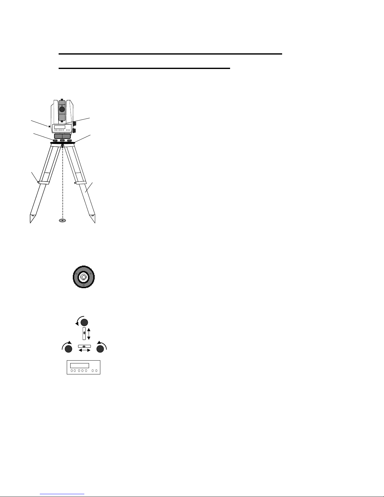
Set-up:
1. Extend the tripod legs (1) to a comfortable height of
observation and fix them using the tripod locking screws 2).
2. Screw the instrument centrally to the tripod head plate (3).
5
6
The tribrach screws (4) should be in mid-position.
4
3
Coarse Centring (when needed):
3. Set up the tripod roughly above the station point
(ground mark), the tripod head plate (3) should be
2
1
approximately horizontal.
4. Centre the circular mark of the optical plummet (5)
above the ground mark using the tribrach screws
or by turning on the Laser dot (turn OFF after use!).
To focus the circle: Turn the eyepiece.
(If using optical plummet , turn the eyepiece to
focus the circle)
To focus the ground mark: Draw out or push in the
eyepiece of the optical plummet. Then push in
or pullout the eyepiece to sharpen the focus.
Coarse Levelling:
5. Level the circular bubble (6) by adjusting the length of
the tripod legs (1).
c)
Precision Levelling:
6. Align the control unit parallel with the imaginary connecting
a)
2
1
line between two tribrach screws. Level the instrument by
b)
turning the tribrach screws a) and b) in opposite directions.
7. Turn the instrument by 90 degrees (100grad) horizontally
and level instrument with tribrach screw c).For checking, turn
the instrument round the vertical axis.
8. After that, check the residual inclination by turning the
instrument in both diametrical positions of (1) and (2). Take
the mean of deviation from center point of level and adjust, if
necessary.
2
Page 3

Precision Centring:
9. Shift the tribrach on the tripod head plate until the image of
the ground mark is in the centre of the circular mark of the
optical plummet; repeat the levelling various times if
necessary.
Telescope Focusing
Focusing the Crosslines:
1. Sight a bright, evenly coloured surface and turn the
telescope eyepiece until the line pattern is sharply defined.
* Attention !
Sighting of the sun or strong light sources must by all
means be avoided. This may cause irreparable
damage to your eyes.
Focusing the target point:
2. Turn the telescope focusing control until the target point is
sharply defined.
3
Page 4
Switching the Instrument ON / OFF
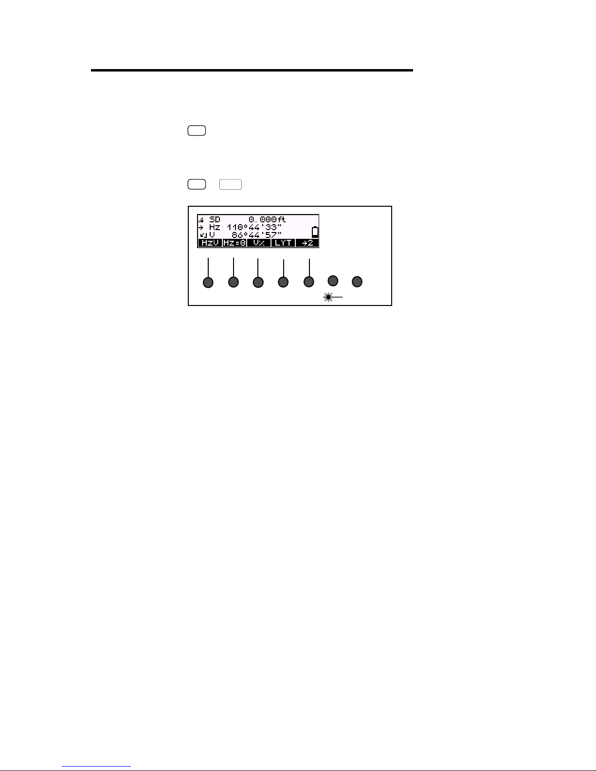
Instrument ON:
ON
Press key ON
Instrument OFF:
ON
OFF
+
OFF DR EDIT PNo MENU SHIFT
Press keys ON plus OFF simultaniously
MEAS ON
4
Page 5
The Display and Keyboard
U
MEAS ON
OFF DR EDIT PNo MENU SHIFT
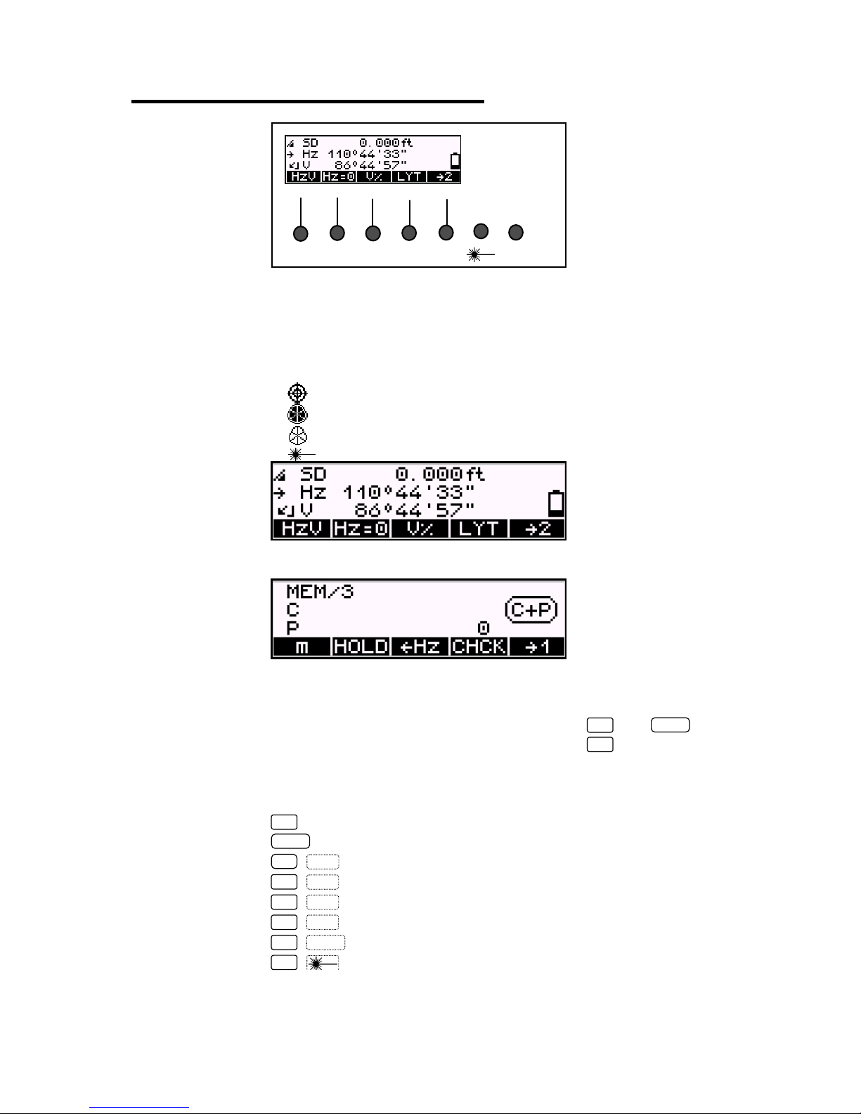
Principle of Display (Measuring screen):
Page 1 Measured / computed values, battery status,
compensator staus
EDM mode, Laser pointer mode,
Display illumination mode
Direct Reflex mode (DR)-„reflectorless“ mode
Direct Reflex mode-“Long Range” mode
Prism mode (PR)-“reflector” mode
Laser Pointer ON
Page 2 Point code, point number, recording
Principle of Keyboard:
Hardkeys Direct functions
Keys in combination with
ON
and
ON
(SHIFT)
Function of Hardkeys
ON
MEAS
ON
OFF
ON
DR
ON
EDIT
ON
PNo
ON
MEN
ON
Switching Laser Pointer ON/OFF
Instrument ON, SHIFT-function
Starting a measurement
Switching the instrument off
Switching EDM Mode PR / DR
Calling up the memory
Calling up the input of point number and code
Going to the main menu
MEAS
Softkey Function depending on program,
5
significance explained in display line at the
bottom
Page 6
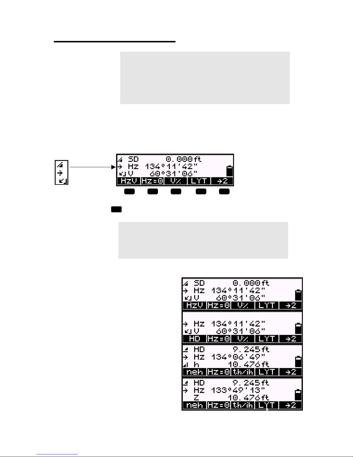
The Measuring screen
* Attention !
In combination with the selection of recording, the
selection of the measuring mode is decisive for:
Which results are to be displayed ?
Which values are to be recorded ?
Selecting the measuring mode
(presentation of the results at the display)
Measuring mode status:
F1
F1
F2 F3 F4
to select the available measuring modes
) Tip
In the display of softkey 1, always the next selectable
measuring mode appears.
SD, Hz, V – display of the original
measured values
Hz, V – display in the theodolite mode
Only for alignments and for setting out
right angles, not for distance
measurement
HD, Hz, h – display of the horizontal
distance and the height difference
F5
Measuring screen page 1
HD, Hz, Z – display of the horizontal
distance and the absolute elevation
6
Page 7

n, e, h – display of the local
coordinates
Measurement in the local system with
station coordinates 0, 0, Zs
n, e, Z – display of the local
coordinates
Measurement in the local system with
station coordinates 0, 0, Zs
) Tip
The measuring modes can be changed at any time
and the results will be displayed immediately in the
selected measuring mode, but not a recording at the
same time. All following measurements are displayed
and recorded in the newly selected mode.
In all measuring modes, the angle reading is updated
continually.
The distance or coordinates are updated only after the
next measurement.
7
Page 8

Before Measurement
U
Frequently used setting:
ON
MEN
+
Ï
to go to the desired menu point
and
Ð
+
to alter the prism constant
and (scale factor, temperature and
-
o.k.
pressure) step by step
to confirm selection / input
Prism constant
Keep / set the prism constant to
–0.018m (-18mm)
Scale factor
Keep the scale factor as
1.000000
Temparature
Set the temperature to the average
seasonal temperature.
Select submenu
1 Input
Air pressure
Set the air pressure to the average
seasonal air pressure.
8
Page 9

Setting of the horizontal angle (Hz circle):
Setting Hz=0
Setting of Hz=0 can be done in the measuring screen
page1 ( softkey
Hz=0
).
Go to page 1 of the measuring screen
F2
to start setting Hz=0; softkey
Sight to the target
YES
to accept setting
and
ESC
to quit
Measuring screen page 1
Setting horizontal angle to zero.
Hz=0
9
Page 10

Setting of the horizontal angle (Hz circle):
Setting Hz to any angle Hz=xxx,xxx
Setting of Hz=0 can be done in the measuring screen
page2 (softkey
HOLD
).
Go to page 2 of the measuring screen
F2
to start setting Hz=xxx,xxx; softkey
HOLD
Turn the instrument to the desired Hz angle (Hz circle value),
read the Hz angle at the display
MEAS
to “freeze” the desired Hz angle
Sight to the target
MEAS
to accept setting
Setting of the horizontal angle count direction:
Setting Hz count direction to clockwise / anticlockwise
Setting of Hz=0 can be done in the measuring screen
page2 (softkeys
Î
Hz
and
Hz
Í
) if you have selected
“SD,Hz,V” or “Hz,V” or “HD, Hz, H” or “HD, Hz, h”.
Go to page 2 of the measuring screen
Î
F3
Hz
to start setting Hz counting direction;
softkeys
Î
Hz
or
Í
Hz
).
press to select Hz counting direction clockwise
or
Hz
Í
press to select Hz counting direction anticlockwise
This setting effects only the reading in the display but not the recording!
10
Page 11

Recording of Point Number and Point Code:
signalises the possibility to enter point
number and code.
ON
PNo
+
+
to browse through the existing character set
Select menu to enter P-number and P-code
and
-
Í
to go to the desired digit of point number and code
and
Î
o.k.
to confirm selection / input
Enter Point-number and Point-code.
The entered values will be recorded
after the following measurement.
C 5-digit point code, alphanumeric notation
P 12-digit point number with the
special characters #, -, . , .numeric notation
) Tip
The toggling between point number and code is realised
continuously.
For fast browsing, keep the respective key depressed.
After the measurement, the point number is
incremented by one unit, the code remains constant
until being modified by the user.
In the application and coordinate programs, the code is
provided with non-varying characters (A,B,..). In this
case, it is not possible to enter the code.
11
Page 12

Setting Target Height (th), Instrument Height (ih)
and
Station Height (Zs):
HD
Z
th
P
h
Z
AP
X/Y
Station
SD
ih
Z
S
The input of the values of target height (th), instrument height (ih) and station
height (Zs – required for height stationing) allows you to measure with absolute
heights (elevations) already in the “Measuring Screen”. If these values have not
been entered, only height differences (h) between the instrument height and the
target height will appear in the display and will be recorded.
If the station height (Zs) is set to “0” the height difference (h) is displayed and
recorded, otherwise the absolute height (ZAP) is displayed and recorded.
These functions appear on the display if you have selected HD/Hz/h, HD/Hz/Z,
n/e/h, n/e/Z or y/x/h, y/x/Z for the displayed values.
th/ih
ESC
Z
th
ih/Zs
o.k.
in measuring modes HD and neh/yxh only
to quit
height stationing
to enter the target height
to enter the instrument and station height
to confirm
Measuring screen page 1 only:
Coordinates ne and height difference h
Horizontal distance HD,
horizontal angle Hz and
height difference h
Target height th, instrument height ih,
station height Zs,
reference height / height stationing Z
12
Page 13

Setting Target height (th) and Instrument height (ih)
1. Measuring height differences h
th
h?
ih
Total Station
Zs=0
The settings of the target- and instrument height can be
done in the following measuring modes only:
HD/Hz/h
HD/Hz/Z
n/e/h
n/e/Z
y/x/h
y/x/Z
F1
F1
F2 F3 F4
to select the measuring modes
F5
F3
F4
F4
13
F1
F2 F3 F4
F5
to select/enter the target height – th
to select/enter the instrument height – ih
to select/enter the station height – Zs
Page 14

To enter the target height (any value)
via input
Via input: Enter target height 6.562 ft
Input of station height (Zs) and
instrument height (ih) via
Internal memory or via input
Current target height is th=0.000ft
Input of station height (Zs) to “0” via
Zs=0
Input of instrument height (ih) via input
Confirm settings
* Attention !
Setting the station height (Zs) to “0”, the height
difference (h) between the station height and the
target height is displayed and recorded.
14
Page 15

Setting Target height (th) and Instrument height (ih)
2. Measuring absolute height Z
ih
Total Station
Zs=xy
AP
th
Z
+h?
h
The settings of the target- and instrument height can be
done in the following measuring modes only:
HD/Hz/h
HD/Hz/Z
n/e/h
n/e/Z
y/x/h
y/x/Z
F1
F3
F4
F4
15
F1
F2 F3 F4
F5
to select the measuring modes
F1
F2 F3 F4
F5
to select/enter the target height – th
to select/enter the instrument height – ih
to select/enter the station height – Zs
Page 16

To enter the target height (any value)
via input
Via input: Enter target height 6.562 ft
Input of station height (Zs) and
instrument height (ih)
Internal memory or via input
Current target height is th=0.000ft
Input of station height (Zs) to “1000” via
Zs=1000.000ft or to any other value via
Input, Zs=1500.000ft
Input of instrument height (ih) via input
Confirm settings
* Attention !
Setting the station height (Zs) to any value except
to “0” the absolute height is displayed and
recorded.
16
Page 17

“Stationing in Elevation”:
ih
th
Z
AP
Total Station
ZS?
The “Stationing in Elevation” can be done in the following
measuring modes only:
HD/Hz/h
HD/Hz/Z
n/e/h
n/e/Z
y/x/h
y/x/Z
Input of th (target height)
and
Zs/ih (reference height / Instrument height)
th 0.000 m to confirm the old target height
input to enter a value (in this case 6.562 ft)
Í
and
Î
+
and
-
o.k.
17
to go to the desired position in the display
to browse through digits
to confirm selection / input
Page 18

To enter the target height (any value)
via input
Via input: Enter target height 6.562 ft
To enter the target height next to last
select th-old
Input of reference height (Zs) and
instrument height (ih) via
Internal memory or via input
Current target height is th=0.000ft
18
Page 19

“Stationing in Elevation”:
Stationing - Measurement
th/ih
Z
Stat
CHCK
ESC
in measuring modes HD and neh/yxh only
Stationing in Elevation
go to the input menus Z, ih, th
Adjusting and checking
to quit the program
→ sight to the backsight point
ON
PNo
+
MEAS
YES
NO
change of the point number?
Measurement
to accept the result, record data, leave the program
to quit, new start
Press th/ih to call the menu for
“Stationing in Elevation”
Press Z to start the
“Stationing in Elevation”
Press Stat to input / call from internal
memory the parameters Z (reference
height), ih (instrument height) and th
(target height), on after the other
Enter reference height
Enter instrument
Enter target height
Aim to the target and press MEAS
Press YES to accept or NO to repeat
the measurement
19
Page 20

Start Measurement
After entering and defining all parameters required you can
carry out the measurement.
MEAS
ON
+
Measuring screen page 1
Measuring screen page2
) Tip
After the measurement, the flush right point number is
incremented by one unit within the number of digits
displayed up to the special character (no figure) to the
left of it.
(According to this picture, counting goes only up to 9,
then it will begin again with "0".)
PNo
press to start measurement
press to enter point number and point code
Display with absolute heights, with
station height Zs, instrument height ih
and target height th entered /
calculated.
Measuring screen page 1
20
 Loading...