

Page 1

TRIMMARK 3 Radio Modem
User Guide
Part Number: 44104-10
Revision: B
Date: March 29, 2002
Trimble Navigation Limited
Surveying & Mapping Division
645 North Mary Avenue
Post Office Box 3642
Sunnyvale, CA 94088-3642
U.S.A.
1-800-827-8000 in North Ame rica
+1-408-481-8000 International
Fax: +1-408-481-7744
www.trimble.com
Page 2

Trimble Navigation Europe Limited
Trimble House, Meridian Office Park
Osborn Way, Hook
Hampshire RG27 9HX
ENGLAND
+44-1256-760-150
Fax: +44-1256-760-148
Voicemail: +44-1256-761-130
Trimble Navigation Singapore PTE Limited
79 Anson Road
# 05-02
Singapore 079906
SINGAPORE
+65-325-5668
Fax: +65-225-9989
Voicemail: +65-325-5668
Trimble Japan K.K.
Sumitomo Hamamatsu-cho, Building 10F
1-18-16 Hamamatsu-cho Minato-ku
Tokyo 105
JAPAN
+81-3-5472-0880
Fax: +81-3-5472-2326
Trimble Navigation New Zealand Limited
11 Birmingham Drive
P.O. Box 8729 Riccarton
Christchurch
NEW ZEALAND
+64-3-339-1400
Fax: +64-3-339-1417
Copyright
© 1998 Trimble Navigation Limited. All rights reserved. No part of this manual may be
copied, photocopied, reproduced, translated, or reduced to any electronic medium or machinereadable form without prior written consent from Trimble Navigation Limited.
Printed in the United States of America. Printed on recycled paper.
Page 3

Revision Notice
This is the second release (Revision B) of the TRIMMARK 3 User Guide, part number 44104-
10.
Tr ademarks
TRIMTALK 450S, TRIMTALK 900, RTK, OSM2, 4000Si, 4000SSi, 4600LS, 4700, 4800,
7400MSi, Sitenet 450, and GPS Total Station are trademarks of Trimble Navigation Limited.
IBM is a registered trademark of International Business Machines, Inc. MS-DOS and
Windows are trademarks of Microsoft Corporation. Intel is a trademark of Intel Corporation.
All other brand names are trademarks of their respective holders.
Notices
Safety. Exposure to RF energy is an important safety consideration. The FCC has adopted a
safety standard for human exposure to radio frequency electromagnetic energy emitted by FCC
regulated equipment as a result of its actions in General Docket 79-144 on March 13, 1986.
Proper use of this radio modem results in exposure below government limits. The following
precautions are recommended:
DO NOT operate the transmitter when someone is within two feet (0.6 meter) of the antenna.
DO NOT operate the transmitter unless all RF connectors are secure and any open connectors
are properly terminated.
DO NOT operate the equipment near electrical blasting caps or in an explosive atmosphere.
All equipment must be properly grounded according to Trimble installation instructions for
safe opera t i on.
All equipment should be serviced only by a qualified technician.
Class A Computing Device—Information to User. This equipment has been tested and
found to comply with the limits for a Class A digital device, pursuant to part 15 of the FCC
Rules. These limits are designed to provide reasonable protection against harmful interference
when the equipment is operated in a commercial environment. This equipment generates, us es,
and can radiate radio frequency energy and, if not installed and used in accordance with the
instruction manual, may cause harmful interference to radio communications. Operation of this
equipment in a residential area is likely to cause harmful interference in which case the user
will be required to correct the interference at his own expense.
Prior to operating these radio modems, users are legally required to obtain frequency
licenses, as required by the country-of-use. Please contact your local communications
governing agency for the licensing requirements for each of these radio modems.
Page 4

Disclaimer of Warranty
E
XCEPT AS INDICATED IN “LIMITED WARRANTY” HEREIN, TRIMBLE HARDWARE, SOFTWARE,
IRMWARE AND DOCUMENTATION IS PROVIDE D “AS IS” AND WITHOUT EXPRESS OR LIMITED
F
WARRANTY OF ANY KIND BY EITHER TRIMBLE NAVIGATION LIMITED OR ANYONE WHO HAS
BEEN INVOLVED IN ITS CREATION, PRODUCTION, OR DISTRIBUTION INCLUDING BUT NOT
LIMITED TO THE IMPLIED WARRANTIES OF MERCHANTABILITY AND FITNESS FOR A PARTICULAR
PURPOSE. THE ENTIRE RISK, AS TO THE QUALITY AND PERFORMANCE OF THE TRIMBLE
ARDWARE, SOFTWARE, FIRMWARE AND DOCUMENTATION, IS WITH YOU. SOME STATES DO
H
NOT ALLOW THE EXCLUSION OF IMPLIED WARRANTIES, SO THE ABOVE EXCLUSION MAY NOT
APPLY TO YOU.
Limitation of Liability
IN NO EVENT WILL TRIMBLE OR ANY PERSON INVOLVED IN THE CREATION, PRODUCTION, OR
DISTRIBUTION OF THE TRIMBLE PRODUCT BE LIABLE TO YOU ON ACCOUNT OF ANY CLAIM FOR
ANY DAMAGES, INCLUDING ANY LOST PROFITS, LOST SAVINGS, OR OTHER SPECIAL,
INCIDENTAL, CONSEQUENTIAL, OR EXEMPLARY DAMAGES, INCLUDING BUT NOT LIMITED TO
ANY DAMAGES ASSESSED AGAINST OR PAID BY YOU TO ANY THIRD PARTY, RISING OUT OF THE
USE, LIABILITY TO USE, QUALITY OR PERFORMANCE OF SUCH TRIMBLE PRODUCT INCLUDING
HARDWARE, SOFTWARE, FIRMWARE AND DOCUMENTATION, EVEN IF TRIMBLE OR ANY SUCH
PERSON OR ENTITY HAS BEEN ADVISED OF THE POSSIBILITY OF DAMAGES, OR FOR ANY CLAIM
BY ANY OTHER PARTY. SOME STATES DO NOT ALLOW THE LIMITATION OR EXCLUSION OF
LIABILITY FOR INCIDENTAL OR CONSEQUENTIAL DAMAGES, SO THE ABOVE LIMITATIONS MAY
NOT APPLY TO YOU.
Software and Firmware Limited Warranty
Trimble Navigation Limited warrants that Software and Firmware products will substantially
conform to the published specifications provided it is used with the Trimble products,
computer products, and operating system for which it was d esigned. For a per iod of ninety (90)
days, commencing thirty (30) days after shipment from Trimble, Trimble also warrants that the
magnetic media on which Software and Firmware are distributed and the documentation are
free from defects in materials and workmanship. During the ninety (90) day warranty period,
Trimble will replace defective media or documentation, or correct substantial program errors at
no charge. If Trimble is unable to replace defective media or documentation, or correct
program errors, Trimble will refund the price paid for The Software. These are your sole
remedies for any breach in warranty.
Page 5

Hardware Limited Warranty
Trimble Navigation Limited products are warranted against defects in material and
workmanship for a period of one year. The warranty period shall commence thirty (30) days
after shipment from Trimble’s factory. Warranty service will be provided at a designated
Trimble Service Center. Trimble will at its option either repair or replace products that prove to
be defective. The Customer shall pay all shipping charges fo r pro ducts returned to Trimble for
warranty service. Trimble shall pay all shipping charges for the return of products to the
Customer.
The above warranty shall not apply to defects resulting from:
1. Improper or inadequate maintenance by the buyer
2. Buyer-supplied software or interfacing
3. Unauthorized modification or misuse
4. Operation outside of the environmental specifications of the product
5. Improper installation, where applicable
6. Lightning or other electrical discharge
7. Fresh or salt water immersion or spray
8. Normal wear and tear on consumable parts (for example, batteries)
No other warranty is expressed or implied. Trimble Navigation Limited specifically disclaims
the implied warranties of fitness for a particular purpose and merchantability.
Page 6

Page 7

Preface
Welcome to the TRIMMARK™ 3 User Guide. This manual describes
the TRIMMARK 3 Radio Modem for use in r eal-time di ffe rential an d
real-time kinematic GPS applications. The radio modem, when used
with a Trimble rover GPS receiver with an internal radio modem,
provides a high- speed wireless dat a link between ba se and rover GPS
receivers.
Scope and Audience
We recommend that you spend some time reading this manual. The
following secti on prov ides y ou with a gui de to t his ma nual, a s well as
to other documentation you have received with this product.
Organization
This manual contains the following chapters and appendices:
• Chapter 1, Overview - provi des a brief overv iew and physical
• Chapter 2, Operation - contai ns configuration and insta llation
TRIMMARK 3 User Guide vii
description of the TRIMMARK 3 radio modem.
instructions for the TRIMMARK 3 radio modem.
Page 8

Preface
• Chapter 3, Characteristics and Specifications - summarizes
performance characteristics and specifications of the
TRIMMARK 3 Radio Modem and Antennas.
• Chapter 4, Troubleshooting - radio status messages and
troubleshooting tips.
• Chapter 5, Regulations and Safety - contains regulation and
safety information.
• Appendix A, Using Radio Communications Systems with
GPS Surveying Receive rs - ge neral informa tion on the use of
with GPS.
Related Information
This manual contains system-wide, general information on the
TRIMMARK 3 radio modem. Other sources of information are
discussed in the following sections.
Update Notes
You will find a Warranty Activation Sheet with your TRIMMARK 3
radio modem. By sending in your Warranty Activat io n Sheet, you are
automatically sent update notes as they become available. When you
receive these packages, read them. They contain important
information about software and hardware changes. Contact your
local Trimble Dealer for more information about support agreement
contracts for softwa re and firmwar e, and extend ed warranty pr ograms
for hardware.
viii TRIMMARK 3 User Guide
Page 9

Other Information
This section lists sources that provide other useful information.
World Wide Web (WWW) Site
For more informati on about Trimble, visit our site on the World W ide
Web:
• www.trimble.com
Preface
TRIMMARK 3 User Guide ix
Page 10

Preface
Technical Assistance
If you have a problem and cann ot find the inform ation you need in the
product documentati on, con ta ct your local Trimble dealer.
Alternatively, request technical support using the Trimble World
Wide Web site:
• www.trimble.com/support/support.htm.
x TRIMMARK 3 User Guide
Page 11

Document Conventions
Italics identify software menus, menu commands, dialog boxes, and
the dialog box fields.
MALL CAPITALS identify DOS commands, director ies, filenames,
S
and filename extensions.
Courier represents messages printed on the screen.
Courier Bold represents information that you must type in a
software screen or window.
Helvetica Bold identifies a software com mand button.
[Ctrl] is an example of a hardware function key that you must press
on a personal computer (PC). If you must press more than one of
these at the same time, t his is repre sented by a plus sign, f or exampl e,
[Ctrl] + [C].
Preface
TRIMMARK 3 User Guide xi
Page 12

Preface
Warnings, Cautions, Notes, and Tips
Warnings, cautions, notes, and tips draw attention to important
information and indicate its nature and purpose.
0
,
)
Warning – W a r nings al ert you to situat ions that could caus e pers on al inju ry
or unrecoverable data l oss.
Caution – Cautions alert you to situations that could cause hardware
damage or software error.
Note – Notes give additional significant information about the subject to
increase your knowledge, or guide your actions.
Tip – Tips indicate a shortcut or other time- or labor-saving hint that can
help you make better use of the product.
xii TRIMM ARK 3 User Guide
Page 13

List of Figures
Figure 1-1 TRIMMARK 3 Front Panel . . . . . . . . . . . . . . 1-6
Figure 1-2 TRIMMARK 3 Rear Panel. . . . . . . . . . . . . . . 1-8
Figure 2-1 WinFLASH Main Window. . . . . . . . . . . . . . . 2-3
Figure 2-2 WinFLASH Operation Selection Window . . . . . . . . . 2-4
Figure 2-3 WinFLASH Configuration Window . . . . . . . . . . . 2-5
Figure 2-4 Standard UHF Omnidirectional Antennas . . . . . . . . . 2-14
Figure 2-5 Directional Antennas . . . . . . . . . . . . . . . . . 2-15
Figure 3-1 Omnidirectional Antenna Gain Patterns. . . . . . . . . . 3-2
Figure 3-2 Directional Antenna Gain Patterns. . . . . . . . . . . . 3-4
TRIMMARK 3 User Guide xiii
Page 14

xiv TRIMMARK 3 User Guide
Page 15

List of Tables
Table 1-1 TRIMMARK 3 Menu Hierarchy . . . . . . . . . . . . 1-7
Table 2-1 Repeater Use in Networks . . . . . . . . . . . . . . . 2-11
Table 3-1 TRIMMARK 3 Physical Specifications. . . . . . . . . . 3-8
Table 3-2 Antenna Physical Specifications . . . . . . . . . . . . 3-9
Table 3-3 Performance Specifications . . . . . . . . . . . . . . 3-10
Table A-1 RF Bands to Avoid When Using GPS Surveying Receivers. . A-3
TRIMMARK 3 User Guide xv
Page 16

xvi TRIMMARK 3 User Guide
Page 17

Table of Contents
Preface
Scope and Audience . . . . . . . . . . . . . . . . . . . . . . . . .vii
Organization . . . . . . . . . . . . . . . . . . . . . . . . . . . . .vii
Related Information . . . . . . . . . . . . . . . . . . . . . . . . .viii
Update Notes . . . . . . . . . . . . . . . . . . . . . . .viii
Other Information . . . . . . . . . . . . . . . . . . . . . . . . . .ix
World Wide Web (WWW) Site . . . . . . . . . . . . . .ix
Technical Assistance . . . . . . . . . . . . . . . . . . . . . . . . .x
Document Conventions. . . . . . . . . . . . . . . . . . . . . . . .xi
Warnings, Cautions, Notes, and Tips. . . . . . . . . . . . . . . . .xii
1 Overview
1.1 Features. . . . . . . . . . . . . . . . . . . . . . . . . . . . . . . .1-1
1.2 Use and Care . . . . . . . . . . . . . . . . . . . . . . . . . . . . .1-2
1.3 Equipment Sets . . . . . . . . . . . . . . . . . . . . . . . . . . . .1-3
TRIMMARK 3 Radio Only Equipment Set. . . . . . . .1-3
TRIMMARK 3 Repeater Equipment Set . . . . . . . . .1-3
TRIMMARK 3 Base Equipment Set . . . . . . . . . . .1-4
1.4 Optional Accessories . . . . . . . . . . . . . . . . . . . . . . . . .1-5
1.5 TRIMMARK 3 Description . . . . . . . . . . . . . . . . . . . . .1-5
1.5.1 Power and I/O Cables . . . . . . . . . . . . . . . . . . .1-9
1.5.2 Defaults . . . . . . . . . . . . . . . . . . . . . . . . . .1-9
1.6 Standard Omnidirectional Antennas . . . . . . . . . . . . . . . . .1-10
TRIMMARK 3 User Guide xvii
Page 18

2 Operation
2.1 Configuration. . . . . . . . . . . . . . . . . . . . . . . . . . . . .2-1
2.1.1 Configuring the Serial I/O Port . . . . . . . . . . . . . .2-1
2.1.2 Getting Started with WinFLASH . . . . . . . . . . . . .2-3
2.1.3 Frequency Updates . . . . . . . . . . . . . . . . . . . .2-7
2.1.4 Firmware Updates . . . . . . . . . . . . . . . . . . . . .2-8
2.2 Installation . . . . . . . . . . . . . . . . . . . . . . . . . . . . . .2-9
2.2.1 TRIMMARK 3 Base/Repeater . . . . . . . . . . . . . .2-9
2.2.2 Antenna Installation . . . . . . . . . . . . . . . . . . . .2-13
Connecting to a Computer. . . . . . . . . . . . . . . . .2-2
Installation as a Base . . . . . . . . . . . . . . . . . . .2-10
Installation as a Repeater . . . . . . . . . . . . . . . . .2-11
Line of Sight Obstruction . . . . . . . . . . . . . . . . .2-13
OmniDirectional Antennas . . . . . . . . . . . . . . . .2-13
Directional Antennas . . . . . . . . . . . . . . . . . . .2-15
3 Characteristics and Specifications
3.1 Antenna Gain . . . . . . . . . . . . . . . . . . . . . . . . . . . . .3-1
3.1.1 Omnidirectional Antennas. . . . . . . . . . . . . . . . .3-1
3.1.2 Directional Antennas . . . . . . . . . . . . . . . . . . .3-4
3.2 Broadcast Network . . . . . . . . . . . . . . . . . . . . . . . . . .3-6
3.2.1 Frequency Band and Channel Selection. . . . . . . . . .3-6
3.2.2 Wireless Data Rate. . . . . . . . . . . . . . . . . . . . .3-7
3.2.3 Transmit Power . . . . . . . . . . . . . . . . . . . . . .3-7
3.3 General Specifications . . . . . . . . . . . . . . . . . . . . . . . .3-8
4 Troubleshooting
4.1 Status Messages . . . . . . . . . . . . . . . . . . . . . . . . . . .4-1
4.2 Service . . . . . . . . . . . . . . . . . . . . . . . . . . . . . . . .4-3
xviii TRIMMARK 3 User Guide
Page 19

5 Regulations and Safety
5.1 Type Approval . . . . . . . . . . . . . . . . . . . . . . . . . . . .5-2
5.2 Licensing . . . . . . . . . . . . . . . . . . . . . . . . . . . . . . .5-2
5.3 Safety . . . . . . . . . . . . . . . . . . . . . . . . . . . . . . . . .5-3
A Using Radio Communication Systems with GPS Surveying
Receivers
A.1 Selecting Communications Radios . . . . . . . . . . . . . . . . . .A-2
A.2 Useful Field Procedures . . . . . . . . . . . . . . . . . . . . . . .A-5
A.3 Summary . . . . . . . . . . . . . . . . . . . . . . . . . . . . . . .A-6
Index
TRIMMARK 3 User Guide xix
Page 20

xx TRIMMARK 3 User Guide
Page 21

1 Overview
The rugged TRIMMARK 3 radio modem is designed to operate in
harsh environments , such as thos e associate d with seismi c and mining
surveys. Used with a Trimble rover GPS receiver with an internal
radio modem the TRIMMARK 3 provides a convenient, versatile
means of establishing a robust wireless data broadcast network for
real-time differential and real-time kinematic GPS applications.
1.1 Features
The TRIMMARK 3 has the following standard features:
• 20 channel capability
• Selectable 2, 10 and 25 Watts Transmit Power
• Narrowband UHF technology, available in three UHF bands:
(410-420 Mhz, 430-450 Mhz, 450-470 Mhz)
• Wireless data rate of 4800, 9600 or 19200 bps
• Interfaces with all Trimble survey-grade GPS receivers
• Channel Sharing (carrier detect)
• Supports up to two repeaters in a single network
• Rugged, weatherproof constr uct ion
• Two line, 16-character VFD display
• Trimble CMR and RTCM SC-104 Version 2.x compatible
TRIMMARK 3 User Guide 1-1
Page 22

Overview
1
• Operational parameters configured through WinFLASH
utility, handheld controller or front panel.
• Configured as Base, Repeater or Rover
• Compatible with TRIMTALK 450S, TRIMMARK II & IIe,
SiteNet 450 external radios and 4700 , 4800 and 5700 inte rnal
radios
Note – As used in this manual, CMR as well as CMR Plus formats are both
represented by CMR.
1.2 Use and Care
The TRIMMARK 3 as a base or repeater is programmable in 2, 10
and 25 Watt output modes. As a rover the unit will receive only.
When the unit is configured as a base or rover it can be connected to
most Trimble survey-grade GPS receivers through a single cable for
serial I/O and a separat e cable for power. When used as a repeater the
TRIMMARK 3 unit operates autonomously and requires only a
power and antenna connection, with no connection to the serial port.
T o ac hieve lin e-of- sight (LOS) cove rage to all poin ts in a sur vey area,
a TRIMMARK 3 radio modem network can include up to two
repeaters, depending on data format and output data rate. The
repeaters retransmit data packets according to a simple time-sharing
scheme to avoid mutual interference, and their operation is
transparent to the rover s. The rover s will use th e data pack et fr om the
base or repeater, whichever the rover detects first.
The TRIMMARK 3 unit is designed to withstand rough treatment
typical of equipment used in the fiel d. However , the unit i s a precision
electronic inst rument and should be t reate d with rea sonable care. The
radio modem operates in temperatures ranging from -40°C to +65°C
(–40°F to 149°F). The enclosure is sealed and weatherproof.
1-2 TRIMMARK 3 User Guide
Page 23

1 Overview
Warning – Opera ting or storing your TR IMMARK 3 radio modem outside
0
the specified temperature range can damage the instrument.
1.3 Equipment Sets
The TRIMMARK 3 is available as a stand-alone produ ct or in one of
two standard equipment sets, base or repeater. These standard
equipment sets are designed fo r use with GPS receivers such as the
Trimble 4700, 4800 and 5700. The equipment sets contains the
accessories required to operate the radio modems including cables,
mounts, and antennas.
TRIMMARK 3 Radio only (P/N 44100-10-xx)
The TRIMMARK 3 Radio only configuration consists of the
following components:
• TRIMMARK 3 Radio Modem (P/N 46000-xx)
• Power Cable (P/N 40356)
• Programming Cable (P/N 32960)
• TRIMMARK 3 CD, (P/N 47085-00)
TRIMMARK 3 Repeater Equipment Set (P/N 44100-20-xx)
The standard TRIMMARK 3 Repeater Equipment Set consists of the
following components:
• TRIMMARK 3 Radio Modem (P/N 46000-xx)
• TRIMMARK 3 Transport Case (P/N 44072-00)
• Power Cable (P/N 40356)
1
1
1
1
• Programming Cable (P/N 32960)
• TRIMMARK 3 CD (P/N 47085-00)
TRIMMARK 3 User Guide 1-3
Page 24

Overview
1
• Mounting Pole (P/N 44091-00)
• Antenna Mounting Pole Plate (P/N 44092)
• Antenna & Pole Carry Pouch (P/N 44098-00)
• Whip Antenna Kit, 0dB/5dB (P/N 44075-xx)
(includes antenna mount and cable, P/N 22720-10)
TRIMMARK 3 Base Equipment Set (44100-30-xx)
1
The standard TRIMMARK 3 Base Equipment Set consists of the
following components:
• TRIMMARK 3 Radio Modem (P/N 46000-xx)
1
• TRIMMARK 3 Transport Case (P/N 44072-00)
• Power Cable (P/N 40356)
• Programming Cable (P/N 32960)
• TRIMMARK 3 CD (P/N 47085-00)
• Antenna Mounting Pole (P/N 44091-00)
• Antenna Mounting Pole Plate (P/N 44092)
• Antenna & Pole Carry Pouch (P/N 44098-00)
• Whip Antenna Kit, 0dB/5dB (P/N 44075-xx)
(includes antenna mount and cable, P/N 22720-10)
• 8 meter (25 foot) Data I/O Cable, (P/N 31288-08)
1-4 TRIMMARK 3 User Guide
1
xx = 42, Frequency Band is 410-420 Mhz
1
xx = 44, Frequency Band is 430-450 Mhz
1
xx = 46, Frequency Band is 450-470 Mhz
Page 25

1 Overview
Note – The standard base and repeater equipment sets are designed for use
with GPS receivers such as the Trimble 4700, 4800 and 5700. Contact your
local Trimble representative for information about connecting to other GPS
receivers.
1.4 Optional Accessories
The following accessories may be purchased in addition to the
standard system.
• 18AH Battery with Carry Pouch (P/N 44103-18)
• Battery Charger, 18AH (P/N 44111-00)
1.5 TRIMMARK 3 Description
The TRIMMARK 3 radio modem is packaged in a weatherproof
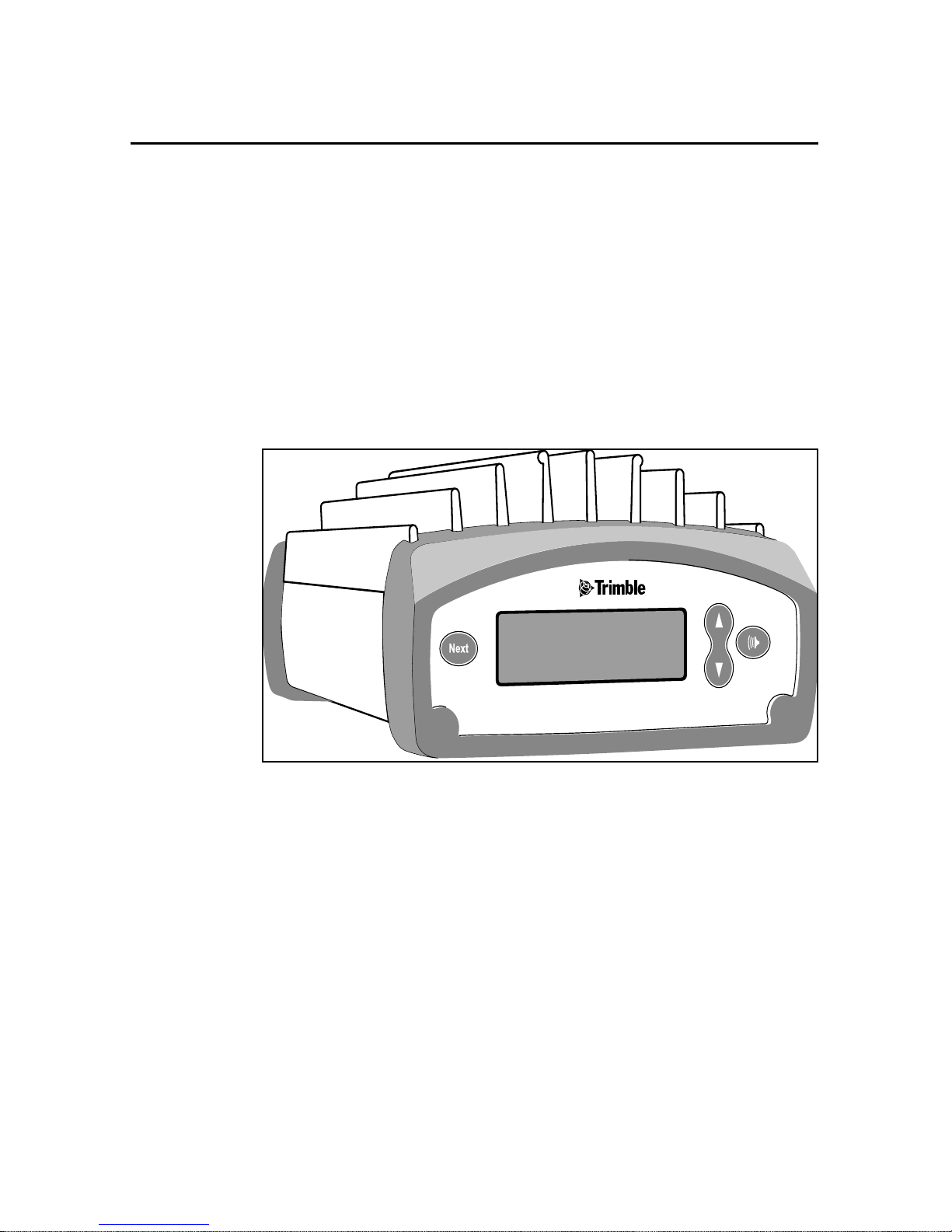
housing. The front panel, see Figure 1-1, has a VFD display to
indicate channel f requency, radio status and error messages. Ther e are
seven main menus available through the front panel:
• CHANNEL: Channel number and operating frequency
• MODE: Base, Repeater or Rover modes
• CHANNEL SHARING: Carrier Detect settings
• TRANSMIT POWER: 2,10 or 25 Watts
• WIRELESS MODE: Over-the-air data rate settings
• DATA PORT CONFIG: Data port baud rate settings
• DEVICE STATUS: Radio programming information
TRIMMARK 3 User Guide 1-5
Page 26
Overview
1
The default menu on power-up is the CHANNEL menu, with the
additional menus s el ectable through the f ront panel control keys. The
front panel keys are as follows:
• SPEAKER
• UP
• DOWN
• NEXT
Figure 1-1 TRIMMARK 3 Front Panel
The SPEAKER button on right side the radio front panel controls the
volume of the re ceived aud io signal on the cur rently s elected channel.
If traffic is present, you will hear the traffic if the volume is adjusted
high enough.
1-6 TRIMMARK 3 User Guide
Page 27

1 Overview
The UP and DOWN buttons scroll through the various items within
the individual menus.
The NEXT button is used to br owse tho ugh the var ious menu screen s.
Table 1-1 details the main menu items and the various selections
within the main menus. Certain items displayed on the front panel
will differ according to your units settings.
Main Menu
Channel
Mode
Channel Sharing
Transmit Power
Wireless Mode
Data Port Config
Devices Status
Menu Selection
1 461.025
Base w/ No Rpt Base w/ One Rpt Base w/ Two Rpt Repeater 1 Repeater 2 Rover
Off
Low Power 2 W Med Power 10 W High Power 25 W
TM II 4800 bps TT450S 9600 bps TT450S 4800 bps TM3 19200
38400 8-none-1 38400 8-odd-1 9600 8-none-1 9600 8-odd-1
Call Sign
(On/Off)
2 461.075
Avoid Weak Sig Avoid Strong Sig
CS: (call sign) Ser: (unit serial #) Ch Spacing
3 461.100
4 462.125 5 462.375 (up to 20
bps
(12.5/25 kHz)
channels)
Table 1-1 TRIMMARK 3 Menu Hierarchy
Note – Certain standar d featur es may be disab led in you unit to comply with
your country-of -use regulations.
TRIMMARK 3 User Guide 1-7
Page 28
Overview
1
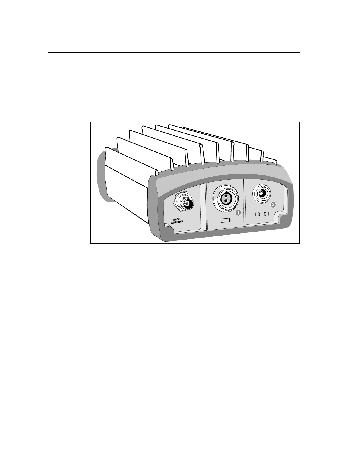
The rear panel, see Figure 1-3, has three electrical connectors:
• POWER connector (two-pin LEMO)
• DATA connector (seven-pin LEMO, 0-shell)
• ANTENNA connector (female TNC)
•
Figure 1-2 TRIMMARK 3 Rear Panel
1-8 TRIMMARK 3 User Guide
Page 29

1 Overview
1.5.1 Power and I/O Cables
The TRIMMARK 3 base equipment set comes with a radio to
receiver I/O cable (not provided in the repeater equipment set), an
antenna cable with integrated antenna mount, a power cable and a
configuration cable (PC to radio modem). The configuration cable
allows you to modify the radio modem configuration using the
Trimble WinFLASH utility. See figure 1-4 for the cable connection
diagram.
When configured as a base, the radio modem receives data at the
DATA connector through a single LEMO-to-LEMO cable that plugs
into a Trimble GPS receiver. When the unit is configur ed as a
repeater, the data connection is not required.
Power is connected to the unit at the POWER connector from a
suitable power source, either a stable DC power supply or a battery.
1.5.2 Defaults
The TRIMMARK 3 radio modem is shipped from the factory with
the following default settings.
• CHANNEL: Channel 1
• MODE: Base with No Repeater
• CHANNEL SHARING: Off
• TRANSMIT POWER: Low Power 2 Watts
• WIRELESS MODE: TMII 4800 bps
• DATA PORT CONFIG: 38400 8-None-1
• DEVICE STATUS: Call Sign Off
Note – Prior to use of your TRIMMARK 3, you should change the radio
settings to meet your specific requirements using the WinFLASH utility
provided on the TRIMMARK 3 CD.
installation and configuration information.
Please refer to Chapter 2 for
TRIMMARK 3 User Guide 1-9
Page 30

Overview
1.6 Standard Omnidirectional Antennas
Each radio modem, when purchased as part of a base or repeater
equipment set, is supplied with a standard omnidirectional antenna.
The omnidirectional antenna provided is a 5dB gain UHF antenna
with an interchangeable 0dB tip.This antenna can be used with a unit
configured as a base or repeater. The antenna threads onto an
integrated antenna mount and cable. The integrated antenna mount
attaches to the anten na mounti ng pole on top of a tripod us ing a tripod
mounting plate.
1
1-10 TRIMMARK 3 User Guide
Page 31

2 Operation
The TRIMMARK 3 radio modem contains both a data modem and a
radio. It can be used in a variety of c onf igurations to form a compl et e
wireless data network. A typical configuration is as a base radio
modem broadcasting directly to a Trimble 4700, 4800 or 5700 Rover
GPS receiver that co ntains an in ternal radio modem. Alternatively,
the TRIMMARK 3 may also operate as a repeater.
2.1 Configuration
Each TRIMMARK 3 radio modem comes from the factory
programmed with default settings as defined in Chapter one of this
manual. The factory default parameters are stored in nonvolatile
memory and serve as the initial power-up settings for the radio
modems. The unit retrieves the p arameters stored in non-volatile
memory at each power-up. The power -up setting s can be reconfigured
as often as necessary using the WinFLASH Utility. Certain
parameters may also be changed using the front panel menus
2.1.1 Configuring the Serial I/O Port
TRIMMARK 3 User Guide 2-1
Note – The BAUD RATE, FORMAT, and CTS parameters for the GPS
receiver must be configured to properly transfer data between the receiver
and the radio modem. BAUD RATE must be set to match the maximum
serial I/O rate of the radio modem (38400 bps) and is always set to 8-NONE-
1. CTS flow control is disabled.
Page 32

Operation
2
The radio modem must be connected to a computer running
Microsoft Windows 95/98 or Windows NT to run the WinFLASH
utility. Perform the following procedures to connect the unit to your
computer, install the WinFLASH Utility under Windows, and set up
the serial I/O parameters. Alternatively, the serial port communication
parameters may be configured from the front panel in the Data Port
Config menu.
Note – Your computer must be able to support a 38400 bps serial port data
rate.
Connecting to a Computer
Connect the radio modem programming cable (P/N 32960) to the
serial COM port on the computer and the I/O port on the radio.
Connect power cable (P/N 40356) to the POWER connector from a
suitable power source.
2-2 TRIMMARK 3 User Guide
Page 33
2 Operation
2.1.2 Getting Started with WinFLASH
WinFLASH is a communications setup utility used to configure the
TRIMMARK 3. You need Microsoft Windows 95/98/2000 or
Windows NT to run WinFLASH on your computer. Read the
README.TXT file provided on the WinFLASH diskette or use the
Microsoft W indows documentat ion for information on the installation
of Wi nFLASH and an icon on your desktop.
Using WinFLASH
To use WinFLASH, do the following:
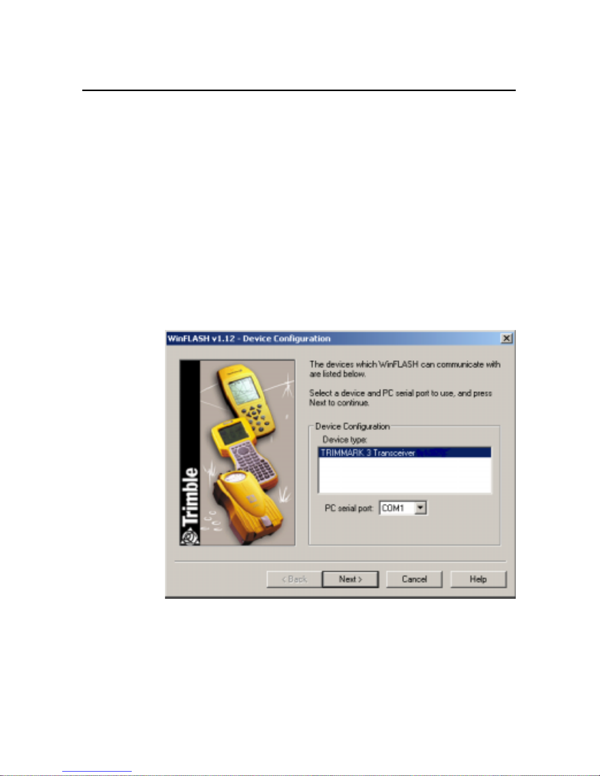
1. Select and open the WinFLASH icon to start WinFLASH. The
WinFLASH main window will be displayed as shown in
Figure 2-1.
Figure 2-1 WinFLASH Main Window
TRIMMARK 3 User Guide 2-3
Page 34
Operation
2
2. Follow the directions in the WinFLASH window to make a
logical connection to the radio modem.
a. Se lect the appropriate PC serial port (COM port).
b. Select the appropriate device, TRIMMARK 3
Transceiver and Press [Next}.
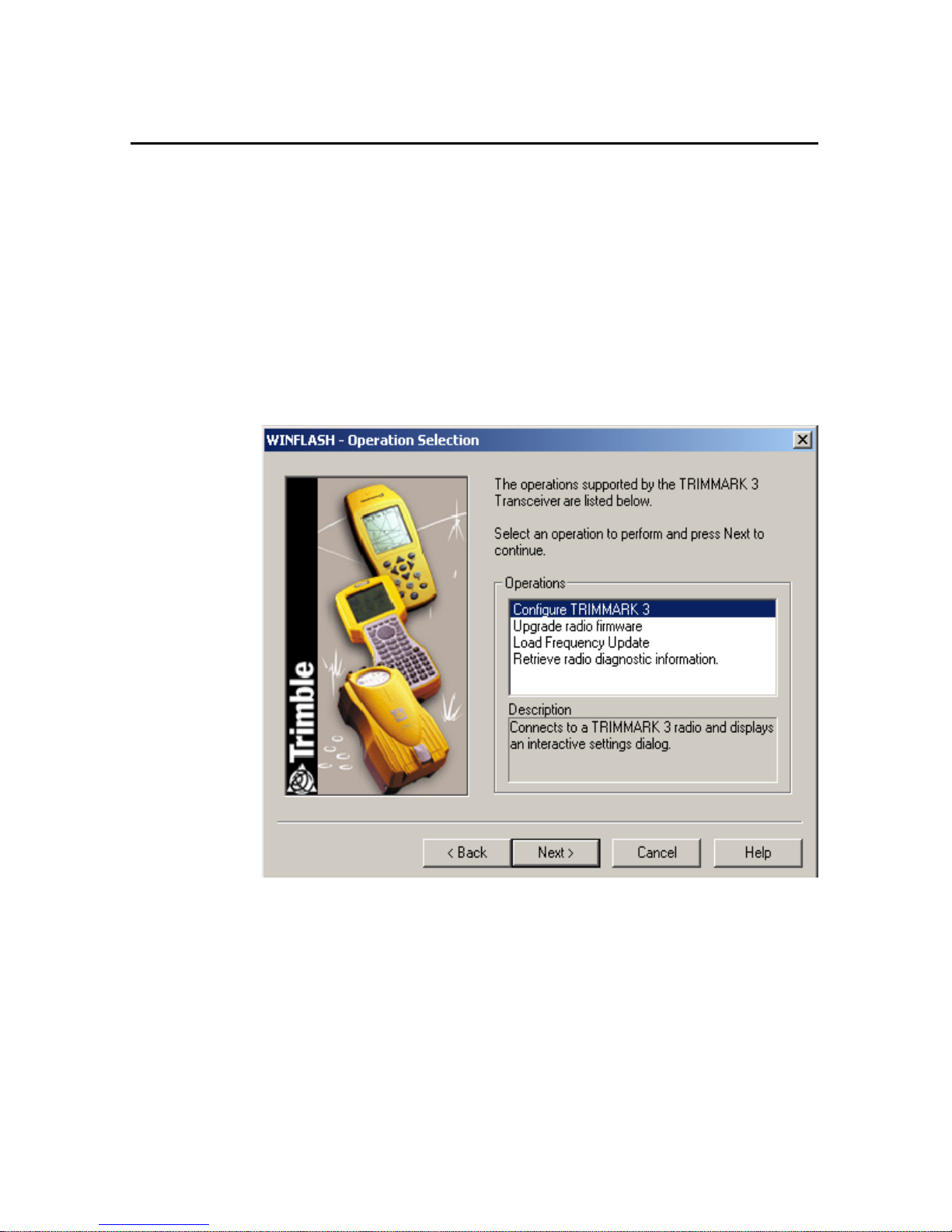
The Operation Selection Window as shown in Figure 2-2
appears.
Figure 2-2 Operation Selection Window
3. Select the appropriate operation in the Operations window,
2-4 TRIMMARK 3 User Guide
Configure TRIMMARK 3, and Press [Next].
a. The Settings Review window appears to confirm you
selected operation, Press [Finish].
Page 35
2 Operation
b. A connection status window appears, counts to 100%,
and then displays the TRIMMARK 3 configuration
menu.
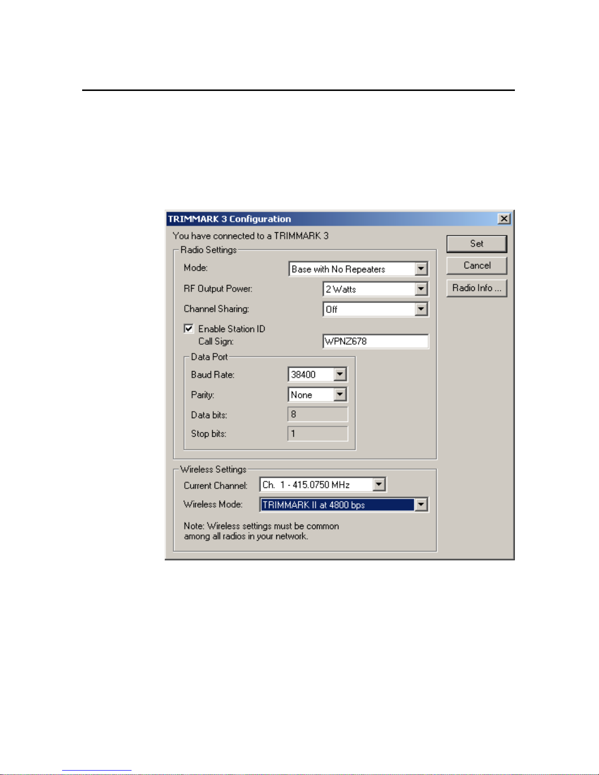
When a successful connection is established, the TRIMMARK 3
Configuration window (Figure 2-3) replaces the WinFLASH window.
Figure 2-3 Configuration Window
Use the dialogs in the TRIMMARK 3 Configuration window to
modify configuration parameters.
TRIMMARK 3 User Guide 2-5
Page 36

Operation
2
Perform the following ste ps to conf ig ure the TRIMMARK 3:
1. Select the ap propriate o perating Mode depending on i ntended
use, for example; Base with No Repeaters.
2. Select the appropri ate RF Output Power. 2, 10 or 25 Watts.
3. Select the Channel Sharing configuration: (Base modes
only, not selectable for a Repeater or Rover)
Off: The c arrier detect mode is OFF and your uni t will i gnore
other transmissions on your frequency and continue to
transmit data.
Note – Channel Sharing set to Off may be illegal in your country-of-use. Y ou
may be subject to penalties or fines dependant upon the specific licensing
requirements for your country-of-use. Please consult your radio license
documentation or licensing agency for operational guidelines.
Avoid Weak Signals: The carrier detect mode is ON and the
radio will cease transmitting if it detects another radio
transmission on it’s frequency. It will resume transmission
when the channel is free of radio traffic.
Avoid Strong Signals: The carrier detect mode is ON, but the
radio will only st op tran smitting when ther e is a stron g signa l
present. (Receive level >-90 dB)
4. Check the Enable Station ID box and input your Call Sign
into the box. This is a Federal Communications Commission
requirement for U.S. licensed users. This sets your radio to
transmit your Call Sign every 15 minutes in Morse Code.
5. In the Data Port dialog set the Baud Rate and Parity. This is
the communications settings between the receiver and radio.
2-6 TRIMMARK 3 User Guide
Note – The factory defaul t GPS Po rt p aramet ers fo r the TR IM MARK 3 are
38400 Baud Rate with None Parity. The factory default Mode is Base with
no Repeater with Channel Sharing set to OFF.
Page 37

2 Operation
6. In the Wireles s Settings dialog, sel ect the appropriate
Current Channel, which determines the radio operating
frequency. Next, select the desired Wireless Mode, which
determines the over-the-air communicatio ns set ti ngs .
)
Note – All Radios in the network must be configured w ith the same W irel ess
Mode Setting, or the radios will not communicate.
7. To update the configuration click on the [Set] button. You
will then see a Status dialog box. You may now return to the
main menu, or exit WinFLASH.
8. The [Radio Info] button allows the user to view a text listing
of all the radio information, including it’s current
configuration.
Tip – You ma y print or save to fil e the radio configura tion info rmation fo r
future reference. The saved fi l e can be p rint ed an d s ent via fax or emailed to
Trimble Support to aid in troubleshooting radio problems.
2.1.3 Frequency List Updates
The TRIMMARK 3 radio modem can be programmed with a list of
up to 20 frequencies, stored in non-volatile memory. This list is
preconfigured based on the frequencies requested when the unit was
ordered. Governme ntal reg ulations require that onl y manufactur ers or
authorized dealers can create this frequency list. All frequencies
programmed into a TRIMMARK 3 radio modem must comply with
the host country regulations.
When you need to change the frequency list (add, delete, or replace
frequencies), contact your Trimble dealer and provide the
TRIMMARK 3 radio modem’s serial number and an updated list of
the frequencies you require. Once you have been provided the
frequency file y ou may upgr ade th e radi o using the WinFLASH utility.
TRIMMARK 3 User Guide 2-7
Page 38

Operation
2.1.4 Firmware Updates
TRIMMARK 3 firmware upgrades will periodically be available at
the Trimble World Wide Web (www.trimble.com). The radio
firmware may also be upgrad ed usi ng the WinFLASH utility program.
2
2-8 TRIMMARK 3 User Guide
Page 39

2 Operation
2.2 Installation
Before setting up the equipment in the field, verify that each radio
modem is set to the same channel and wireless data rate. Also verify
that the radio modem’s Data Port settings are 38400 Baud Rate and
None Parity by using the WinFLASH utility or front panel. Set the
serial port settings for both base and rover GPS receivers to 38400
bps, 8 bits, none parity and 1 stop bit. Refer to the GPS receiver
manual for general GPS receiver setup information.
Note – High-power sig nals fro m a near-by high-power radio station or rada r
transmitter can overwhelm the radio modem circuits. This does not harm the
instruments, but can prevent them from functioning correctly. To avoid
problems, try not to use the radio modems within 400 meters (1300 feet) of
powerful radar, television, or other transmitters. Low-power transmitters
such as the ones in portable phones and walkie-talkies normally do not
interfere with TRIMMARK 3 radio modem oper atio ns unless th ey are tuned
to the same channel as your radio modem units. Always monitor any
frequency before and during operation. Only transmit on a clear channel.
Also, to avoid possible interference with GPS reception, keep the
base radio modem an tenna as far as possi ble from the GPS ant enna. A
minimum of 3 meters (10 feet) is recommended.
Refer to Using Radio Communication Systems with GPS Surveying
Receivers, page A-1, which is a copy of Trimble publication 1-6120082-2/94 Using Radi o Communication systems with GPS Surveying
Receivers, for precautions in using certain frequencies that can
interfere with GPS operation.
2.2.1 TRIMMARK 3 Base or Repeater
The TRIMMARK 3 radio modem can be installed in a network as a
base station or as a repeater. Typically the base is configured for 25
Watts output, and the repeater is configured at 2 Watts output power.
TRIMMARK 3 User Guide 2-9
Page 40

Operation
2
Installation as a Base
To use a TRIMMARK 3 radio modem as a base, do the following:
1. If necessary, reconfigure th e unit’s serial port settin gs to those
of the GPS receiver. Configure the unit as appropriate, base
with no repeaters, or with one or more repeaters. Ensure that
all units in your network are configured according to their
specific task within the network.
2. Before connecting the power cable, thread the base antenna
onto the mounting pole.
3. Mount the entire antenna assembly on a tripod using the
tripod mounting plate and connect the antenna cable to the
TRIMMARK 3 radio modem.
4. Attach the antenna cable to the ANTENNA port on the unit.
5. Connect the power cable between the TRIMMARK 3
POWER port and an appropriate 12V DC power source.
,
Caution – Be careful to connect the power cable with the correct polarity.
Reversing polarity does not damage the base radio modem, however the
protective 10 Amp fuse in the power cable will blow.
6. Connect the 8 meter (25-foot) data cable between the base
radio modem DATA port and the GPS receiver data port. For
the Trimble 4700,4800 or 5700 GPS receivers, this is Port 3
7. If the GPS receiver is outpu tting dat a, the bas e should now b e
in operation. Check the display on the TRIMMARK 3 and
verify that the "TRAN" (transmitting) message is flashing.
8. If the TRIMMARK 3 displays "BUSY", another radio
transmission is present on the frequency you selected.
Change frequencies until you locate a clear channel.
9. Verify that you are on the correct channel, and power output.
2-10 TRIMMARK 3 User Guide
Page 41

2 Operation
Installation as a Repeater
To achieve coverage to all points in a survey area, a TRIMMARK 3
network may include up to two repeaters.The repeaters retransmit
data packets in a way that avoids mutual interference w ith the bas e
and each other. The operation of the repeaters is transparent to the
rovers. The rover will use the data packets from the base or repeater,
whichever it receives first.
The option to inc lude a re peater i n a TRIMMARK 3 net work depends
on the selected wireless data rate and the broadcast information
content and rate (tha t i s, CMR vs . RTCM 2.x RTK packets at 1Hz vs.
5Hz RTK epoch rates). Table 2-1 illustrates when a repeater may be
used in a network for various wireless data rates, RTK formats and
RTK epoch rates.
Table 2-1 Repeater Use in Networks
Wireless
Data Rate
(bps) DGPS
CMR
at 1 Hz
CMR
at 5 Hz
RTCM 2.x at
1 Hz
48001100
96002211
19200 2 2 1 2
"2" - Two repeaters may be used
“1” - One repeater may be used
“0” - No repeaters may be used
To install a TRIMMARK 3 radio modem as a repeater, do the
following:
1. Verify that t he TRIMMARK 3 i s conf igure d for Rep eater 1 if
you are using only one repeater. If you are using a second
repeater verify it is also configured properly as Repeater 2.
2. Verify that the Base is set to be used as Ba se w/ One Repeater
or Base w/ Two Repeaters as appropriate.
TRIMMARK 3 User Guide 2-11
Page 42

Operation
2
3. Before connecting the power cable, assemble the repeater
antenna, attach it to its mount, and then thread the complete
assembly onto the antenna mounting pole.
4. Mount the entire ant enna assembl y and pole on a tripod usi ng
the tripod mounting plate, and connect the antenna cable to
the TRIMMARK 3 radio modem at the Radio Antenna port.
5. Connect the power cable between the TRIMMARK 3
POWER port and an appropriate 12V DC power source. The
front panel should dis play th e Channel menu with t he cur rent
channel being used.
,
Caution – Be careful to connect the power cable with the correct polarity.
Reversing polarity does not damage the base radio modem, however the
protective 10 Amp fuse in the power cable will blow.
6. Select the repeater radio modem channel to match the base
radio modem channel by pressing th e UP or DOWN key until
the appropriate channel setting is displayed.
7. Press the NEXT key until TRANSMIT POWER is disp la yed
and select the appropriate power setting: 2,10 or 25 Watts.
Note – Using the minimal power setting to meet your needs will, conserve
battery power, and minimize the chance of your radio system interfering
with other users.
8. Verify that the cha nnel ass ignments are the same for all bas e,
rover and repeater units.
9. The repeater should now be in operation. When data
broadcast by the ba se is rece ive d by t he rep eater, the unit will
flash Rpt (repeat) in the upper right corner of the display.
2-12 TRIMMARK 3 User Guide
Page 43

2 Operation
2.2.2 Antenna Installation
Several factors should be considered when installing and locating
antennas. Place a ntennas as high as leg ally po ssibl e above th e gro und
and surrounding obstructions such as trees, vehicles, buildings, and
hills.
Note – Antenna height is the most important factor in achieving maximum
range with radio modems. Doubling the antenna height results in a 40%
increase in line-of-sight range. Use low loss cable if it is necessary to
increase the length of the antenna cable to accommodate your installation.
Consult your license for the legal limits on antenna height.
Line of Sight Obstruction
Objects placed near the antennas, especially metal objects, can
severely limit their efficiency. If an antenna is to be mounted on an
antenna mast, make sure the antenna is mounted so that its radiating
element is completely above the top of any obstructing source if
possible.
Omnidirectional Antennas
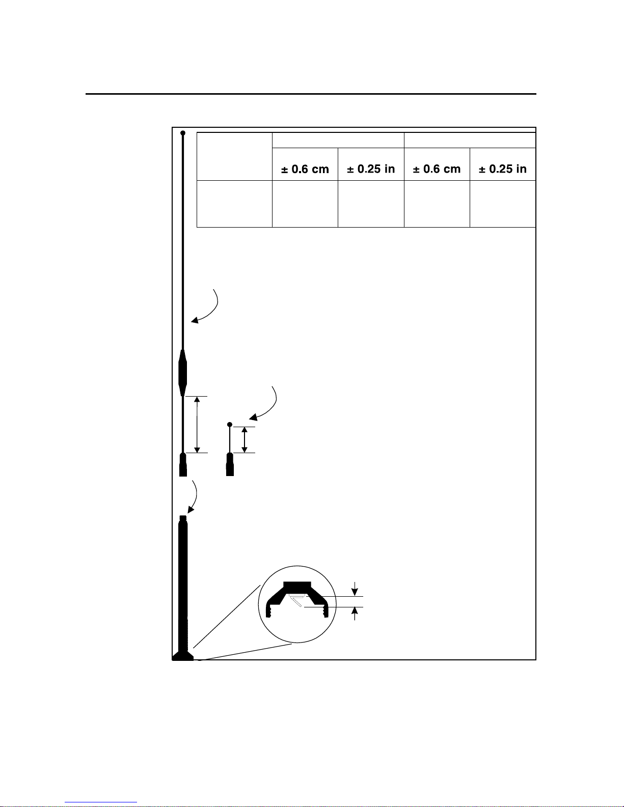
The UHF Whip antenna shipped with your system is factory tuned to
operated in the band (Example: 450-470 Mhz) you specified with
your order. Refer to figure 2-4 to ensure that your antenna is the
correct length for your frequency band.
TRIMMARK 3 User Guide 2-13
Page 44
Operation
2
.
Frequency
Band
(cm)
L1
(in) (cm) (in)
L2
(MHZ)
406-430 20.3 8 15.0 5.9
430-450 17.4 6.8 12.3 4.8
450-470 16.9 6.6 13.3 5.2
IMPORTANT
Check these lengths and
adjust if necessary by
5 dB gain tip
0 dB gain tip
L1
loosening Allen screw
L2
Hand tighten desired antenna
tip onto antenna feed.
IMPORTANT
Check that the contact tab in
the base of the antenna feed
is at a 45 angle.
0.5 to 0.6 cm
(0.2 to 0.25 in.)
Figure 2-4 Standard UHF Omnidirectional Antennas
2-14 TRIMMARK 3 User Guide
Page 45
2 Operation
Directiona l Antennas
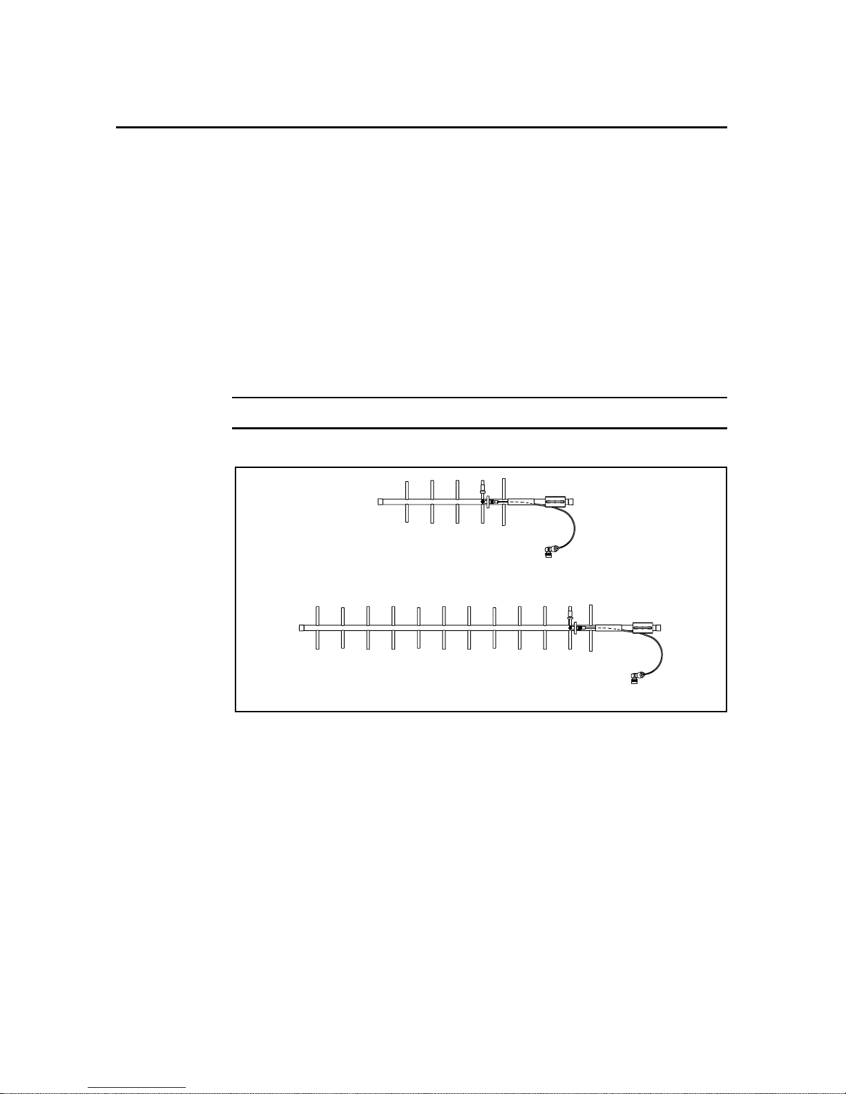
As an option, directional antennas can increase the range in a
particular direction, see Figure 2-5. The directional antenna must be
pointed in the direction of the receiving or transmitting antenna to
take full adva ntage of its a ntenna d esign. The se anten nas are designed
to be mast mounte d with the ant enn a ele ments ve rtic ally orient ed. All
directional an te nnas i n a wi reles s dat a network must be mou nte d with
their antenna el ements aligned in t he same ori entation. For additi onal
information re fer to th e applicati on sheet suppli ed with the dir ectional
antenna.
Note – Government regulations may exclu de t he use of direct ion al antennas .
9 dB Yagi antenna
12 dB Yagi antenna
Figure 2-5 Directional Anten n as
TRIMMARK 3 User Guide 2-15
Page 46

Operation
2
2-16 TRIMMARK 3 User Guide
Page 47

3 Characteristics and
Specifications
This chapter briefly summarizes general characteristics and
specifications of the TRIMMARK 3 radio modem.
3.1 Antenna Gain
The antennas supplied with the TRIMMARK 3 do not increase the
energy radiated by the radio modem. They concentrate the energy
from the radio modem in a particular direction. The degree to which
they concentrate radio frequency energy in any particular direction is
called directivity and is measured in dB, or decibels. The greater the
antenna gain in dB, the higher the directivity and the more the
radiated energy from the antenna is concentrated in some direction.
3.1.1 Omnidirectional Antennas
An antenna that radiates energy equally in all directions in the
horizontal plane is called omnidirectional. Omnidirectional antennas
radiate an equal amount of energy at every azimuth. However, they
are not omnidirectional in the vertical plane.
TRIMMARK 3 User Guide 3-1
Page 48
Characteristics and Specifications
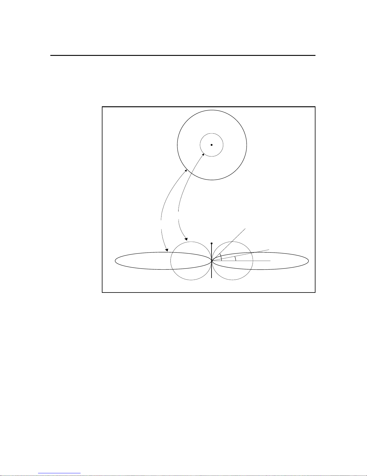
Figure 3-1 shows the radiated energy patterns of the UHF
omnidirectional antennas used with the radio modems. All
omnidirectional antennas must be oriented vertically when used.
top view
3
Azimuth
0 dB
5 dB
ground level
view
Elevation
45˚
12˚
Figure 3-1 Omnidirectional Antenna Gain Patter ns
The top view shows radiated energy patterns in the horizontal, or
azimuth plane of the antennas, the plane that perpendicularly bisects
the length of the antenna. For omnidirectional antennas, all azimuths
receive equal energy, but the 5 dB antenna radiates almost four times
more power in the horizontal plane than does the 0 dB antenna. In an
open field, four times more power approximately doubles the range.
3-2 TRIMMARK 3 User Guide
Page 49

3 Characteristics and Specifications
The ground level view shows radiated energy patterns in the vertical,
or elevation, pla ne of th e anten nas . Much of th e en er gy fr om the 5 dB
antenna is concentrated in elevation to within ±12° of horizontal. A
rover antenna wit hin this sector r ec eives stronger si gnal s from a 5 dB
antenna. However, at angles greater than 12° from horizontal, the 0
dB gain antenna radiates more energy.
Antenna gain has exactly the same effect on signal reception as it
does on signal transmission. A high gain rover antenna can increase
range performance as long as it is oriented correctly with respect to
the transmit antenna. For high g ain antennas, this means keeping the
antenna element ver tica l and at the same elevat ion as the transmit ting
antenna. Otherwise, it may be better to use an antenna with less gain.
TRIMMARK 3 User Guide 3-3
Page 50
Characteristics and Specifications
3.1.2 Directional Antennas
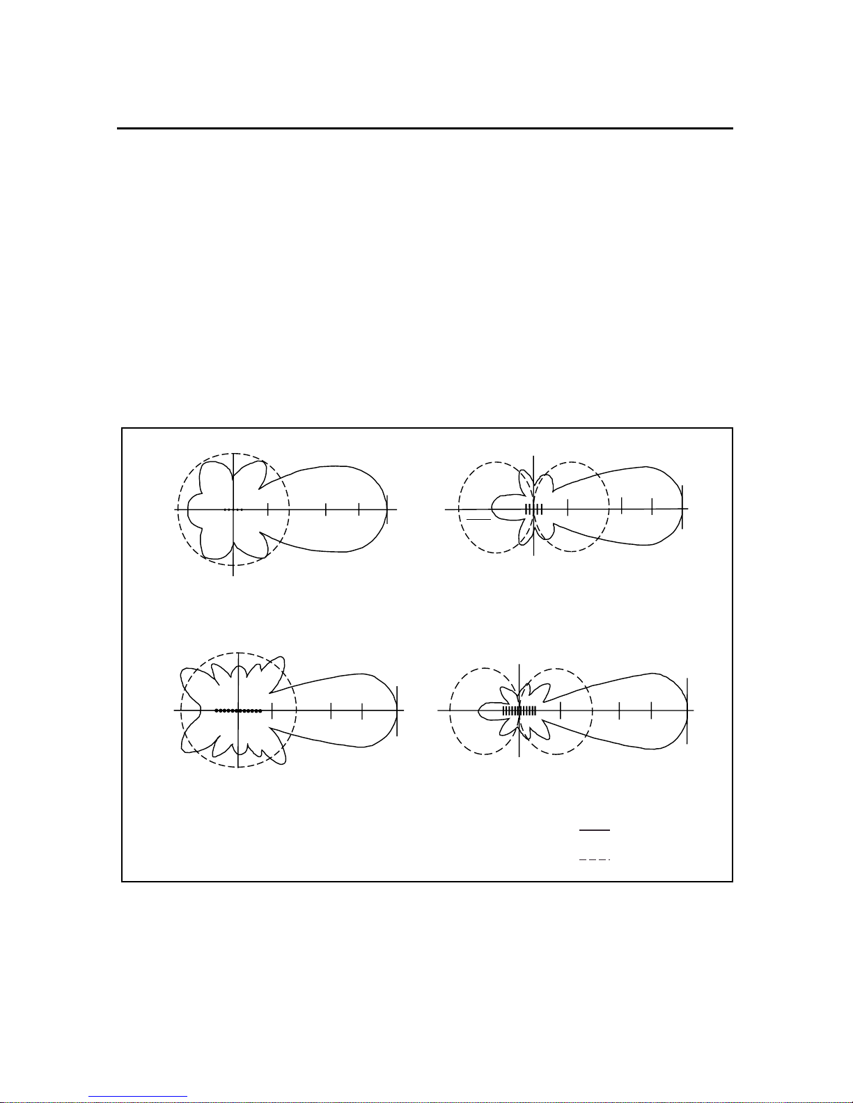
Two directional antennas, a 9 dB Yagi and a 12 dB Yagi antenna, are
available as options, dependent on applicable governmental
regulations. Figure 3-2 shows the radiated energy patterns of the
directional antennas that can be used with the radio modems. The
solid line depicts the directional antennas as compared with the
dashed lines representing the omnidirectional antennas. In principle,
the direc tional antenna is simil ar to a flash light while an
omnidirectional antenna is similar to a light bulb. The flashlight
concentrates light into a narrow beam while a light bulb illuminates
evenly, but usually not as far as the flashlight.
3
180
horizontal pattern
180
horizontal pattern
90
-11 dB +1 dB +5 dB +9 dB
270
9 dB directional antenna patterns
90
-8 dB
270
+2 dB +8 dB +12 dB
12 dB directional antenna patterns
90
180
0
vertical pattern
180
0
vertical pattern
-11 dB +1 dB +5 dB +9 dB
270
90
-8 dB +2 dB +8 dB +12 dB
270
directional
Antenna
omnidirectional
Antenna
0
0
Figure 3-2 Directional Antenna Gain Patterns
3-4 TRIMMARK 3 User Guide
Page 51

3 Characteristics and Specifications
A Yagi antenna focuses the radiated power into a directional
transmission used for straight lines (±20° for the 9 dB directional
antenna or ±17° for the 12 dB directional antenna). Since most of the
power is focused in on e direction, a Yag i antenna transmits further in
this direction than an omnidirectional antenna.
The line-of-sight range increase for a unit using the 9 dB directional
antenna is about 1.6 times that obtained using the 5 dB
omnidirectional antenna. The line-of-sight range increase for a unit
using the 12 dB di recti onal a ntenna is about t wice t hat obt ained using
the 5 dB omnidirectional antenna. The radio modem range varies
depending on line-of-sight visibility, blockage or absorption by
vegetation, ante nna pointing errors, ant enna height, terrain an omalies,
and local weather conditions.
Note – Directional antennas are useful for working in a straight line
such as along railroad tracks or roads, or where repeaters are
inconvenient or impossible such as crossing lakes, or between
mountains. Directional antennas have a limited ability to receive radio
signals from any direction other than the direction in which they are
pointed. For omnidirectional situations, the 0 dB or 5 dB UHF
omnidirectional antennas are recommended.
Because of the trade-off between gain and vertical coverage, the
TRIMMARK 3 is shipped with a 0 dB/5 dB UHF antenna tuned to
the frequency band of your radio modem.
TRIMMARK 3 User Guide 3-5
Page 52

Characteristics and Specifications
3.2 Broadcast Network
The following sections describe the frequency bands, channel
spacings and wireless data rates available with the TRIMMARK 3
radio modem.
3.2.1 Frequency Band and Channel Selection
The TRIMMARK 3 Base/Repeater radio modem operates in one the
following frequency bands:
• 410 to 420 MHz (UHF)
• 430 to 450 MHz (UHF)
• 450 to 470 MHz (UHF)
Each unit operates in one of these bands, not across bands. The
TRIMMARK 3 radio modem stores up to 20 factory pre-p rogrammed
frequencies, and operates on one of these frequencies, depending on
which is selected. All 20 frequencies must reside within one of the
above frequency bands. These frequencies are preset at the factory.
3
3-6 TRIMMARK 3 User Guide
Note – Each radio modem in a network must be tuned to the same
frequency in order for the network to operate.
In addition, the TRIMMARK 3 radio m odem is avai lable in two
different channel spacing configurations: 12.5 kHz and 25 kHz.
Channel spacing refers to the minimum separation, in Hz, between
two adjacent frequencies and can be viewed as the tuning resolution
of the radio modem. Channel spacing is dependent on local
government regulations.
Page 53

3 Characteristics and Specifications
3.2.2 Wireless Data Rate
The wireless data rate is the speed, in bits per second (bps), at which
the base unit transmits data to t he rov er unit. The TRIMMARK 3 can
be used at 4800, 9600 or 19200 bps.
3.2.3 Transmit Power
Note – Each radio modem in a wireless data network must have the
same wireless data rate and cha nne l spa cing.
The TRIMMARK 3 can be used as a base transmitter or repeater.
Each unit can be configur ed to 2, 10 or 25 Watt power output. This is
user selectable from the front panel, or configured with the
WinFLASH utility.
Note – Using the minimal power setting for your specific application
offers two benefits, lower battery consumption, and reduces the risk
of interfering with other users on your frequency.
TRIMMARK 3 User Guide 3-7
Page 54

Characteristics and Specifications
3.3 General Specifica tions
The following tables contai n information on the TRIMMARK 3 radio
modem and antennas.
Table 3-1 TRIMMARK 3 Physical Specifications
Size 12.5 cm (4.9 in.) Wide
22.9 cm (9.0 in.) Deep
7.9 cm (3.1 in.) High
Weight 1.59 kg (3.5 lbs.)
Power Input 12 to 16 VDC, nominal
Connectors Power 2-pin LEMO (+VDC, GND)
Data 7-pin female LEMO (supports
Antenna TNC female
Temperature Operating –40 ° to +65 ° C (–40° to +149° F)
3
RXD, TXD and SGND)
Storage –55° to +75° C (–67° to +167° F)
Humidity 100%, fully sealed, weatherproof
3-8 TRIMMARK 3 User Guide
Page 55

3 Characteristics and Specifications
Table 3-2 Antenna Physical Specifications
Type Length (typical) Weight
Standard 0 dB UHF
omni whip
Standard 5 dB UHF
omni whip
47 cm (18.5 in.) 0.5 kg (1.0 lb.)
99 cm (39 in.) 0.5 kg (1.1 lb.)
TRIMMARK 3 User Guide 3-9
Page 56

Characteristics and Specifications
Table 3-3 Performance Specifications (Typical)
3
Transmit Power 2W, 10W, 25W
1
Wireless Data Rate 4800, 9600 or 19200 bps
Frequency Bands 410-420 MHz, 430-450 MHz, or 450-470 MHz. Only
one band per radio modem
Channel Spacing 12.5 kHz or 25 kHz. Only one per radio modem
Number of Channels Up to 20 factory pre-programmed frequencies,
internally stored
2
RF Modulation Format Gaussian Minimum Shift Keying (GMSK)
Range Typical: 25W Base: 10 to 12 km (6-7 miles)
2W Repeater: 5-8 km (3-5 miles)
Varies with terrain and operational conditions
Up to two repeaters can be used to extend range.
Power Consumption
3
25W Base: 75 W consumption @ 4800 bps
25 W consumption @ 9600 bps
Battery Life
3
25W Base: 8 hours on one 18Ah
battery; typical at 20°C
(70°F) @ 9600 bps
2W Repeater: 16 hours on one 18 Ah
battery; typical at 20°C (70°F)
Serial Port
4
One set of RS-232 signals available. Data is 8 bits with
selectable parity and 1 stop bit. Supported data rates
are 9600, 19200 and 38400 bps.
1. All units are shipped from the factory set at 2 watts power output.
2. Use the same frequency for all radio modems in the same wireless data network.
3. Power consumption, and battery life, depends on the broadcast information content and
wireless data rat e (e.g., CMR versus RTCM SC-1 04 Ver. 2.x packets at 1 Hz epoch rates
versu 5 Hz epoch rates).
4. Communications rate between the Radio and GPS Receiver, not Wireless Rate.
3-10 TRIMMARK 3 User Guide
Page 57

4 Troubleshooting
This chapter lists st atus messages and troublesh oot ing tips which can
be used to help isolate and correct system configuration or
operational issues. Status messages may be disp la yed as a one or two
line message on the front panel of the unit. Two line messages listed
below are separated by a comma.
4.1 Status Messages
Battery Low
The battery voltage is below 11.6 volts. Replace the battery
as soon as possible.
Battery Low, Radio Turned Off
The battery voltage has dropped below 10.8 volts, and the
radio has stopped transmitting. Replace the battery, the unit
will reset and begin transmitting again.
TRIMMARK 3 User Guide 4-1
Note – Battery Low voltage levels are approximate and may vary
according to various factors; battery condition, radio modem
operating mode and other environmental factors.
Data Overload, Check GPS Config
Occurs wh en wireless data rate is set too low for the amoun t
of data you are attempting to transmit, for example, 5hz
CMR’s at 4800 baud. Increase the Wireless Data Rate or
change the type of packets you are transmitting.
Page 58

Troubleshooting
4
Comm Port Error, Check Data Rate
The communications protocol between the GPS receiver and
the radio is incompatible. With WinFLASH or the Data
Collector reconfigure the GPS and Radio Modem protocols
to the same settings.
Warning:, Radio Hot
The radio is approachi ng, but has not ex ceeded it’s maximu m
operating temperature. This may occur due to high data rate
transmission at maximum power output (25W), and/or
operating the unit in direct sunlight. Reduce power output,
data rate, shade the unit from direct sunlight.
,
0
Caution – The housing of the TRIMMARK 3 will be HOT to touch if
the Radio Hot message is displayed. Use caution and reasonable
care when handling the unit in this state.
Warning: Radio, Hot Output Off
The unit has exceed ed it’s maximum internal operating
temperature, (
transmitting. This may occur du e to high data rate
transmission at maximum power output (25W), and/or
operating the unit in direct sunlight. Allow the unit to cool
down. Reduce power output, data rate, shade the unit from
direct sunlight.
Warning – Operating or storing your TRIMMARK 3 radio modem
outside the specified temperature can damage the instrument.
Warning: No, External Battery
Indicates the unit is receiving power from the GPS receiver
through the Data port, but does not have power connected to
it’s main power port. If used as a Base, the GPS receiver
cannot supply adequate power for the radio. Connect an
external power source to the radio.
+85° C / +185° F), and has stopped
4-2 TRIMMARK 3 User Guide
Page 59

4 Troubleshooting
Connect Antenna, to Radio
The radio modem is at tempting t o transmit but does not sense
an antenna connected to the antenna port. Connect the radio
antenna to the unit. If the antenna is physically connected to
the unit, the cable and/or antenna may have failed. This
message will not appear if the unit is configured as a rover,
even if there is no antenna connected.
ERROR:, Bad Radio Config
The radio was configured incorrectly. This may occur after
upgrading the radio firmware. Reconfigure the radio modem
using WinFLASH or the Data Coll ector.
HARDWARE ERROR:, XX (code number)
This is a FATAL ERROR. The radio modem should be
returned for service. Please note the error code and contact
Trimble or your local service provider
4.2 Service
There are no user serviceable parts in the TRIMM ARK 3 Radio
Modem. Contact your Trimble representative or local service
provider for assistance.
TRIMMARK 3 User Guide 4-3
Page 60

Troubleshooting
4
4-4 TRIMMARK 3 User Guide
Page 61

A Using Radio
Communication
Systems with GPS
Surveying Receivers
Trimble Publication 1-612-0082-2/94
"GPS receiver, antenna, tripod, tribrach, tape, cones, flagging,
radio...", such is the checklist of most GPS surveyors preparing for a
day of observations. But a truly successful survey is not just a matter
of making sure that you have all of the equipment, you must also
ensure that you optimize the usage of these new tools for the highest
productivity.
The GPS re ceiver is try ing to measure very faint radio signals from
satellites orbiting at 22,000 kilometers in space. There are many
factors that can hinder the receiver’s abil it y to per fo rm . Fo r exa mple,
placing your hand over the antenna or setting up the antenna under a
tree are factors that have already proven to interfere with GPS signal
reception.
TRIMMARK 3 User Guide A-1
Page 62

Using Radio Communication Systems with GPS Sur veying Receivers
As GPS receivers developed, their processors have become more
sensitive to incoming data flow. This provides an increase in ac curacy
by extracting more information out of the GPS radio signal. But with
this gain in accuracy, there is an increased susceptibility to other radio
signals. The receiver is now more sensitive to the incoming GPS
signal, and consequently it is also more sensitive to other incoming
radio signals. This means that communications radios, such as ones
commonly used by su rveyors, c an sometimes create d iff iculty with
the GPS signal reception.
There are some very simple steps you can fo llow to remove the
effects of ra dio interference on th e GPS r ece iver . First, you should be
aware of the type of communications equipment you’re buying and
understand its characteristics. Secondly, a little care in using
communications radio can greatly decrease your chances of
experiencing any interference with satellite tracking.
A
A.1 Selecting Communications Radios
If you do not already have communications radios, and are thinking
of buying them to supplement your survey activities, there are a
number of factors to keep in mind before purchasing: (a) some
frequencies can cause interruptions or GPS tracking; (b) certain
communications equipment creates spurious signals not related to
their frequency that can interfe re with satellite trackin g; and (c)
powerful communications transmitters can create such a strong radio
signal that the GPS signal cannot be identified.
Most communication transmitters emit overtones of their assigne d
frequency. If these overtones line up with the GPS frequency, it can
filter into the GPS equipment and interfere with the satellite tracking.
Some communication transmitters emit more of these overtones than
others. But the number of overtones can be difficult to determine and
is not the most important factor when considering this nuisance
parameter. To avoid being affected by transmitter overtones, simply
avoid those frequencies that lie within the GPS frequency range.
Table A-1 shows frequency bands that you should avoid
A-2 TRIMMARK 3 User Guide
Page 63

A Using Radio Communication System s with GPS Surveying Receivers
.
Table A-1 RF Bands to Avoid When Using GPS
Surveying Receivers
From this Frequency To this Frequency
781.210 794.210
607.300 620.300
520.806 529.473
404.866 413.533
390.605 397.105
312.484 317.684
303.650 310.150
260.403 264.736
242.920 248.120
223.202 226.917
202.433 206.766
195.302 198.552
173.602 177.228
156.242 158.842
151.825 155.075
142.038 144.401
134.955 137.844
130.201 132.368
120.186 124.060
110.418 113.458
TRIMMARK 3 User Guide A-3
Page 64

Using Radio Communication Systems with GPS Sur veying Receivers
Some communication transmitters and receivers also emit spurious
signals. These are e xtremely diff icult to predict. So, th e only way to
know if your receiver is being hampered by spuriously emitted
signals is to test the communi cation equipmen t with the GPS receive r .
If you plan to buy a new radio, the best course of action is to test it
with your existing GPS equipment, to determine if any problems
exist.
Communications equipment that uses more power is more likely to
create noisy signals from which the GPS signal cannot be extracted.
This case typically occurs from signals emitted from the radio
transmitter box and not its antenna. Non-GPS signals enter the GPS
system through the GPS antenna and not through the receiver.
Therefore, most of the effects of non-GPS signals can be minimized
by physically separating your radio and GPS equipment.
A
A-4 TRIMMARK 3 User Guide
Page 65

A Using Radio Communication System s with GPS Surveying Receivers
A.2 Useful Field Procedures
There are a few useful field procedures that you can follow to
minimize the effects of your radio. Since most of the radio signal in
the GPS band is emitted directly from the radio transmitter box and
received via the GPS antenna, make sure the GPS antenna is
separated from the radio transmitter by 2-3 meters (7-10 feet). If you
are still experiencing difficulties at this distance the GPS signal may
be getting over-powered by the radio transmissions. In this case, you
can either separate the equipment even more or shield the radio
transmitter .
Radio signal strength drops as you move further away from the
source of the transmission – dropping as a square of the distance.
Therefore, if there is a problem, separate the GPS antenna and radio
even more to lessen the strength of the radio signal received at the
GPS antenna.
If you are using a geodetic ant enna, you ca n use the ante nna’s ground
plane to shield the radio waves. In fact, you can shield the antenna
from the radio signal by moving behind nearby objects such as a car
or tree. If you cannot move away from the GPS antenna, move the
radio below the level of the GPS antenna ground plane. This is not
ideal, but may help in those cases where you are left with no
alternative.
TRIMMARK 3 User Guide A-5
Page 66

Using Radio Communication Systems with GPS Sur veying Receivers
A.3 Summary
Using communications radios with GPS receivers requires some
special considerations. By striving to extract the utmost accuracy
from the GPS system, receiver designs have made greater use of the
radio spectrum. However, the methods used to increase performance
and accuracy also make GPS receivers more susceptible to receiving
other radio signals.
Radio signals in the GPS band arise from a few different sources.
Some radio transmitters produce overtones of their frequency, which
lie within the GPS P-code frequency range. Others create random,
spurious signals, which affect GPS signal reception. Still other radio
systems use high power levels to boost communication range and
create noise that limits the GPS signal tracking. These are all
characteristics to avoid when purchasing or using communications
equipment in conjunction with GPS.
Before using radios on f ull-fl edged survey job, it is a good idea t o test
the communications equipment to determine if it affects the GPS
signal recepti on in any way . Testing radios with the GPS equip ment is
especially import ant if you are conside ring purchasing new r adios. Be
sure to always:
A
• Choose the communication frequency of your radios
carefully so they do not transmit on or create harmonics in
the frequency range of GPS.
• Prior to buying radi os, make sure th at you test th em with your
GPS receivers.
• If problems arise, put some distance between the radio
transmitter case and the GPS antenna. Also, shielding the
radio transmitter should minimize the effects of radio signals
on the GPS signal reception.
Radio signal strength drops as a function of distance. The greater the
separation betwee n the GPS ant enna and the radio trans mitter , the l ess
likely you are to experience the interruptions in satellite tracking.
A-6 TRIMMARK 3 User Guide
Page 67

Index
Numerics
1 stop bit 2-1
38400 bps 2-1
8 data bits 2-1
A
antenna 2-13
0 dB 3-2
5 dB 3-2
doubling broadcast power 1-7
doubling height 1-7
installation 2-13
obstructions 2-13
omnidirectional 3-1
ANTENNA connector
TRIMMARK II Base/Repeater 1-
9
antenna gain 3-1
Antenna Physical Specifications 3-17
audience xv
baud rate
serial port 2-2
C
cautions xx
characteristics 3-1
COM port 2-2
CommSet 2-3
CommSet Utility 2-2
CommSet utility 1-13
configuration
TRIMMARK II Base/Repeater 2-
1
TRIMMARK Ro ver 2-1
Configuring the Serial I/O Port 2-2
Connecting to a PC 2-2
connector
POWER & I/O 3-8
controls 1-10
copyright ii
B
battery selection 3-10
TRIMMARK II Base/Repeater 3-
10
TRIMMARK 3 User Guide Index-1
D
DATA connector
TRIMMARK II Base/Repeater 1-
9
data modem 2-1
Page 68

Index
defaults
TRIMMARK II Base/Repeater 1-
13
Directional Antennas 1-15
directional antennas 2-18
disclaimer of warranty iv
document conventions xix
E
electrical interface 3-8
equipment sets
TRIMMARK II Series Bas e 1-3
TRIMMARK II Series
Repeater 1-4
Equipment Sets and Accessories 1-3
F
I
I/O cables 1-13
indicators 1-10
installation 2-8
antenna 2-13
L
licensing 5-2
limitation of liability iv
limited warranty
firmware iv
software iv
line-of-sight
LOS 1-1
line-of-sight (LOS) 1-7
LOS 1-1
LOS (line-of-sight) 1-7
features
TRIMMARK II Base/Repeater 1-
2
File Transfer Protocol (FTP) site xvii
format
serial I/O port 2-2
frequency bands 1-7
Frequency Updates 2-7
front panel
TRIMMARK II Base/Repeater 1-
8
ftp.trimble.com xvii
G
general care 4-4
General Specifications 3-16
Index-2 TRIMMARK 3 User Guide
N
notes xx
notices iii
O
odd parity 2-1
operation
TRIMMARK II Base/Repeater 2-
1
TRIMMARK Ro ver 2-1
organization xv
overview 1-1
Page 69

Index
P
Performance Specifications (Typical) 3-
18
Permanent Base Omnidirectional
Antennas 1-14
physical specifications
TRIMMARK II Base/Receiver 3-
16
power and I/O cables
TRIMMARK II Base/Repeater 1-
13
POWER I/O connector
TRIMMARK II Base/Repeater 1-
9
preface xv
R
radio 2-1, B-1
Radio Frequency Bands to Avoid When
Using GPS Surveying Receivers B-3
reader comment form xix
rear panel
TRIMMARK II Base/Repeater 1-
9
regulations 5-1
repeater 1-1
revision notice iii
RF energy iii, 5-3
rover 1-1
S
safety 5-1
scope xv
Selecting Communicati ons Radios B-2
Serial I/O Port
configuring 2-2
serial I/O port
format 2-2
serial port
baud rate 2-2
service 4-4
setup 2-3
specifications 3-1
Standard Omnidirectional Antennas 1-
14
T
TAC xviii
technical assistance xviii
Technical Assistance Center
TAC xviii
tips xx
trademarks iii
Trimble Publication 1-612-0082-2/
94 B-1
TRIMMARK II Base/Receiver
battery selection 3-10
physical specifications 3-16
TRIMMARK II Base/Repeater
configuration 2-1
connector
ANTENNA 1-9
DATA 1-9
POWER I/O 1-9
DATA connector 1-13
front panel 1-8
POWER connector 1-13
rear panel 1-9
TRIMMARK II Series Ba se equipment
set 1-3
TRIMMARK 3 User Guide Index-3
Page 70

Index
TRIMMARK II Series Radio Modem
network 3-1
TRIMMARK II Series Repeater
equipment set 1-4
TRIMMARK Rover
configuration 2-1
Troubleshooting 4-1
troubleshooting
base 4-1
repeater 4-3
Type Approval 5-2
Typical Broadcast Network 1-7
U
update notes xvi
Useful Field Procedures B-5
Using Radio Communication Systems
with GPS Surveying Receivers B-1
www.trimble.com/support/
support.htm xvii
V
verifying base operation 2-19
verifying operation
TRIMMARK II Base/Repeater 2-
19
verifying repeater operation 2-20
W
warnings xx
wireless data link 2-4
wireless data links 1-7
Wireless Data Rate 3-7
World Wide Web (WWW) site xvii
www.trimble.com xvii
Index-4 TRIMMARK 3 User Guide
 Loading...